Week 3:- BiW Fixture Design Methodologies Challenges
BIW FIXTURE DESIGN MATHODOLY
1) WHAT IS DESIGN MATHODOLOGY?
Answer:-DESIGN METHODOLOGY:-Design methodology is nothing but the steps followed during the concept designing stage of fixture design. below are the step followed during design methodology.
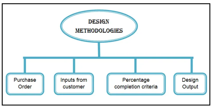
A)Purchase order:- Purchase order is bsically confirmation from customer side that we are ready to start work. A purchase order (PO) is a commercial document and first official issued by a buyer to a seller indicating type, quantities, and agreed prices for product or services. It is used to control the purchasing of product and service from external suppliers. purchase order can be an essential part of enterprises resource.
B)Planning system order:- Indent is purchase condition sale. The issue of a purchase order does not itself form a contact. If no perior contact between the buyer and seller .
C)Input form customer:-Input from custumer are major input that we get from customer. We study those input to what kind of information get out it .
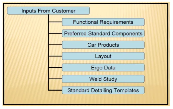
Designer needs following basic information to start the BIW fixture .
- First understand scope of the work. mean what is expcted by cutomer every customer has its specific requirement and it may own raw material , electric, pneumatic, cad design standards. Every customer also gives different input and expects output e.g 2d drawing. Process sheet in xls, pdf, CAD format of design, layout format, OLP.
- Bill of Material (BOM) of the component to be welded-spot welding
- CAD panel data or at least 2D drawing of assembly and individual panel data.
- Sheet metal panel thickness plays major role to decides 2 metal or 3 metal weld .
- Spot Detail information like total no. of spot and spacing between the spots
- Weld information clarity from from drawing like 2 metal 3 metal welding .
- PLP(Principle loaction scheme) of the individual panel and total robotic welding sequence, no of clamp data and data is mentioned.
- All clamping cylinder and fixture.
- CAD - software guidlines
- Raw matrial standareds
- Dseign guidlines
- Bought out item(Purchased parts) standards like pneumatic items, toggle clamp, bearing screw, dowel etc company infromation.
D)Design output
- Output consist 3D model , 2D drawing which is detailing parts , BOM & other related documents.
- It is followed in designing stages & dispatch stages of the welding fixture.
- It ensure that how much task that we have decided to complete with in the stipulated time is complete or not & how much of it is rest to complete & whether it going to be complete or not in given time.
- There are some tools which are multiple units on common based are called inuitized tools which includes no. the same base .
- They are some tools are multiple units on common base called unitized tools for ex. fixture which include no of unit on the some base .
- The require two type of drawing sheet as follows as follows .
- 1. key sheet -it is the detailed drawing individual all their components
- Non unitized tools which can be completely detailed in layout sheet.
2) WHAT ARE THE INPUTS REQUIRED FROM THE CUSTOMER TO START DESIGNING OF FIXTURE?
Answer:-
The inputs required from the customer to start designing a fixture :
1.Funtional requirements.
2.Preferred standard components
3.Car products loyout
4.Layout.
5.Ergo -data .
6.Weld study.
7. Standard detailing templates.
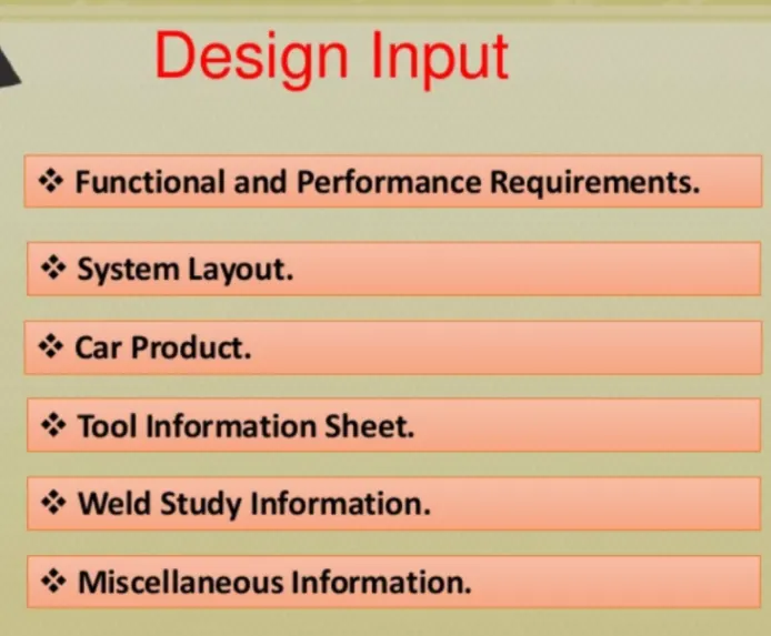
1.Functional Requirements:
The purpose or the function of the fixture will be given from the customers like what are the process the fixture is joining to do i:e welding (spot or seam weld).
gluing ,receting, hemming or whether it us checking fxture or storage rocks etc it is one of the basic requirement to get from the customer to start designing a fixture.
2.Preferred standards:
As we know different companies follow different standards, we will be following the standard customer by following standards the time of designing and manufacturing of parts will be saved which will be automatically minimizing the time of the projects.
As for the standards parts. it can be easily replaced from the used fixture to the new fixture which reduce the cost
some of the preferred standard components used in BIW fixtures are given below,
1.Standard like ABB,NAAMS,DESTACO,ZYTRAN,TUNKERS are used in design& manufacturing of fixtures.
2.Standard parts like Risers,L-blocks,retainers,pins,NC blocks,Shims ,etc.
3.Components like clamps,cylinders,slides,switches,sensors,etc.
4.Weld guns,Tip dressers,Tool changers,etc.tip dressers are to sharpen the tip of the tools whereas tool changes are used in robots to do various process.As robots are too costly,tool changers are used.
ABB-It is a Robots manufacturing company.
Some example of description of standard robots are Robust IRB7600 robots,which can,hold the panels securely and accurately in place while IRB 6640robots perform the welding.
The below picture shows the welding line is installed at great wall motors (GWM) recently opened and internationally acclaimed automatibve plant in Tianjin,China.One of the factory's most highly publicized and productive manufacturing line is the ABB welding line, which comprises among the other things a fleet of ABB robots and patented ABB framing and hemming technologies.
3.Car Products:
The inputs we get from car products are GD&T, Parts list,Cadd files of car part,Clamp plan,Product assembly,Process sheet.
1.GD&T:It provides information of locating pins,rest,clamp,damp & slide unit infromation of each situation.Also includes the infromation of sequence of openings of clamps,dumps & slide stroke information.
2.Parts lists: It gives the lists of parts which are going to assembled in the fixture.The list contains the information of part number,part name,revision of fixture,part thicknes,etc.
3.Clamp plan: Clamp plan provides the information of location of pins,Rest units,clamp unit,dump etc.It is the important input from customer.The clamp Plan/position should not be changed without the knowledge of customer.
4.3D cad file:The 3D model of the car part will be given from customer.From that 3D model we will be developing our fixture design process.The 3D cadd file will be in the format of step file(stp) or IGES file (igs).
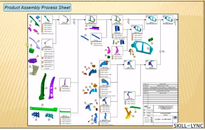
5.Product assembly process sheet:It gives the information of stage wise assembly process like how the parts move from one assembly process like how the parts move from one assmbly station to other after completion of joining process.
4.Layouts:
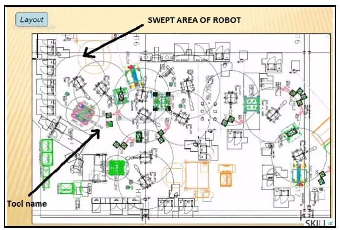
Layout shows the entire assembly plan to understand the process.
Layout provides the information of flow of parts,station pitch,robot stations,accessories like tool changers & tip dressers, sub assembly links,plan from height,loading/unloading sequence/height.
5.Ergo Data:
As same as preferred standards, differnt companies follow different standards of ergo data.We have to follow the customer sandards of ergo data.
The inputs of ergo data will given by the customer mostly in case of manually operated fixtures/manual fixtures.
The ergo data is mainly used to make the operator comfortable which may leads to improve the efficiency in cycle time & production.
Ergo data provides inputs like platform height,maximum & minimum reach from operator to fixture,maximum & minimum height of the fixture ,whether the child parts/assemblies are visible while clamping or loading & unloading.
Also provides informations like loading height,working safety zone of operator,etc.
6.Weld study:
Weld study is the impotant inputs given by the customer. It gives details about the study of particuler gun that we use for welding.
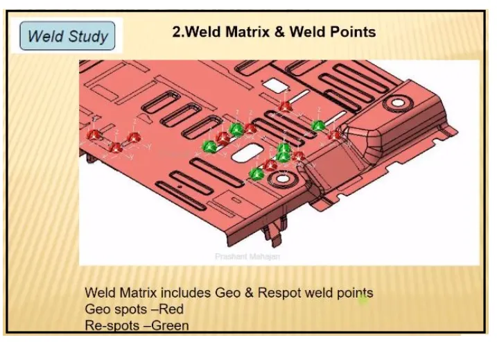
Also the datails like No. of weld, position of weld in the components will be given. In short,weld study includes weld gun details,weld matrix & weld points. Generally weld points will be given in sphers.
7.Standard detailing templates:
This inputs includes the detailing of 2D cad drawing as per the customer standards.So we have to follow the detailing templates as per the customer standards.
3) WHAT IS THE INPUT WE GET FROM"CAR PRODUCTS"?
Annwer:-Following input we get from car product.
a).GD&T -Geometric dimensioning & Tolerance of the part for which the fixture have to be designed.GD&T provides information about locating pins,Rest,Clamp,Dumps & Slides information of each station & Sequence & Opening of clamps,Dumps & Slide stroke infromation.
b).Part list:Part list is nothing but listing down all the parts of assembly.It includes information about the part name,Part number,Tooling revision,Part thickness etc.Suppose first assembly has gone between hoos inner panels & latch which going to attach next hinge going to attach.So there are different list of assembly we are going to perform.So everyday aseembly will have different fixture unit.
c).CAD file: 3D file of that car product require from customer.The 3D model file of the car part is given from customer to study on it.The car part is designed by using 3D modeling software.From this we can get some conceptual idea of the designing of fixture.The model is going to be the base of the fixture design.Below figure illustate.
d).Clamp plan: It provides information about position of clamp unit,pin unit,rest unit,dump unit etc.This major input from customer & it should be never be changed without permission of customer.Clamp plan provide exact location of pins,rest,clamp etc.It is in more detail.It gives exact location in X,Y & Z co-ordinates value to start designing.
e).Product assembly process sheet: Product assembly process sheet is sheet that gives following detail.
- Part assembly sequence
- Sequence of operation
- Cycle time.
It gives detail process of the completion of the part from scratch to the finished product assembly.It will give detailed paln of component how they welded as well how product is moving from one assembly to other? this process plan should not be changed without permission of customer .Below figure shows.
4.what is clamp?
Answer:-A clamp is a force - actuating mechanism of a fixture . The force exerted by the clamp holds a part securely in the fixture against all other extrnal forces. clamping surface are subjected to the clamping force for obtaining invariant location . To fix a parts at a paticular position, we use 3-2-1 principle in all type of fixture to restrict degree of freedom.
Each panel is fixed keeping 3-2-1 principle in mind . This principle required us to use minimum 3 rest, 2 and 1 clamp to fix a panel. While we receive the panel, the customer also use the coordinates of panel where we receive the panel, the customer also gives us the coordinates of panel where he wants use to rest, clamp and loacte the panel. We can directly input these coordinates and designing rates clamp and pin. clamp plan document serves this purpose.
Clamp Plan provide location of pin , rest , clmap , dump etc . it is in more detail.
clamp plan is a document that contains the panel drawing mentioning all the places
where clamp and rests are to be given . it gives location in X,Y,Z co-ordinate value to start desiging . we should never changes clamp without permission of cutomer.
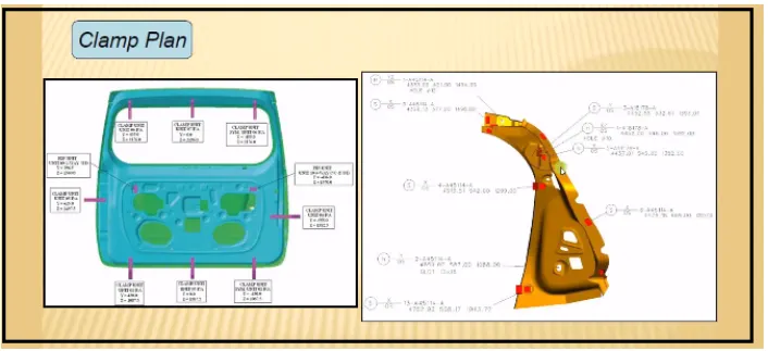
Below fig shows clamp plan.
5) What is the purpose of a layout ?
Answer:-
Plant layout is plan of an optimum arrangement of facilities including personel operating equipment, storage space material handling equipment and all other supporting service along with the design of best structure to contain all these facilities . An overall objective of plant layout is to design a physical arrangement that meets the required output quality & quantity most economically.
It shows all the objects of manufacturing line like robots, fixtures, racks etc & also shows the reach ability of the robot to the fixture also called the swept area of the robot (indicated by circle around robot). It also shows the contrains of space or the space available fpr the fixture that we are designing .
Layout provide information about flow of parts , station pitch, robot station, accessories like tool changer & tip dresser, sub assembly links, platform height, loading & unloading sequence.
6) WHAT IS ERGO DATA?
Answer:-Productivity is pawerful tool to improve the standards of living of people & to enhance the quality of work life (QWL).
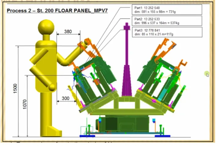
Ergonomics is concerned with man & his working conditions Ergonomics aims at providing comfort & improved working conditions so as to channelize energy, skills of workers fatigue. Ergo data is given when manual operator involved to do operation, so this input is given regards how their stands of ergo data. Ergo data provides information of loading height, wotking safety, zone of operator etc.
The final assembly of an automobile involves tasks of complex nature. These processer are on the least priority for automation. Manual labour is best suited for assembly operation with the aid minimal level of automation. All the processes have to be improved continously in order to reduce the cost and increase productivity.
The workers attain various postures: Exert froce and works continuously in cycle time to accomplish the assembly task. working along automobile lines is characterized by repetitiveness.
Ergo data is studied to identify ergonomics working postures that contributed to the serious development of muscle skeltal injuries and thus investigated possible contributory their related causes. below fig. show
ergonomically correct seating person while working .
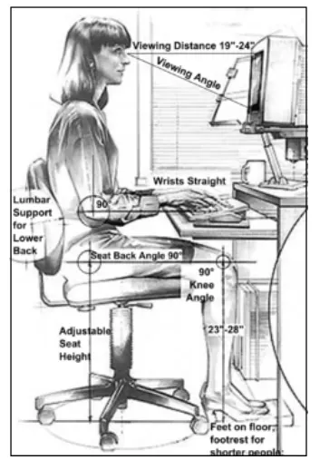
Below fig show ergo data provided by customer.
7) What do you understand by weld study?
Answer:- It include information of weld gun detail,weld matrix & weld points.There are two types of weld points geo weld point & respot weld point.Geo weld points defines the geometry of part & respot do all other remaining weld points also add strength to geo weld points.Weld study consists of spots in case of spot welding fixture that gives us the position of spot in the form of coordinates.It is most important input that we get from customer.These are the points where the panel is welded.The spots can be geo spots or respots shown in figure.
The front door inner panel and side bracket of GM sedan car are to be spot welded as shown in Fig 1.The previously spot welded inner panel assembly is then welded with the cross bracket as shown in Fig 2.The work cell and modular fixture designed must be compatible for both the assemblies to be spot welded.
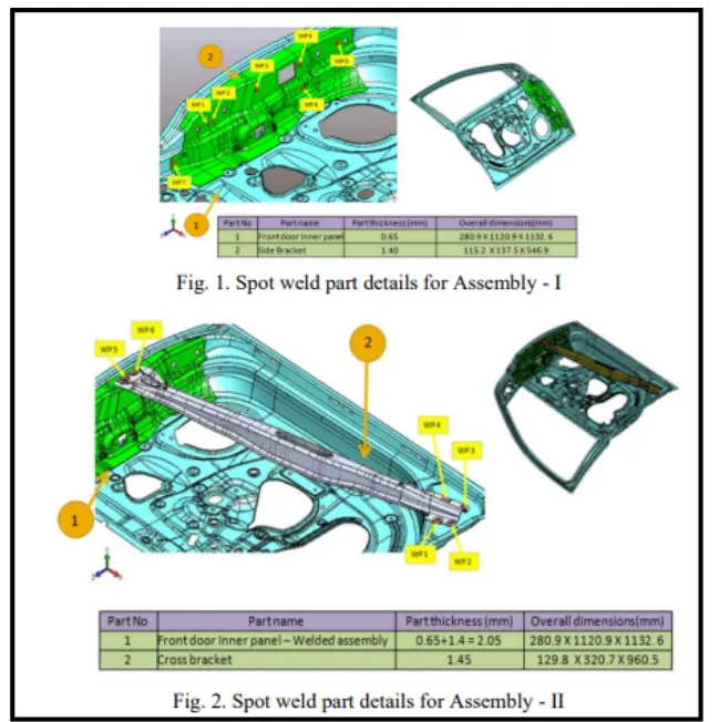
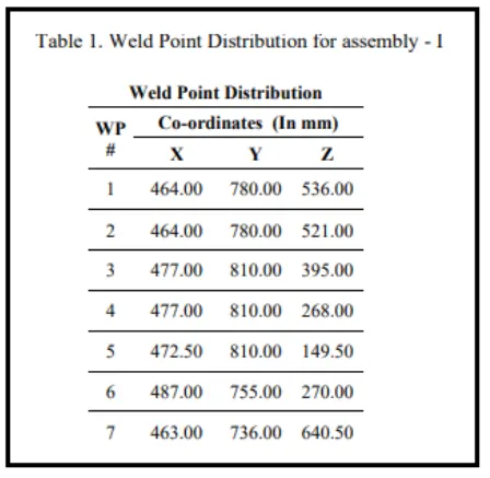
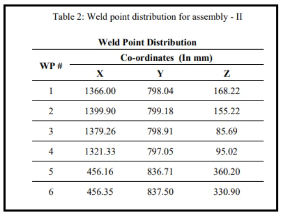
Weld spots for each weld assembly are highlighted in Figure 1 and 2 as WP1,WP2,WP3 and so on.Weld points are the locations on which spot welding will be carried out on the automobile sheet metal components.The Weld points forms the base for fixture design, the clamping plan & locating plan are done based on the weld spot distribution.The weld spots for Front door inner panel - side bracket assembly are located as shown in Table 1 with respect to the body line of car.
The weld spot locations with respect to the body line of car are as shown in Table 2.
8) What are the criteria for percentage completion in the designing stage? Explain it in detail.
Answer:-
- Percentage completion criteria are followed in the designing stage & dispatch stage of welding fixture.The percentage completion criteria contain the current status of a task, expressed as the percentage of the task's duration that has been completed.You can enter percent complete, or you can have project calculate if for you based on actual duration.
- It is followed in designing stages & dispatch stages of the welding fixture.
- It ensures that how much task that we have decided to complete within the stipulated time is completed or not & how much of it is rest to complete & whether it is going to be complete or not in given time.
0-25%-input & concept design:
This is initial stage of project input data provide by cutomer like functional requirement , customer standard etc . after studying those input the concept not fixture design is created. After completion of this task about 25% of work completed.
25-40%-complete approval & simulation check:
As concept of fixture design is created & simulation checked it is sending for customer approval. customer will study all simulation and gives his approval. if there are any change required then it has to do accordingly & again submit for approval this concept design approval from the customer after study of simulation cotributes only 15% of total design work. but with completion of this task 25-40% works completed.
Design freezing & detailing -40 to 85%:-
This phase involve design freezing after approval of concept design. freezing means finalizing concept design. Then next step is detailing as per customer standard template. with complete of this stage, almost 85% of work is completed in designing stage.
Check & final dispatch-85 to 100%:
After detailing the quality checking team start inspection of all the data & it will dispatch to the customer if it is ok as per customer standard. if there is in error in drafting it will creat issue or mistake in the manufacturing stage
9) Brief about "output" in design?
Answer:-
- It include data to be given to customer after completion of design stage. the output is 3D model & 2D drawing of the tool.
- In the fixture element design output contains detailed design of locators, detailed design of clamp detailed design of supports, positions of loactors detailed design of clamp, position of support if any type of loactor, type of clamp type of support, clamp force & supports.
- There are two type of tools in fixture design unitized tools & non unitized tool. In unitized tool there are mulitiple units on common base for e.g. geo fixture respot fixture. checking fixture, hemming station etc.
unitized tools require two types of sheet key sheet & layout sheet. Non-unitized tools that can stand alone & can be detailed completely on a layout sheet is showing orthogonal or isometric view of that entire component.
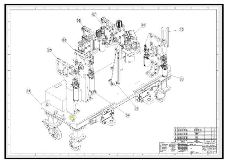
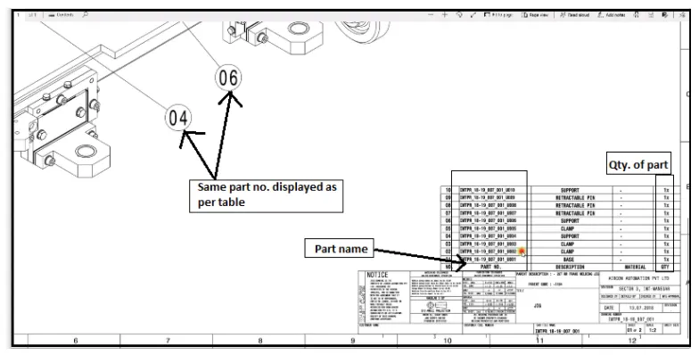
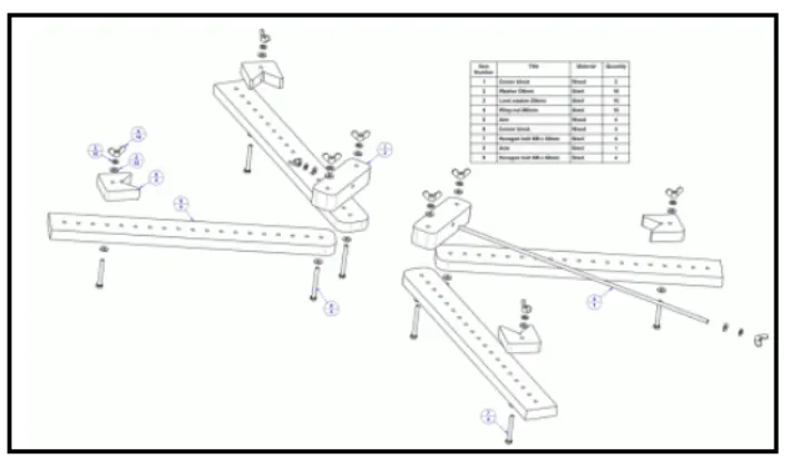
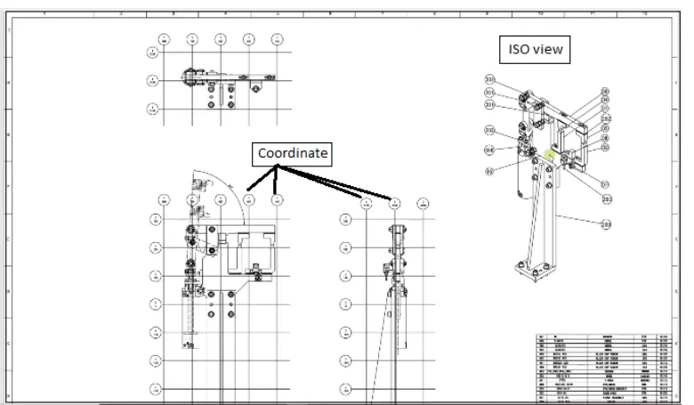
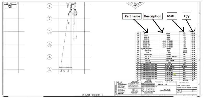
Layout sheet:A detailed drawing of individuals units to include all of their unit. layout sheet is detail drawing of that particular tool where tool where we are going details of component. grid view in below figure tells that where exactly component is located in geomerty. this is also helpful in CMM inspection of fixture.
The output should compile following point :-
a)Approved standard parts should be used wherever possible .
This saves lots of time, effort & economical.
b)Design should be as simple & economical posible. geometry is complex then fixture desgnis complex but approach is trying to design as simple as possible.
c)Deisgn must comply with all cuurent safety & ergonomics standard.
d)Design must provide for controlled damage free handling of product. it should not damage other part.
e) Adequate error proofing provision must be incorporated in each design by providing proximity switches rough loactor etc . proximity switches are basically sensor which tells part is present or not in fixture. Rough locator work as pokayoke to guid to enitre panel orientation .
f)The weight of moving part must be kept to minimum while maintaining maximum strength. weight of moving component kept as minimum as possible but it shouldn't compromise on styrength. There is balance between these two things.
g)Frames & structure are to be simply & study.
h)Desing clearance & accessiblity for routine mainenance & service.fixture need to maintain after certain period of time so it is easily accessible for maintenance.
i)Motion control must be cosidered on any moving component . adequate to control the motion of component like slider . clamp arm so that it does not give any vibration & stay certain period of time so it is easily accessible for maintenance
j) Design is reposible to be validate all clamp & weld guns. so that all clams & gun should perform its function without fail.
10) What do you understand by structure a design tree?How does it reduce error during the design process?
Answer:-Structure a design tree implies process where all the assemblies & parts are named in specific manner. different custumer have different set standard template based on that design tree structured, which helps us to identify parts Assembly, it specifies the project number, station number, unit number, parts number of each component so that it is easy to identify the parts.
It is an important process which helps us to identify a specific part or assembly ispection etc.
This helps us to avoid error during study, manufacturing, assembly, inspection etc.
If parts or assemblies are not named properly or the design tree is not structured properly, it will create confusion & create major possibilities of making an error.
Naming of a fixture, a unit or a part gives the in formation as to which project or zone or assembly they do belong.
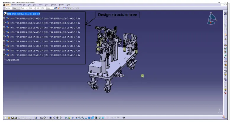
It can help us to identify quantity of items of same type or different type that are being used in assembly for e.g. bolt it actually tells you how many bolt are particular requred in that assembly or that assembly or unit. Below figure shows design tree strucure properly & component show in key sheet. Each unit has a sepsrste name .
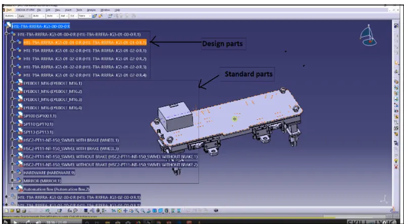
Structure the tree is important as it is easier to differentiate the manufacturing parts from standards. brought outs and hardwares. Order of tree from top to bottom is : designed or manufacutring parts, after those standards parts from customer, brought outs are at bottom in below figure, every design tree base unit is first unit.
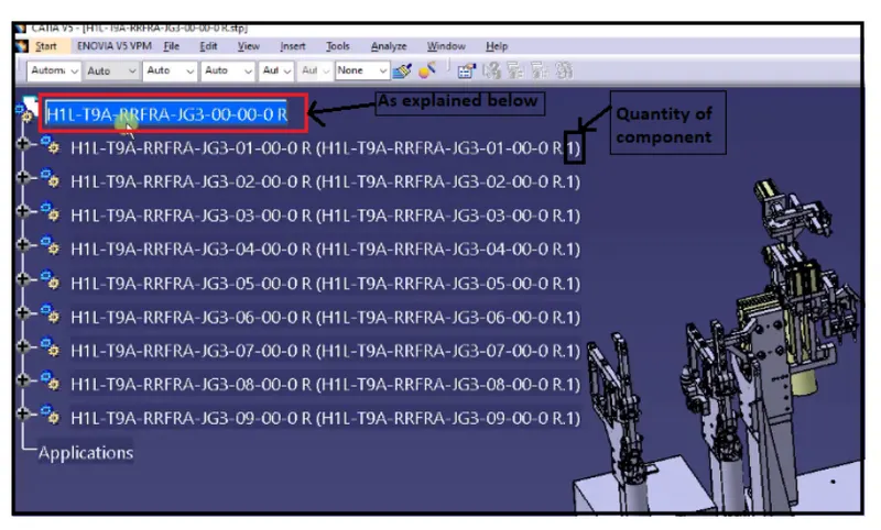
As shown in above naming is done as
H1L- T9A: Project name
RRFRA:Panel name rear panel
JG3:jig no.3
OO-OO: Unit no . part no respectively.
OR :Right side panel.
11) what are units ?Mention 5 types units.
Answer:- Welding line fixture support:-Clamp 7 locate two or more panel of a car body in welding process so that they will get welded accurately at the desired position.
A fixture may comprise a single or more unit where the product will be placed for holding or clamping or locating in order to perform operation like welding or clinching.
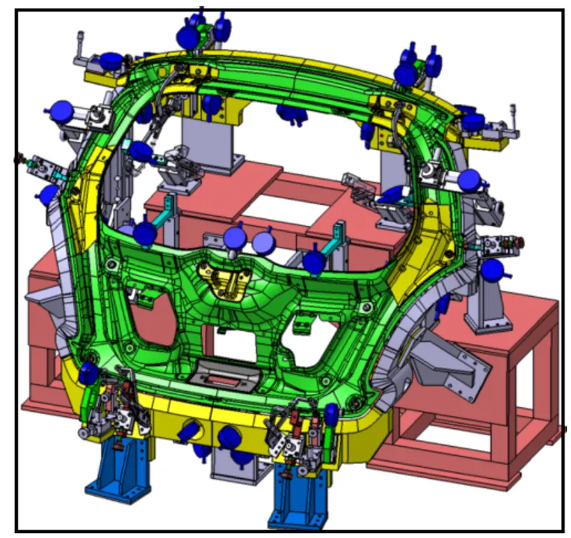
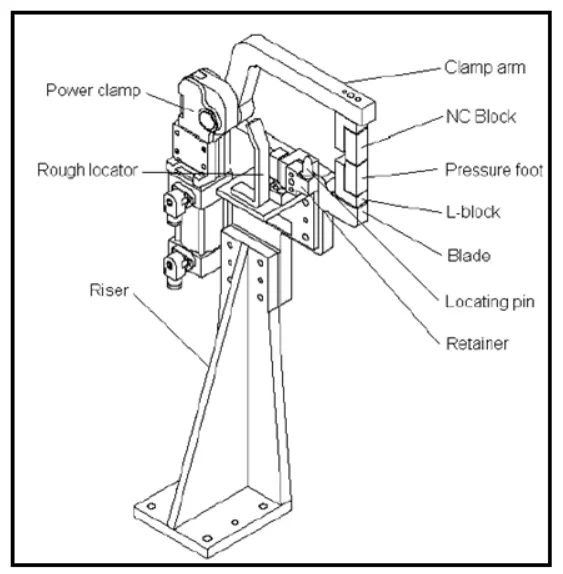
A unit which may has NC block (Mylor) locating pin , shims set, blade (Dolly plate), Power clamp, air cylinder, riser, rough locator, welding gun, fram etc. to hold or clamp or locator or weld the product at the specified location. according to the 3-2-1 principle of fixture design the unit are designed to locate & clamp the car panel to its specified position in fixture while operation is going on.
Ex . Clamping unit, Locator unit, Rest unit, Base frame unit.
A)Typical unit is shown below
Unit are categorized as below.
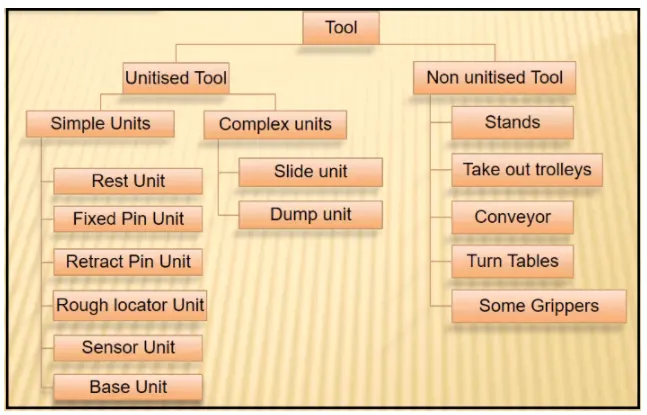
Unitized tool:-Unitized tools are bassically tools which is part of multiple unit or multiple parts inside it these are represented by key sheet . unitized tools have two types as simple unit & complex unit. Simple unit has simple design & approach for manufacturing is also simple, whereas complex unit has complex design.
Non unitized tools:- Non unitized tools are basically one unit. It doesn't have any process functionality in it. It have function to keep component stable. Example of non unitized tools are stands,takeout trolleys,conveyor,turnables etc.where we don't need key sheet for that only layout sheet is enough to tell orientation as well as position.
Below shortly described unitized tool types.
- Rest unit-Rest unit is unit designed to support car panel using Mylar/NC block/rest. Component is rested only,no upper clamp or force applied there.
- Fixed pin unit-It is unit designed to loacte car panel using pins. It is unit pin is already fixed it cannot moved.
- Retractable pin unit-It is opposite of fixed pin unit which can be moved up & down. It can be retracted to certain distance. A retractable pin unit is designed to loacate the car panel using pins,but the entire pin package parts will mounted on the retractable pneumatic cylinder.Each pneumatic cylinder will receive air through valve. When air is giiven to cylinder it is extended in forward motion & if air is given out it is retaracted. Now day's pneumatic cyliner come with locking mechanism in forward motion. Below are parts in general.
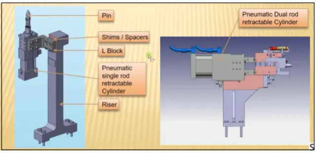
- Clamp unit:- Clamp unit is unit designed to clamp /hold the car panel with NC blocks/mylar/rest by using a pneumatic clamp cylinder & below are different parts of clamp unit in general.Usually clamp open position is 90 degrees. Fingers are attached to clamp mylar. In clmap unit shim to one side is more enough because it will restrict translation motion in upwars & downward direction only. There is another type of clamp unit known as swivel type.There is pivot pin around which calmp arm rotate.
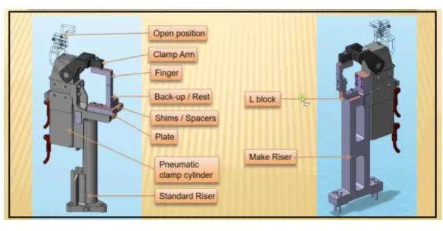
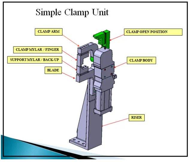
- Rough locator unit-It rougly guides the operator for locating the part.
- Sensor unit-It is designed to sense car panel using electrical sensor.
- Base unit- It is the unit on which all other units are mounted.It supports all other units.
12) Describe fixed pin units & their purpose?
Answer:-
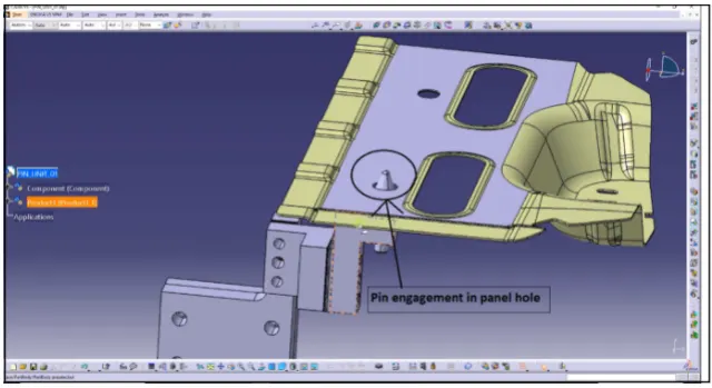
Fixed pin unit:-It is unit designed to locate car panel using pins. It is unit pin is already fixed it cannot moved & below are different parts of unit in general.Fixed pin unit basically have pin,pin retainer, shims/spacers,block,blade or adaptor plate.Pin retainer support that pin.
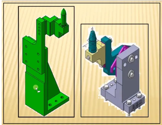
Every pin unit will have two directional shims.The block is used to mount entire pin unit. Shims ar used to avoid stack up tolerance while assembling entire component. Shims are come in pack of 0.1,0.2 & 0.5mm.
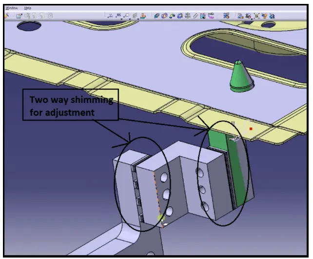
Purpose of fixed pin unit:- Pin is most important part of fixture & used to restrict rotational as well as translational degrees of freedom of that particular component.Purpose of fixed pin unit is to fix the panel translation motion along two axes to prevent rotation of panel in the axis of panel.
It supposes to have exact coordinate for it to get fix.Suppose it will move by 0.1 to 0.2mm from its original positional then entire assembly will not happen or get rejected.
13) What are the different parts of a fixed unit?
Answer:-Fixed pin unit consist of riser,blade,block,shims or spacer,pin retainer & pin. All parts are described below.
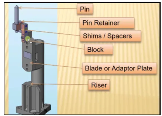
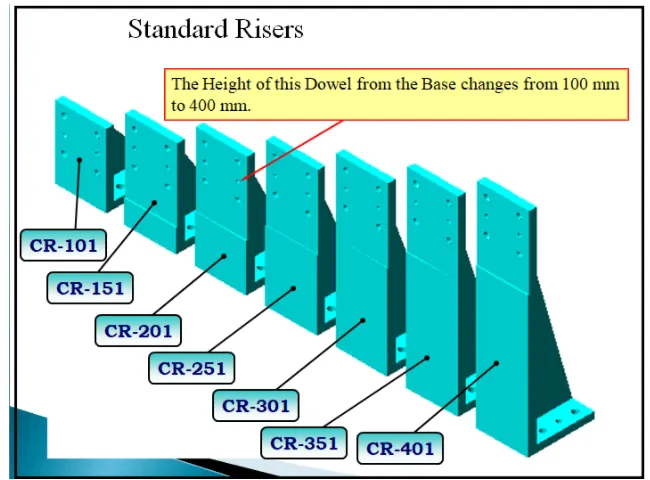
a) Riser: Risers can be of L-type,welded or square tube or frame type. These are basically manufactured parts are used to give height to assembly.
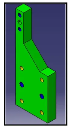
b)Blade: Blades are plates attached to riser.Other parts like cylinder,arms etc are mounted on the blade. Chamfer is given here to strengthen the blade. Two Dowel Four Hole arrangement is used to butt blade to the riser.
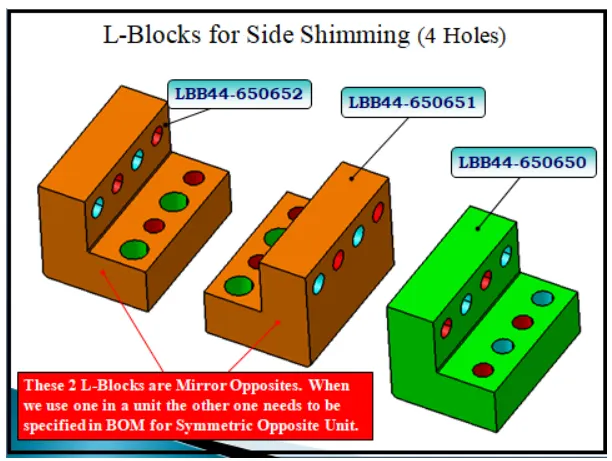
c)L-Blocks: L-Block is used just to provide the necessary shimming for adjustemnt. In case of mounting an L block,we should check bolting access as there is already a nolt to tight the pin. Hence,clear hole should be gievn from L Block
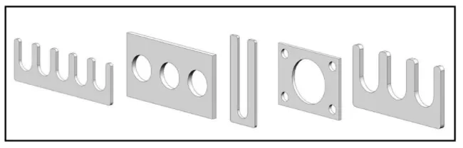
d)Shims/Spacer: In fixture ,we are providing tolerance to each part mostly manufactured. Those tolerances tend to stack up & reflect together. In order to avoid that we use shoims so we can easily adjust after assembly so whatever stack up there we will rectify it through shims. Shims come in thickness of 0.1,0.2,0.5 etc.
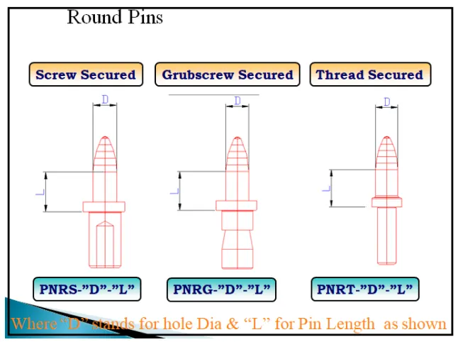
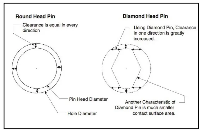
e)Pin: It is used for the location purpose of the panel. Standard pins should be used as far as possible and the lengths of pins should be reduced to maximum possible.Generally, pin diameter should be cylindrical frinded to maintain its dimension accurate. Usually two locating pins are enough to properly locate the work piece on one plane. These are dozens of styles of loacting pins that can be utilized in a design. We will explain the structure and show an example of how each style can be appled. The different types of Standard Pins are as follows:
Round Pins: These can be Screw secured (PNRS) or Grub Screw Secured (PNRG) or Thread Secured (PNRT) for Prototype build only. One of the most common pins is a stepped pin with either small or large head.
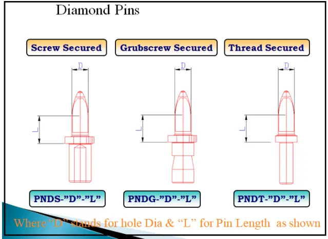
Diamond Pins: The Diamond Shape is a critical feature that helps with machining inaccuracies and smoother locating operation. When two round head pins are installed onto one plate,the distance between two mounting holes must be extremely precise and even then, the work piece will not be placed on the base as easily as it would with the use of a diamond shape pin. These can be screw secured (PNDS) or Grub Screw secured (PNDG) or Thread secured (PNRT) for Prototype build only.
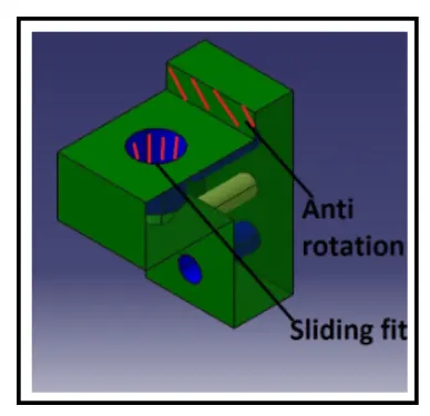
f) Pin retainer: Pin retainer support that pin. Pin retainer is designed to hold the pin in its place and is also used as a rest for the pin. A counter hole is drilled on which pin is fit.
14) What is the purpose of making a rest unit & describe its parts?
Answer:-
Rest unit: Rest unit is unit designed to suppoert car panel using Mylar/NC block/rest. Component is rested only,no upper clamp or forced appled there. It is the most simplest unit to design because it has fewer parts to design & the purpose is only resting of the car panel.
Because of this simplicity the rest unit is combined with other unit to reduce the cost of the overall project.
It can be combined with clamp unit to clamp as well as to rest the car panel. It can be combined with locating unit to locate as well as to rest the car panel.Also loacating, clamping & rest unit combined together in one unit to reduce cost.
There is no cylinder attach to it, it has rest mylar,blade & riser & below is different parts of rest unit. Rest unit is also divided into simpe support unit, multiple support units & rectratable support unit.
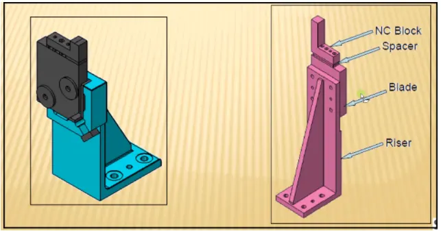
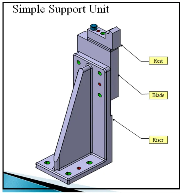
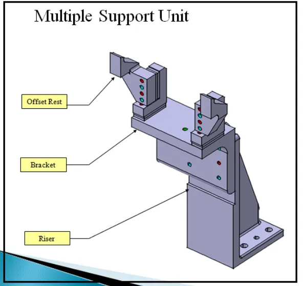
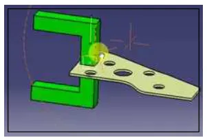
a)Mylar/NC blocks/Fingers: These are parts used to hold panel. They are globally called as Mylar top side mylar is called clamping mylar & bottom side is called resting mylar every clamping should have resting mylar. It is jaw type. It prevent panel from deforming while welding it is harden to increase its wear strength.
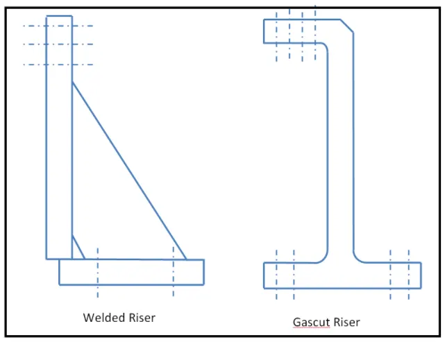
b) Riser: Riser can be L- type welded or square tube or frame type.These are basically manufactured parts are used to given height to assembly. It is machined at mounted ends only to save cost.
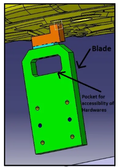
c) Blade: These are plates mounted on the riser.Other parts like cylinder,arms etc are mounted on the blade.
d)Shims/Spacer: In fixture , we are providing tolerance to each part mostly manufactured.Those tolerances tend to stack up & reflect together.In order to avoid that we use shims so we can easily adjust after assembly so whatever stack up there we will rectify it through shims.Shims come in thickness of 0.1,0.2,0.5 etc.
15) What are the basic fundamentals to design a sensor unit?
Answer:-
Sensor unit: It is designed to sense car panel using electrical sensor. This signal the sensor will be fed to the PLC & so next process will be excuted. Sensor unit are used actually in sensing whether panel are there or not or particular component are there or not. Suppose there are 9no's of par require for assembly then we have that no.of sensor at least.Whenever operator manually assemble entire component they do the process like fastening, gluing.The sensor will show that particular component is there or if component is missing it will give an error.
Fundamental of sensor unit design:
- Every signal loose panel which are being welded in tool.
- Each panel should be sensed by 1 or 2 sensor depends on size of panel,preferred to be in diagonal opposite ends of panel.
- Every sensor should be mounted in 3 directions adjustable way in general.
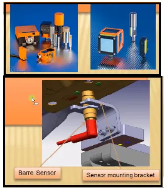
- Some major sensor manufactures are IFM, Pepperi-fichs,SICK,OMRON etc.
Types of sensor used in general.
Proximity sensor- It has sensing range 5 to 6 mm. It is based on magnetic field principle.A proximity sensor is a sensor able to detect the presence of nearby objects without any physical contact.
A proximity sensor often emits an electromagnetic field or a beam of electromagnetic radiation (infrared, for instance), and looks for changes in the field or return signal
Photo electric sensor: A photoelectric sensor is equipment used to discover the distance, absence or presence of an object by using a light transmitter, often infrared, and a photoelectric receiver. They are largely used in industrial manufacturing.Below fig shows.
16) What is rough locator unit& what are the basic fundamentals to consider while designing it?
Answer:-
Rough locators: Rough locators
Fundamental of rough locator design.
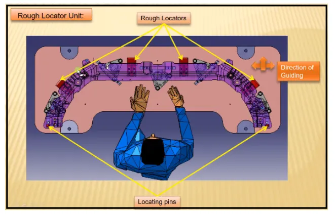
- Rough locator be palced at the edge of car panel , which it has to guide using locating pins one easily restrict movement of entire car panel .
- Rough locator has to be placed in the same angle of the car part edge with minimum distance of 2.5mm from the edge of car part, so it should no damage panel.
- Rough locator should guide the before 10 to 15 mm.to the start of the pin engagement .
- Rough locator should guide in pin arresting in genral .
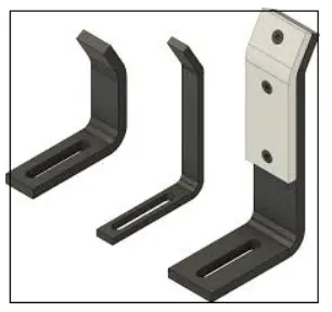
- Rough locator should be designed with two slots to mount for easy adjustment.(in genral)
- The slot should be in the direction of car panel guiding .
17) What is base unit?And descibe its parts?
Answer:-
BASE UNIT:-
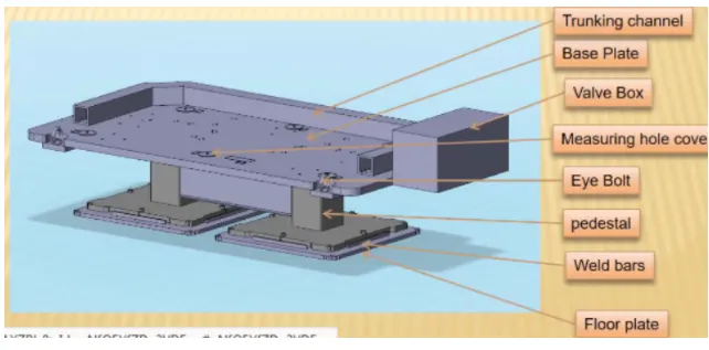
Base unit is the deisgned to mount all the other unit like clamp unit , pin unit , rest unit etc . of the tool, also other parts like pneumatic valve box, truck cable path will also be mounted on to a base unit.
PARTS OF BASE UNIT:-
Parts of base unit are as follows .
1.Valve box.
2.Trunking channel.
3.Measuring hole cover .
4.Eye bolt .
5.Pedestal.
6.Floor plates.
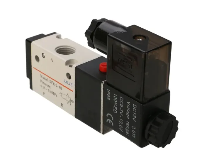
1.Valve box :-
Valve box is basically a box which suplies air to all the pneumatic cylinders assembled in the fixture.
Valve box consist of one solenoid valve is used to collect the sir from the pneumatic cylinder to valve box.
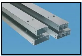
2.Trunking channel:-
Trunking channel is kind of cable duct ,which helps to guide and protect the wiring / tubes used in the fixtures.
3.Measuring hole cover:
In the measuring hole cover the coordinates point are engraved on it .
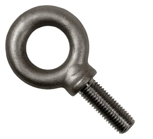
4.Eye bolt:
An eye bolt is a bolt with a loop at one end . They are used firmly attach a securing eye to a structure , so that ropes or cables may then be tied to it lifting purpose.
Eyebolt is used to frag or lift the base unit while relocting.
5.Pedestal:
Pedestal is a stand like structure where the enitire unit of base will be mounted .
6.Floor plates:
Floor plates is used to mount the enitire bse with the floor.
Also it helps to achieve the flatness of the fixture.
18) What is dump unit & what are its function ?
Answer:-
DUMP UNIT:-
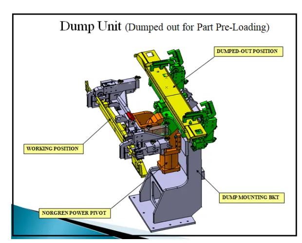
Dump unit is where you assembly component if you certain constraint. here you will have clamp unit attached & panel will be assembled . so if you have certain constraint you cannot assembly in normal way.
Dump unit use in different way . it has dump cylinder & complete design. it consists of dump cylinder to perform of clamping & unclamping car panel . A dump unit can have more then one cylinder to perform such operation.
The first cylinder dumps the assembly carrying clamp mylors , pins and then this assembly perform the required operation . In this unit , we should make sure that in the open position of panel , we should be able to remove the panel . below fig. show dump unit.
19) What are slide unit ? Mention where slide unit are commonly used ?
Answer:
Slide units:-
Slide unit are positiong unit , where are used to position the car parts or panel. unit , weld gun , robots for further operations
Slide unit may be classified into type based on the type of guide ways . They are.
1.hardend guide way.
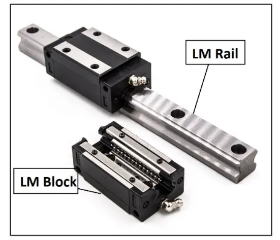
2.LM guideway.
Slide units may be classified into three type bassed on the prime mover.They are.
1.Manual slides .
2.Hydraulic/ pneumatic slides.
3.CNC slides.
it may be futher classified depaending on the appliaction as
1.Horizontal slide unit.
2.Vertical slide unit .
3.Angular slide unit.
Basic Fundamentals of slide unit design:-
Reverse stroke 10mm to be cosidered in both forward & retracted condition cylunder & LM guides to be load & stroke.
Master guideway should be constrained & the subsidiary guideway to be free .
Mechanical hard stop to be used for both extended & retracted cindition .
shock absober should be used for both extended & retracted condition to reduce impact load.
Slide to be locked / clamped in the working position
slide to be locked / clamped in the working position .
Slide to be locked with a safety pin in the retracted position during tranportation.
The two end limites to be sensed externally by a proximity switch.
The design should be checked for screw accessiblity , ease of assembly machinability of parts.
The LM guide & reails are integral assemblies and should not be separated at any cost LM guide way to be lubricateed for long life
Sliding unit are basically use in places where you have certain constraint , space constraint, some there are too many panel near each other and there is not enough space as each panel requires location using 2 pin , clamping and sensing . This becomes even more difficult when panel is at angles. To solve this problem a slide unit mounts rest , clamp or pin unit or all of them on a slide using guide rails, giude block , a cylinder , locking mechanism . stop blocks and sensors . when a particular panel is to be welded this moves forward , fixes the panel and on completion of operation , side moves back and gets locked at its position . similarly . the same is done for other panels.