Week 3:- BiW Fixture Design Methodologies Challenges
- What is design methodologies?
Design methodology is the process followed to make the design process smooth and easy to understand by all. The steps followed in design methodology includes things like structuring the tree in a particular way, naming the tree in a particular way for it to be easy to understand for any person who hasn’t worked on the entire design process from scratch.
There are various steps to it, which are as follows-
- Purchase order: PO is like a conformation document that the design concept needs to be started. The first thing that needs to be done after PO is to prepare a schedule to allot time frame needed to complete the project at the earliest and within deadline. A PO usually consist of the cost of the products the customer needs to out-source along with quantities, types, etc.
- Inputs from customer: There is various data that needs to be specified by the customer before starting work on the design.
- Functional Requirement
- Preferred Standards
- Car Products
- Layout
- Ergo Data
- Weld Study
- Standard detailing templates
- Percentage of completion criteria: once the concept design is finalized the project is believed to be 25% completed. The next step is checking the fixture and running it through simulation after approval from customer. After the simulation the project is believed to be about 40% complete. Next, after the design is fixed after improving it from the simulation results, detailing of the drawing needs to be done. After it’s done, the project is about 85% complete. Only after the final dispatch the project can be said to be fully complete.
- Design output: the most important part of project completion is to provide the customer with proper documents of the project, it is physical evidence that the project as been done by us. The documents include, bill of material, 3d documents, 2d drawings, etc.
- What are the inputs required from the customer to start designing a fixture?
Inputs from customer: There is various data that needs to be specified by the customer before starting work on the design.
1.Functional Requirement: The function the fixture needs to perform. The customer needs to define what operation the fixture will be doing (gluing, riveting, welding, etc.)
2.Preferred Standards: Different companies follow different standards. However, there are a few standards that are usually followed by most companies like ABB, NAAMS, DESTACO, ZYTRAN, TUNKERS. Following standards from the get go, helps in minimizing the time required to organize the data later and is easier to maintain as well.
- Car Products: Data like CAD part files, clamp plan, GDnT etc.
3.Layout: It gives an idea of where all the units will be placed. It gives the coverage area of units like tool changers, sequence of the operations, etc.
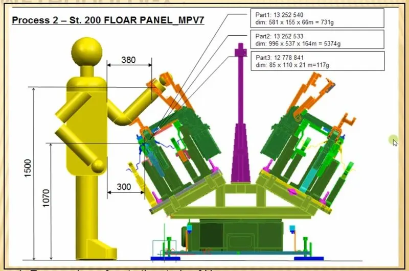
4.Ergo Data: Ergo data is usually needs to make sure the operator is not stressed to much physically in case of operating and working on manual fixtures. It provides inputs like ideal height, clearance, minimum/maximum height of fixtures etc. It provides data of working safety zone of the operators to keep them safe from potential harm.
5.Weld Study: It is one of the most important inputs given, includes details of study of gun that will be used in the welding process. It also includes the amount of weld points needed, gun details, etc.
6.Standard detailing templates: it includes details of the cad drawing as per the customer requirement. After the finalization of the drawing, the drawing needs to be submitted as the given template.
3.What is the inputs we get from car products?
1.GD&T: It includes information of locating pins, and other various units’ information. Information of opening and closing of clamps, various strokes are also added to the data. Tolerance information is important as the parts will be later assembled and stack up tolerances might cause problems; hence tolerance data is important. It also helps make the parts interchangeable, so that if any problem arises later, it is easy to replace.
2.Part list: The list contains the details of all the parts along with the part name, number etc.
3.3D cad files: the files of the BIW needs to be sent the customer so that the pins are designed in the right location and of the right size for the assembly. The file is usually sent in. igs or .stp format as it can be accessed through any software.
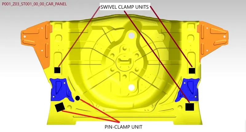
4.Clamp Plan: it includes the information of the pins, rest units, dump units, etc. it is an important piece of information and should not be changed without confirming the customer first.
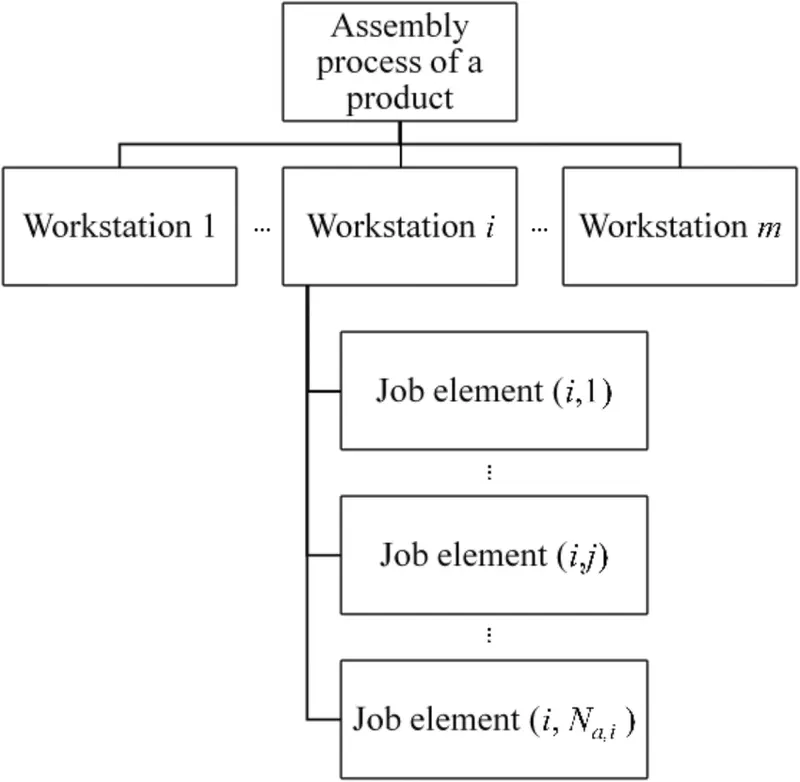
5.Product assembly process sheet: It gives information of assembly of the parts. It shows the step-by-step process of how the parts are assembled together starting from the very first part to the very last one.
- What is a clam plan?
Clamp is a device which is used to secure the position of a part so that it stops moving in a particular direction. It used pressure on the parts so that they aren’t separated or moved during operation. The time for clamping should be less so that there is no delay in the work. The part should not vibrate or moving when the operation is going on.
Clamp plan:
- The given data in the plan, should not be changed.
- It gives the information of where exactly the clamp needs to be placed while working on a part.
- The clamp data is usually based on previous studies and hence should not be changed without confirming with the customer.
- What is the purpose of the layout?
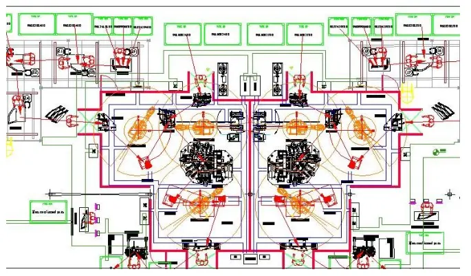
The layout is information about the placements of the robots, the working area they cover, the fixtures positions, etc. Layout shows the entire assembly plan of the project to understand the flow of the process.
A circle around the robot indicates the swept are of the robot and can give us an idea how many robots work at the same workstation as well as a robot is working on how many stations. It comes with details like robot stations, tool changing stations, sub assembly links etc.
Layout gives us a brief idea about how the parts will be assembled and moved forward through the assembly line. Information such as distance between two stations is important as it can be crucial in deciding which type of fixture is to be designed for it and hence, is added to the layout.
Based on the layout, the design engineer develops a concept sketch of fixtures. The main idea behind providing a layout is to avoid clashes in the entire assembly.
What is Ergo-Data?
Ergo data is the inputs related to the human dynamics of engineering. It is the way the human and the work tool will be interacting. Ergonomics or human engineering is the study of exactly that.
The need for ergo data is as follows:
- To increase efficiency of the work by reducing discomfort cause by physical fatigue while working with the product.
- To make the work environment safe for the operator which helps reduce stress while working.
Ergo data is needed when the fixture is manually worked upon. Ergo data is provide by the customer and the standards needs to be followed accordingly. It has information related to how the operator and the working environment will interact.
The work of the design engineer is to study and understand these inputs and design a fixture which is safe as well as comfortable for the operator. This not only reduces the stress physically and mentally on the operator but also improves efficiency of the work as the operator tends to tire out less.
- What do you understand by weld study?
It is another on the inputs by the customer. It provides the details of the weld gun the customer will be using for the assembling of the components. It gives the details of the weld gun along with weld matrix and weld spots.
The geo spots i.e., the most important spots are generally shown in red spheres and the re-spots are shown in green. These color codes help with deciding the coverage of the fixtures on with the robots will be placed.
- What are the criteria for percentage completion in designing stage?
There are 4 stages to completing the design project of the fixtures, which are as follows:
- Input and concept design: Once the design inputs are in, the design engineer starts working on the concept design of the fixtures. The input consists of the weld study which is needed for deciding the reachability of the fixture, then there is ergo data which is needed to help design the fixture which is safe and comfortable for the operator. After the concept design is ready after studying and understanding the inputs, the project is said to be about 25% complete.
- Concept approval and simulation check: After the concept design is ready, it is checked by the customer for if it is fulfilling their requirement or not and if there are any changes required, they are then added to the design, once the concept design is ready according to the customer, simulation tests are done to check the feasibility of the design. According to the results the design is modified. The project is understood to be about 40% complete at this stage.
- Design freezing and detailing: Once the design is locked, there are other procedures which are important. The 2D and 3D detailing of the design is important and this documentation work is important. After the detailing is done the project is about 85% completed.
- Check and final dispatch: After all the detailing, all the documents and files are checked for any errors so that a proper and error free project is delivered to the customer. Once the check is complete, the fixtures and documentations are then dispatched to the customer. Only after successful dispatch is the project believed to be 100% completed.
- Brief about Output of design?
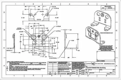
Once the design is freezed, it needs to be properly documented. The detailing of all the parts is done in 2D drawing, which are broadly divided in two parts. Detailing of Utilized tool and non-Utilized tool. The document needs to have details like bill of material, positions of all the parts, etc.
There are 2 types of sheets for utilized tools. One is key sheet which includes the isometric view as well as orthogonal view of the parts of the assembly of a particular fixture. Along with BOM. The other type of sheet is called as layout sheet. It gives details like number of units in a project, their positions etc.
Only one sheet is usually enough for non utilized tools which gives details of all the tool changers or stands.
Following points need to be kept in mind when finalizing design:
- Standards need to be followed when designing.
- Design must follow ergonomics basics.
- Clearance and accessibility of maintenance and service must be allowed in the design.
- Motion control for moving components.
- The designer needs to make sure the clamps and weld points are correct.
- What do you understand by structuring the design tree? Why is it necessary?
Structuring the tree is when all the assemblies and parts of the assembly are named and added to the tree in a proper sequence. Different companies have different standards that they follow.
When looking at an assembly it is necessary to identify which part belong to which assembly and unit. For this naming the components in a particular way help reduce search time and making it easy to spot. Naming a part correctly should give information of what the part is, which assembly it fits in and what unit it belongs to.
If the part is misnamed, then it might accidently be placed with a different assembly where there is no use of it, the assembling operator will then be confused as to how the assembly needs to be done and the work is then delayed.
The products should follow a pattern similar to this: P001_Z03_ST09_01_00_R.
Where,
- P001 indicates the project in which the part is used.
- Z03 indicates the zone where the part belongs.
- ST09 is the station where the part works.
- 01 is the unit’s name.
- 00 is the part number
- R is the left or right-side fitting in case it is a mirrored component.
The fixture might follow a different standard which is similar to the above method: H1L_19A_RFFRA_JG3_01_00_R
Where,
- H1L_19A is the project name.
- RFFRA is the panel name or zone in the above example.
- JG3, JG stands for jig-3 it the short forms for different units like clamps might be different but follows similar pattern.
- 01 is the unit’s name.
- 00 is the part number.
- R, whether the part fits in the left or right side.
- What are Units? Mention 5 types of units.
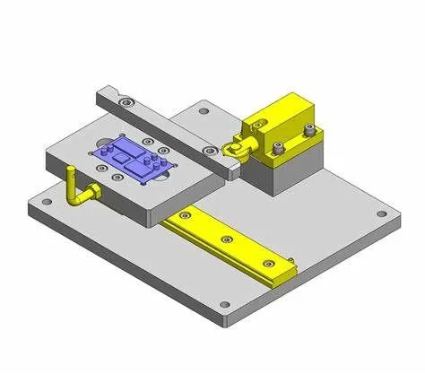
Units are assemblies that have a specified function. A fixture has different types of units for different functions.
For example, for a typical weld fixture the units are rest unit, fixed pin unit, retract pin unit, rough locators, sensor units, base unit. Similarly, for a complex unit there are added units like dump unit and slide unit.
Some of the types of Units:
- Base Unit: It holds all the other units such as clamp unit, pin unit rest unit, etc. it provides a height for the fixture which is needed in terms of ergonomics.
- Fixed Pin Unit: It is a locating unit. Parts like pins, retainers, shims, blocks, blades are part of this unit. It is used to locate the workpiece at the correct place for operations like welding, riveting etc.
- Sensor Unit: It consists of sensor for detecting the distance or the presence or absence of a workpiece during operation. It helps is keeps the equipment safe and early detection of any problems as sensor quickly indicate any problems.
- Clamping Unit: It is used to hold the workpiece when any operation is going on or to keep the workpiece stable. Clamping of the part is either done by leaver or pneumatic cylinders and clamp arms. Riser, arms, shims, resting clamp all are part of the clamping unit.
- Slide Unit: In case of space constrains, slide units are the best solution as it takes up less space. But slide units are complicated to design as well as costly to manufacture. It requires a rail to guide the slide. The generally as a stopper as well so that it stops at the right position.
- Describe fixed pin unit and their purpose.
Fixed pin unit is a locating unit, used to locate the panel position. Retainers are used to hold the pin firmly. Pin accurately locates the workpiece for welding process as well as helps arrest max 4 degrees of freedom and min 2 degrees. The pin should be fully constrained to prevent movement.
- What are the different parts of the fixed pin unit?
A pin unit consists of the following:
- Pin: The pin which goes through the workpiece and helps locate the workpiece. The pin arrests the movement of the workpiece. There are mainly two types of pins, diamond type and round pins. If it’s a slot then a diamond pin can arrest 4 degrees of freedom and a round pin can arrest 2 degrees of freedom. If it’s a hole, a diamond pin arrest 2 degrees of freedom and a round pin can arrest 4 degrees of freedom. These pins can be screwed or threaded.
- Pin retainer: It hold the locating pin and can also be called as the resting part of the pin. A counter hole is usually drilled on the retainer to fit the pin.
- Shims: Shims are very important part in any type of units as they help reduce the errors caused by stack-up tolerances. Shims are usually provided in two directions so that stack up tolerance can be adjusted according to need. There are various types of shims like plastic, metal, wood etc. It depends of the function and which part of assembly it goes in and what work environment the unit works in to choose which type of shims to be bought.
- Riser: It provides the right height required for the pin to located the workpiece correctly. It can be an L-type riser or a square type riser.
- Blade: It is needed if there is a need for pneumatic cylinder to be attached to the unit.
- What is purpose of making rest unit? And describe its parts.
Rest unit is used to support the car panel using resting clamps, there are only resting clamps and not clamps from upper side to clamp the panel.
A resting unit has no other functions hence it is usually combined with other units to reduce cost. Rest unit can be of various types like simple supports, retractable supports etc.
Rest unit consists of the following parts.
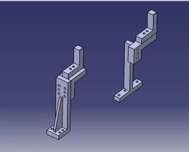
- NC blocks/Mylars: It is also known as fingers and is used to hold the workpiece of support the workpieces depending on the use. Depending on the use of the mylars, it can be ca clamping mylar or a resting mylar. Clamping mylars are above the workpiece and aligned with the resting mylar. The resting mylar is supports the part from below and the workpiece rests on the resting mylar.
- Risers: It is used to provide height to the mylar. It can be either L-type riser or square tube riser. The resting mylar is attached to the end of the riser.
- Blade: blades are attached to the risers and are used for mounting of cylinders or arms etc.
- Shims: Shims are important parts in any unit as it is used to adjust the stack up tolerances of parts of the assembly. This is required as stack-up tolerances might cause the part to be held loosely of tightly which is not desirable.
- What are the basic fundamentals to design a sensor unit?
There are various sensors used in fixture design, usually to detect the presence of the panel. The signals from the electrical sensors are sent to the PLC and further actions are decided depending on the role and importance of the sensor.
Basics of sensor:
- Sensors should be placed such that it covers maximum area of the panel.
- The sensors should be adjustable in all 3 directions.
- Loose panels should always be detected my sensors.
Types of sensors generally use are: Proximity sensors, Laser sensors, Photoelectric sensors.
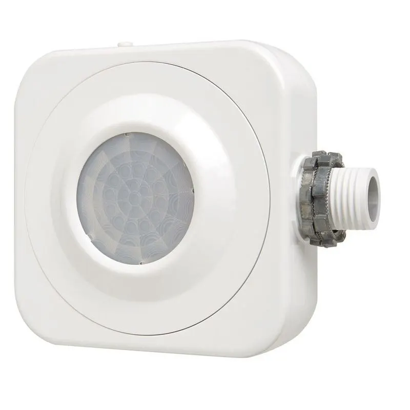
Occupancy sensor in fixture.
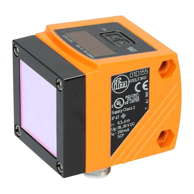
Laser sensor
- What is rough locators are the basic fundamentals to consider while designing it?
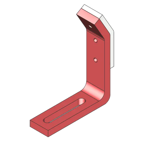
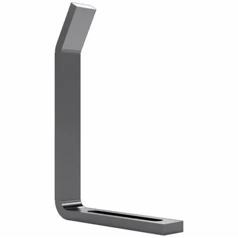
Rough locator helps the operator by indicating the area in with the panel is to be mounted. It can be a standard part of a make part.
Fundamentals:
- Rough locators should be placed at the edges of the car as a guide.
- Rough locators should be easy to adjust.
- The slots provided should be in the direction of the panel.
- Should be at a minimum distance of 2-5mm from the car panel edge.
- Should guide the panels such that it easily fits in the pin locators.
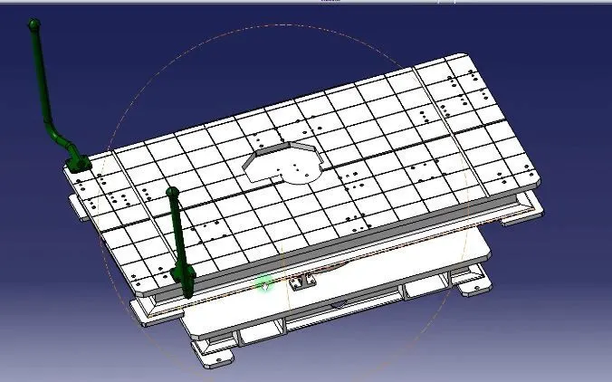
- What is a base unit? Describe its parts.
Base unit carries all the others units like clam, pin unit, tool etc. on it. It also carries parts like valve box, cables, channels etc.
Parts of base unit:
- Valve box: It supplies air to the pneumatic cylinders mounted on the base unit. It consists of solenoid valve.
- Trunking channel: Trunking channel is kind of a cable duct used to cover all the cables required for the units on the base unit. It provides protection to the cables as well as makes the assembly look neater.
- Measuring Hole cover: It gives the coordinates of the nits that need to be placed on the base unit.
- Eye bolt: It is used to help hook the base unit for lifting purposes or even guide the cables.
- Pedestal: It is a stand like structure where the entire unit of the base will be mounted.
- Floor plates: It is used to mount the base on the floor.
- What is a dump unit and what are its functions?
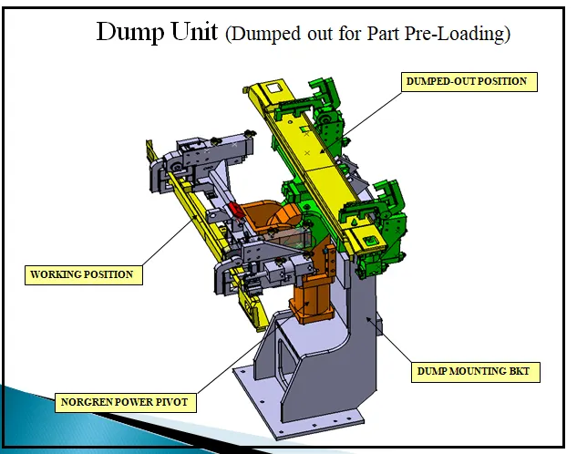
It is the station where components are assembled if there are some constraints to work with. Dump unit has a complex design, it has all the components like dump cylinder and complex design. It consists of dump cylinder to perform operation of clamping and unclamping if car panel. A dump unit performs al the necessary operations like loading and unloading clamping and performing required operations.
- What are slide units? Mention where slide units are commonly used?
It can be called as positioning units as well. It can be used to position the panels, weld guns, robots for whatever operation it is needed for. It is generally of 2 types, hardened guide way and LM guideway. Slide units may further be classified into three types based on the prime mover. They can be manual slides, hydraulic slides, pneumatic slides or CNC slides.
Depending on application we can be horizontal, vertical, angular slide unit.
Slide units are usually used in complex fixtures. It is used in areas where there is limited space to work. It makes the welding process easy, it helps is better and faster positioning of parts like weld guns, ins, etc.