Week 3:- BiW Fixture Design Methodologies Challenges
Q.1
|
What is Design Methodology? |
Answer:-
Design Methodology:-
In this section, we will learn about some basic manufacturing parts, which are commonly used in the BIW fixture design. Very commonly used parts are Mylar, Pin, Blade, L Block, Pin Block, Riser, Weldment, etc.
Before we go to these parts we should know about shimming and should know how it works.
Shim is a set of thin plates (2 mm, 1mm, 0.5 mm, 0.25mm) that are used to adjust the gap or used for a better fit. Shimming can be of thickness 5mm, 8mm, or 10mm. In case no proper fitting between mylar and Panel due to manufacturing errors then this error can be removed using shims. Shims are placed in the carline position so that gap can be adjusted in the required direction like X, Y, or Z.
There are three types of shimming. These are one-way, two-way, and three-way shimming.
Number of shimming depends upon the NC cut angle and PIN angle with the car line.
If the NC cut is less than 15 deg then mylar will have one-way shimming.
If NC cut is more than 15 deg in one direction then mylar will have a 2-way direction shimming
If NC has more than 15 deg angle in two directions then mylar will have 3-way directional shimming.
But in the case of pins, this case is a bit different. If the pin is on the angle with respect to the carline and that angle is not more than 15 deg then the pin will have 2-way directional shimming, if Pin’s angle is more than 15 deg in any direction then 3 shimming will be used.
MYLAR :
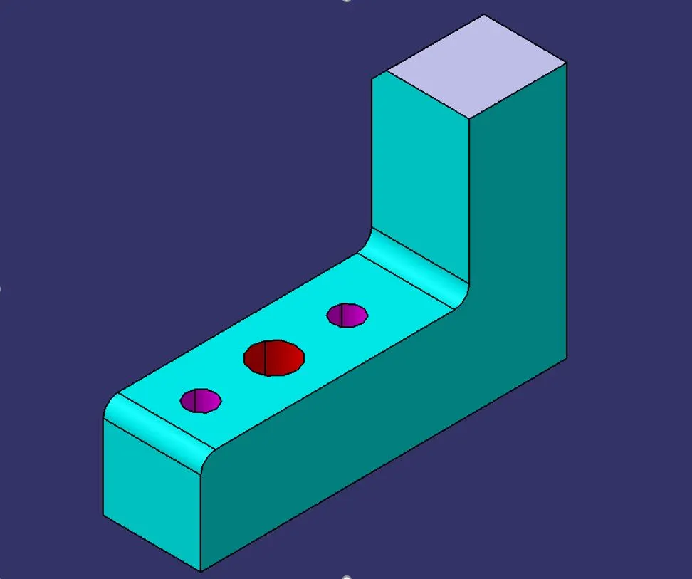
MYLAR is one kind of block that touches the panel and holds or clamps the panel. Mylars are always designed in CAR LINE. Mylar is also called the NC(Numerically Controlled)Block. Mylars are mounted on any block or plate with Shimming, So that height of mylar can be adjusted accordingly at the assembly level. For ‘A’ class surfaces Nylon mylars are used. So that surface can be saved from scratches.
Shimming can be 1 directional, 2 directional, or 3 directional as per the NC cut.
PIN:
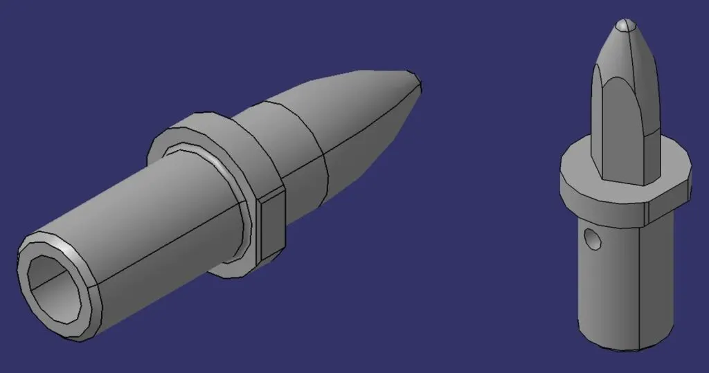
Pins are used to lock the rotational movement of the panel. Generally there are two types of Pins, one is a Round Pin and another one is a Diamond pin. We use two and three-directional shimming for pins as per the angle of the pin w.r.t. the carline. In some cases, we use a collared pin, when the pin is supposed to support the panel as well. For this kind of pin, we provide 3 way shimming irrespective of pin angle to the carline.
BLADE :
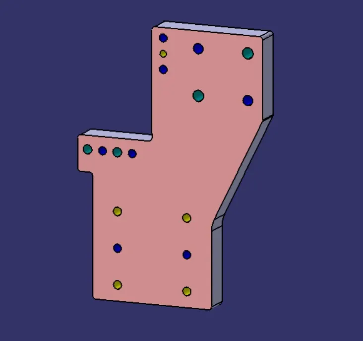
The plate which connects Riser to the Clamp cylinder is named Blade. This plate plays an important role in building the unit. The plate can be of any shape. But we need to keep in mind that the plate should be as compact as possible.
L BLOCK :
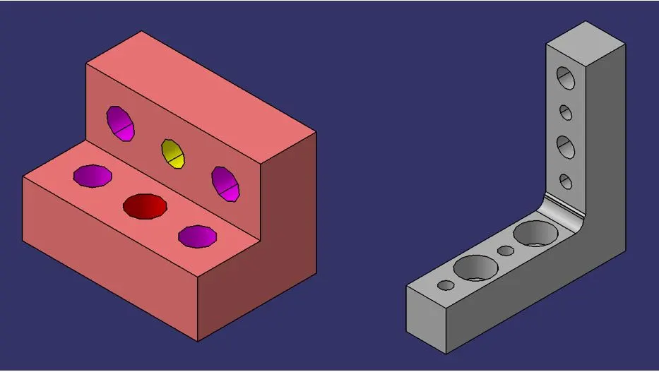
A plate shaped as L is called an L block. This part is used as a connection between mylar and Blade. Generally, L blocks are used to provide shimming. It is not necessary that L blocks are only used for shimming, its use changes as per the requirements. At some places, it is used just to connect one part to another. Similar to the L block one more block is used which is in the shape of T. So this block is called a T Block.
PIN BLOCK :
Pin Block is also called Pin Retainer. This block holds the pin and restricts the rotational motion of the pin. Pin Block can be either manufactured one or Standard.
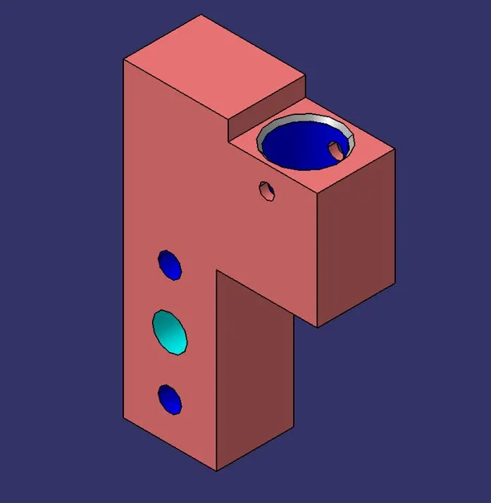
RISER :
The part which is mounted on the base plate and holds a clamp or pin cylinder on it, is called Riser. Riser can be Standard Part or manufactured part, it varies from project to project. A riser can be a Single part or welded part. Standard risers also have various shapes and sizes.
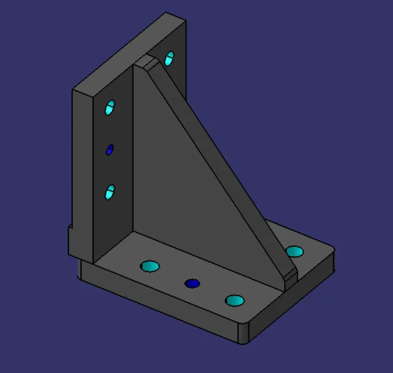
WELDMENT :
Weldment is the assembly of two or more parts that are joined by welding. To make a weld it is the thumb rule to have a 5 mm overlay on each other plates so that space can be provided for welding. A weldment can be of any size and any number of plates.
Q2. What are the inputs required from the customer to start designing a Fixture?
To design a fixture, the following inputs are required from the customer :
-
Drawing of the component: The drawing should contain all relevant dimensions, tolerances, surface finish requirements, etc. of the component to be milled.
-
Material and geometry of the workpiece: The material and geometry of the workpiece should be analyzed to conceptualize a basic fixture configuration.
-
Operations required: The operations required to process the workpiece should be analyzed to determine the type of fixture required.
-
Processing equipment for the operations: The processing equipment required for the operations should be analyzed to determine the type of fixture required.
-
Operator: The operator should be analyzed to determine if any special requirements are needed.
Once these inputs are available, a fixture plan can be conceptualized through analyzing all available information . The fixture plan includes a basic fixture configuration and outputs such as:
-
Locators: A fixed component of a fixture used to establish and maintain the position of a part in the fixture by constraining its movement.
-
Clamps: A force-actuating mechanism of a fixture that holds a part securely in the fixture against all other external forces.
-
Supports: A fixed or adjustable element of a fixture that prevents or constrains deformation when severe part displacement/deflection is expected under the action of imposed clamping and processing forces.
-
Fixture body: The major structural element of a fixture that maintains the spatial relationship between locators, clamps, supports, and the machine tool on which the part is to be processed.
Q3. What is the input we get from "Car Products"?
Answer:-
Cars are made of a wide variety of materials, such as steel, aluminum, copper, glass, rubber, and special fibers. First, a raw material production company takes individual raw materials and turns them into materials that can be used to make car parts, and delivers them to parts production companies or to Toyota.
What is the manufacturing process of automotive?
Stamping is the beginning of a vehicle’s manufacturing process and involves converting the raw materials received in the form of steel sheets into body parts. Sheet metal is the second step in the manufacturing process and involves joining the sheet metal and aluminum parts together to form the box.
What is a car input?
If we take the example of a car. The input energy is the fuel, petrol, which is chemical energy. The engine changes the energy to kinetic energy and the pistons move up and down. But the amount of energy which comes out of the system is much less than the input.
Is a car motor an input or output device?
Scientifically speaking, the electric motor is a unit used to convert electric power into motive energy or electrical energy into mechanical energy. Electrical input may be simply shortened to read input, and mechanical output (motive energy) can be simply shortened to output.
What are the basic inputs of the manufacturing processes?
In process manufacturing, the basic inputs (natural resources, raw materials) are broken down into one or more outputs (products). For instance, bauxite (the input) is processed to extract aluminum (the output). The assembly process is just the opposite.
What is stamping in car manufacturing?
In the automotive production process, one of the processes in production is stamping. Stamping (also known as pressing) includes a variety of sheet-metal forming manufacturing processes, such as punching using a machine press or stamping press, blanking, embossing, bending, flanging, and coining [2].
What are the major process steps in the assembly of automobiles?
… three main stages of an assembly line in the automotive industry are: the body shop, the paint shop, and the trim and chassis shop. Cars flow through the assembly line from stage to stage in sequence (see Figure 1). …
What is the input process output of a car?
What is the Input Process Output of a car? The input process output of a car identifies its inputs, outputs, and processing. In some cases it has a storage component. How much does an PLC have outputs and inputs maximum?
What are the inputs and outputs of manufacturing?
Figure 1 shows the input, process, output and control model for manufacturing. The system’s inputs are knowledge and skills of people combined with tools and materials. The output, products and byproducts, result from the type of processes used to change the system inputs.
What is the function of a manufacturing system?
Manufacturing System Model The function of a manufacturing system is to transform materials into useful products. The manufacturing systems model consists of four subsystems; input, process, output and control. Figure 1 shows the input, process, output and control model for manufacturing.
What’s the production process of a Toyota car?
Toyota Production Process The system of production Toyota is an integral system of production and management arising in Toyota Company. In origin, the system was designed for factories of cars and his relations by suppliers and consumers, though it has spread to other areas.
Q4 What is the Clamp plan?
Answer:-
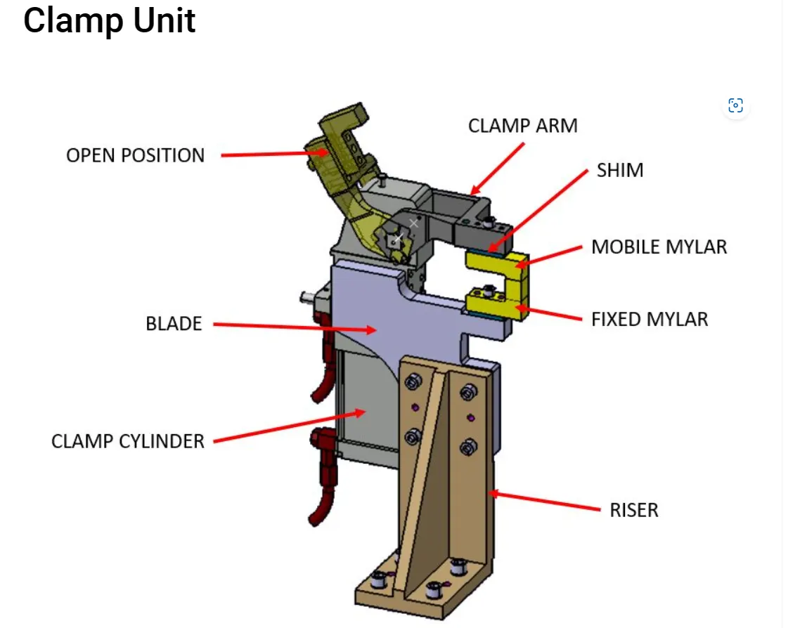
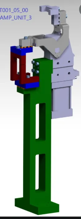
A Clamp Unit is used to lock the panel position in a transitional direction. It supports the panel with fixed Mylar and locks its movement with mobile Mylar, when panels come onto the tool then clamp is in open condition once panel sits down then clamp closes and joining process is done. Once the joining process gets completed, then the cylinder arm opens. Complexity of the unit depends upon the gun reachability and panel area. Given picture is just an example of a simple clamp unit.
Q What is the purpose of a Layout?
Answer:-
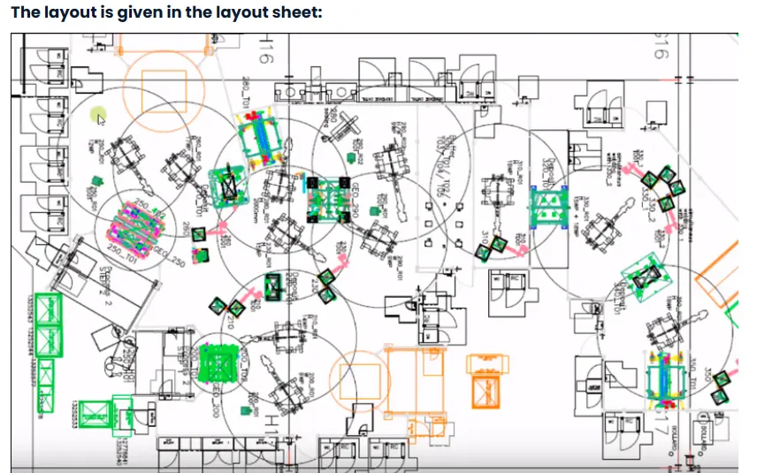
The layout provides the following data:
-
Flow parts
-
Pitch station
-
Robot layout
-
Tool changers and tip dressers
-
Sub assemblies links
-
Platform height
-
Loading and unloading sequence
Q:-What is Ergo data?
Answer:- The ergo data is the data provided for the safety and the comfort of the worker who will operate the fixture manually. This contains the data like height of the worker, distance that the worker will stand from the fixture, the angle at which his/her arms should bend.
Q:-What do you understand by Weld study?
Answer:-Welding involves a high skill level and practical knowledge of subjects like physics, chemistry, and metallurgy. Welding is generally done on metals but is also used for fusing wood or thermoplastic parts. A completed joint is a weld joint or weldment.
Q:-What are the criteria for percentage completion in the designing stage? Explain it in detail
Answer:-
The percentage completion criteria in the designing stage vary depending on the project and the organization. However, in general, the design phase of a project can be divided into four stages: pre-design, schematic design, design development, and construction documents . The percentage completion criteria are usually established for each of these stages.
During the pre-design stage, a project program is developed that defines the scope and budget of the project . The percentage completion criteria for this stage are not typically defined.
In the schematic design stage, the design professional develops a preliminary design that outlines the general layout, scale, and relationship of the project’s components. The percentage completion criteria for this stage can range from 10% to 50% .
In the design development stage, the design professional refines the schematic design and develops detailed drawings and specifications .The percentage completion criteria for this stage can range from 50% to 90%.
Finally, in the construction documents stage, the design professional submits construction documents for review by the university and others as deemed necessary by the university. The percentage completion criteria for this stage can range from 90% to 100%.
It’s important to note that these percentages are not set in stone and can vary depending on the project’s complexity and size. Additionally, some organizations may use different percentages or different criteria altogether. Therefore, it’s essential to consult with your organization’s guidelines or consult with an expert in your field to determine specific percentage completion criteria for your project.
Q:- Brief about "Output" in design?
Answer:-Output Design:-
The design of output is the most important task of any system. During output design, developers identify the type of outputs needed, and consider the necessary output controls and prototype report layouts.
Objectives of Output Design:-
The objectives of input design are −
-
To develop output design that serves the intended purpose and eliminates the production of unwanted output.
-
To develop the output design that meets the end users requirements.
-
To deliver the appropriate quantity of output.
-
To form the output in appropriate format and direct it to the right person.
-
To make the output available on time for making good decisions.
Q:-What do you understand by structuring a design tree? How does it reduce errors during the design process?
Answer:-
Structuring a design tree is a process of organizing the design elements in a hierarchical manner. It is a visual representation of the design process that helps to break down the complex design into smaller, more manageable parts. This approach helps to identify the relationships between different design elements and how they interact with each other. By structuring a design tree, designers can easily identify the areas that need improvement and make changes accordingly.
Structuring a design tree can help reduce errors during the design process in several ways. Firstly, it helps to identify potential errors early in the design process, which can save time and resources in the long run. Secondly, it helps to ensure consistency across different parts of the design, which can help to avoid errors caused by inconsistencies. Finally, it helps to ensure that all aspects of the design are considered and accounted for, which can help to avoid errors caused by omissions.
Q:-What are Units? Mention 5 types of units.
Answer:-
Units:
A unit is a device that has a specified function, especially one forming part of a complex mechanism.
A welding fixture is an assembly of different types of units.
As name refers, the different units will be only seen in the unitized tool.
A units are classified into two, they are,
Simple unit: In a simple welding fixture, the combination of these different units will be seen.
-
Rest unit.
-
Fixed pin units.
-
Retract pin units.
-
Rough locator unit.
-
Sensor unit.
-
Base unit.
Complex unit: In a complex welding fixture, in addition with some of the simple units these complex units will also seen
-
Slide unit.
-
Dump unit.
Five Types Of Units:
-
Base unit:
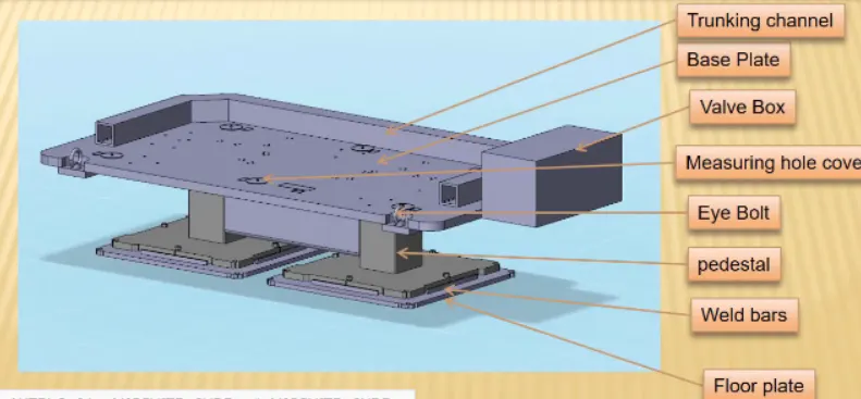
Base unit is the unit designed to mount all other units such as clamp unit, pin unit, rest unit etc., of tool, also other parts necessary for a tool like pneumatic valve box, trunk cable path will also be mounted on to be a base unit.
-
Fixed pin unit:
Fixed pin unit is a unit designed to locate the car panel using pins.table
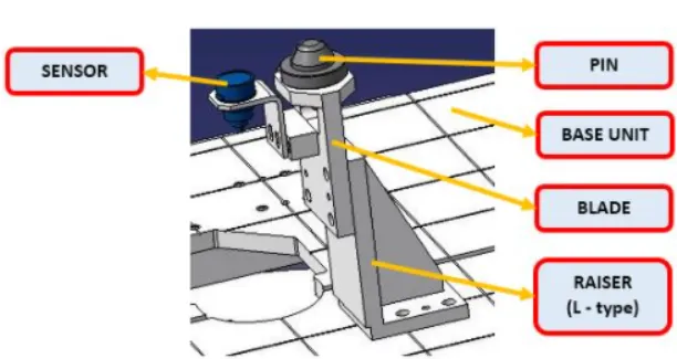
Pin, pin retainer, shims, blocks, blade, riser are the part of fixed pin units.
Pin retainer is used to hold the pin firmly.
Typically, the locating pins are used to locate a body part in a position sufficiently accurate to execute a welding process.
The body part is constrained by a set of appropriately locating pin so total constraint by locating pin should be fully constrained at all times to prevent any movement.
-
Retractable pin unit:
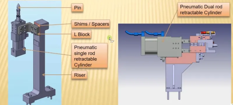
A retractable pin unit is a unit designed to locate the car panel using pins, but the entire pin package parts will be mounted on the retractable pneumatic cylinder as shown in below fig 3.
Retractable pin unit is the opposite of a fixed pin unit which can be moved up & down also which can be retracted till a certain distance.
It is mainly used for unloading the complex panel after welding.
-
Clamping unit:
Clamp unit is a unit designed to clamp or hold the car panel with NC block / Mylars by using a pneumatic clamp cylinder.
Clamping unit is used to clamp the part which is to be welded after location using a pin unit.
Clamping is achieved with the help of pneumatic cylinders and clamp arms.
Clamping arm, finger, rest, shims, standard riser, pneumatic cylinder are the parts of clamping unit in general.
Q:- Describe Fixed Pin units & their purpose?
Answer:-
A pin unit in which the pin's position is fixed, is called Fixed Pin Unit. Pin unit is used to lock the rotational position of the panel. Round Pin is used to control panels in two directions while Diamond Pin is used to control panels in one direction.
Q:- What are the different parts of a fixed unit?
Answer:-
DIFFERENT PARTS OF THE FIXED PIN UNIT: The different parts of the fixed pin units are as follows,
-
Pin.
-
Pin retainer.
-
Shims.
-
Blade.
-
Riser.
a. Pin:
-
It is used for the location purpose of the panel.
-
Typically, the locating pins are used to locate a body part in a position sufficiently accurate to execute a welding process.
-
The body part is constrained by a set of appropriately locating pins so total constraint by locating pin should be fully constrained at all times to prevent any movement.
-
There are dozens of styles of locating pins that can be utilized in a design. Below I have shown the commonly used pins.
b. Pin retainer:
-
Pin retainer is used to hold the locating pins firmly.
c. Shims:
-
In general, A shim is a thin and often tapered or wedged piece of material, used to fill small gaps or spaces between objects.
-
Shims are typically used in order to support, adjust for better fit, or provide a level surface.
-
Shims may also be used as spacers to fill gaps between parts subject to wear.
-
Shims are the small parts which come with the thickness of 0.1mm,0.2mm,0.5mm,1.0mm etc.
-
These will compensate for the stack up tolerance which reflects at the mylars.
-
We give tolerance to all parts of the fixture.Due to this tolerance the mylars will either lift up or move down from its defined position.
-
To adjust the mylars for getting the defined position we use shims.
-
Shims will be added above the mylar for adjusting according to tolerance.
d. Riser:
-
Riser is a manufacturing part used to raise/height the assemblies of fixtures.
-
One end of the raiser will be attached to the base unit while the other end will be attached to the Blade.
-
Raiser can be of two types.They are,
-
'L' type risers.
-
Square tube risers.
-
'L' TYPE RISERS: 'L' type risers are of welded type.Where the stiffener will be added at the center for support.As shown in the below figure the wedge shaped structure is known as stiffener which is used as a support / to withstand load.
e. Blade:
-
Blades are the plates which are attached to the raiser.
-
Blade is also attached or mounted with cylinders,arms etc.,
-
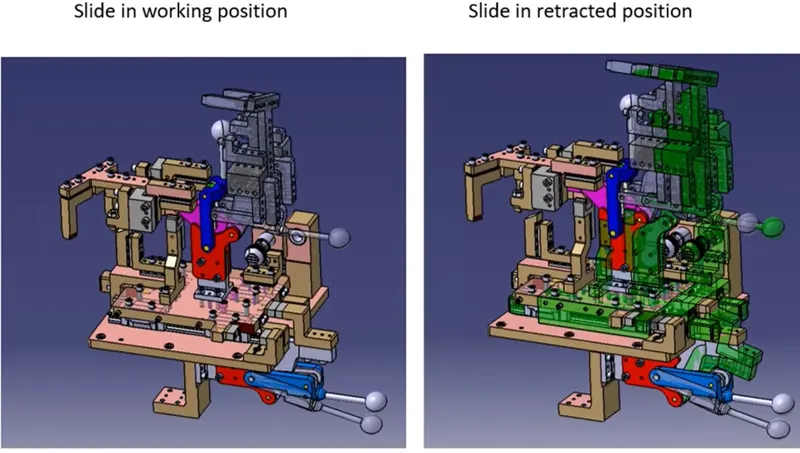
Slide unit:
Slide unit is found mostly in complex fixtures, where the sliding mechanism will be involved.
This type of unit is used when there are some space constraints.
Guide block, guide rail, position lock unit, stopper block, sensors are the parts of the slide unit in general.
Guide block & guide rail helps to guide the slide unit. The rail should always be covered to protect against weld spatter & dust by a bellow or a sheet metal cover.
Position lock unit helps the slide to be locked/clamped in the working position.
Stopper block helps to stop/control the entire moving of a slide unit from a certain distance, which is placed at the end of the guide rail.
Sensors – The two end limits to be sensed externally by a proximity sensor.
Q:-What is the purpose of making a Rest unit & describe its parts?
Answer:-A Rest Unit is a unit designed to support a car panel using Mylar/ NC block/ rest component is rested only, no upper clamp or force applied there. It is the simplest unit to design because it has fewer parts to design & the purpose is only resting on the car panel. The rest unit can be combined with another unit to reduce the cost of the overall project. It can be combined with a clamp unit to clamp as well as to rest the car panel. It can be combined with a locating unit to locate as well as to rest the car panel. Also locating, clamping & Test units can be combined together in one unit to reduce cost.
The following are the different parts of a Rest Unit:
-
Rest Mylar: A thin polyester film that is used as a support for the car panel.
-
Blade: A flat, elongated metal piece that supports the rest of Mylar.
-
Riser: A metal block that elevates the blade and rest Mylar above the fixture plate.
Q:-What are the basic fundamentals to design a Sensor unit?
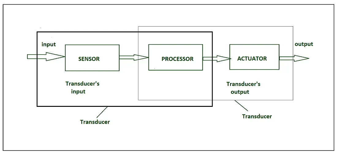
Answer:- Sensors are used for sensing things and devices etc.
A device that provides a usable output in response to a specified measurement.
The sensor attains a physical parameter and converts it into a signal suitable for processing (e.g. electrical, mechanical, optical) the characteristics of any device or material to detect the presence of a particular physical quantity.
The output of the sensor is a signal which is converted to a human-readable form like changes in characteristics, changes in resistance, capacitance, impedance, etc.
IOT HARDWARE
Transducer :
-
A transducer converts a signal from one physical structure to another.
-
It converts one type of energy into another type.
-
It might be used as an actuator in various systems.
Sensors characteristics :
-
Static
-
Dynamic
1. Static characteristics :
It is about how the output of a sensor changes in response to an input change after steady state condition.
-
Accuracy: Accuracy is the capability of measuring instruments to give a result close to the true value of the measured quantity. It measures errors. It is measured by absolute and relative errors. Express the correctness of the output compared to a higher prior system. Absolute error = Measured value – True value
Relative error = Measured value/True value -
Range: Gives the highest and the lowest value of the physical quantity within which the sensor can actually sense. Beyond these values, there is no sense or no kind of response.
e.g. RTD for measurement of temperature has a range of -200`c to 800`c. -
Resolution: Resolution is an important specification for selection of sensors. The higher the resolution, the better the precision. When the accretion is zero to, it is called the threshold.
Provide the smallest changes in the input that a sensor is able to sense. -
Precision: It is the capacity of a measuring instrument to give the same reading when repetitively measuring the same quantity under the same prescribed conditions.
It implies agreement between successive readings, NOT closeness to the true value.
It is related to the variance of a set of measurements.
It is a necessary but not sufficient condition for accuracy. -
Sensitivity: Sensitivity indicates the ratio of incremental change in the response of the system with respect to incremental change in input parameters. It can be found from the slope of the output characteristics curve of a sensor. It is the smallest amount of difference in quantity that will change the instrument’s reading.
-
Linearity: The deviation of the sensor value curve from a particularly straight line. Linearity is determined by the calibration curve. The static calibration curve plots the output amplitude versus the input amplitude under static conditions.
A curve’s slope resemblance to a straight line describes linearity. -
Drift: The difference in the measurement of the sensor from a specific reading when kept at that value for a long period of time.
-
Repeatability: The deviation between measurements in a sequence under the same conditions. The measurements have to be made under a short enough time duration so as not to allow significant long-term drift.
Dynamic Characteristics :
Properties of the systems
-
Zero-order system: The output shows a response to the input signal with no delay. It does not include energy-storing elements.
Ex. potentiometer measure, linear and rotary displacements. -
First-order system: When the output approaches its final value gradually.
Consists of an energy storage and dissipation element. -
Second-order system: Complex output response. The output response of the sensor oscillates before steady state.
Sensor Classification :
-
Passive & Active
-
Analog & digital
-
Scalar & vector
-
Passive Sensor –
Can not independently sense the input. Ex- Accelerometer, soil moisture, water level and temperature sensors. -
Active Sensor –
Independently sense the input. Example- Radar, sounder and laser altimeter sensors. -
Analog Sensor –
The response or output of the sensor is some continuous function of its input parameter. Ex- Temperature sensor, LDR, analog pressure sensor and analog hall effect. -
Digital sensor –
Response in binary nature. Design to overcome the disadvantages of analog sensors. Along with the analog sensor, it also comprises extra electronics for bit conversion. Example – Passive infrared (PIR) sensor and digital temperature sensor(DS1620). -
Scalar sensor –
Detects the input parameter only based on its magnitude. The answer for the sensor is a function of the magnitude of some input parameter. Not affected by the direction of input parameters.
Example – temperature, gas, strain, color and smoke sensor. -
Vector sensor –
The response of the sensor depends on the magnitude of the direction and orientation of the input parameter. Example – Accelerometer, gyroscope, magnetic field and motion detector sensors.
Types of sensors –
-
Electrical sensor :
Electrical proximity sensors may be contact or non contact.
Simple contact sensors operate by making the sensor and the component complete an electrical circuit.
Non- contact electrical proximity sensors rely on the electrical principles of either induction for detecting metals or capacitance for detecting non metals as well.
-
Light sensor:
Light sensor is also known as a photo sensor and one of the important sensors.
Light dependent resistor or LDR is a simple light sensor available today.
The property of LDR is that its resistance is inversely proportional to the intensity of the ambient light i.e when the intensity of light increases, its resistance decreases and vice versa.
-
Touch sensor:
Detection of something like a touch of finger or a stylus is known as a touch sensor.
Its name suggests the detection of something.
They are classified into two types:
-
Resistive type
-
Capacitive type
Today almost all modern touch sensors are of capacitive types.
Because they are more accurate and have better signal to noise ratio.
-
Range sensing:
Range sensing concerns detecting how near or far a component is from the sensing position, although they can also be used as proximity sensors.
Distance or range sensors use non-contact analog techniques. Short range sensing, between a few millimeters and a few hundred millimeters is carried out using electrical capacitance, inductance and magnetic technique.
Longer range sensing is carried out using transmitted energy waves of various types e.g. radio waves, sound waves and lasers.
-
Mechanical sensor:
Any suitable mechanical / electrical switch may be adopted but because a certain amount of force is required to operate a mechanical switch it is common to use micro-switches.
-
Pneumatic sensor:
These proximity sensors operate by breaking or disturbing an air flow.
The pneumatic proximity sensor is an example of a contact type sensor. These cannot be used where light components may be blown away.
-
Optical sensor:
In their simplest form, optical proximity sensors operate by breaking a light beam which falls onto a light sensitive device such as a photocell. These are examples of non contact sensors. Care must be exercised with the lighting environment of these sensors for example optical sensors can be blinded by flashes from arc welding processes, airborne dust and smoke clouds may impede light transmission etc.
-
Speed Sensor:
Sensors used for detecting the speed of any object or vehicle which is in motion are known as speed sensors .For example – Wind Speed Sensors, Speedometer ,UDAR ,Ground Speed Radar .
-
Temperature Sensor:
Devices which monitor and track the temperature and give temperature’s measurement as an electrical signal are termed as temperature sensors .These electrical signals will be in the form of voltage and are directly proportional to the temperature measurement .
-
PIR Sensor:
PIR stands for passive infrared sensor and it is an electronic sensor that is used for the tracking and measurement of infrared (IR) light radiating from objects in its field of view and is also known as Pyroelectric sensor .It is mainly used for detecting human motion and movement detection .
-
Ultrasonic Sensor:
The principle of ultrasonic sensors is similar to the working principle of SONAR or RADAR in which the interpretation of echoes from radio or sound waves evaluates the attributes of a target by generating the high frequency sound waves .
Q:-What is a Rough locator unit & what are the basic fundamentals to consider while designing it?
Answer:-
A rough locator unit is a part designed to help locate workpieces in the automation process. It is usually a cylindrical pin that fits into a hole on the workpiece. Some of the basic fundamentals to consider while designing a rough locator unit are:
-
The size and shape of the workpiece and the hole
-
The clearance and tolerance between the pin and the hole
-
The material and coating of the pin and the workpiece
-
The number and position of the pins on the fixture
-
The fastening and installation method of the pins
Q:- What is a Base unit and describe its parts?
Answer:- A base unit is a unit designed to mount all other units of a tool, such as clamp unit, pin unit, rest unit, etc. It also mounts other components like pneumatic valve box, trunking cable path, eye bolts, etc. Some parts of a base unit are:
-
Base plate: A 20mm thick plate that provides the platform for mounting other units and components.
-
Support blocks: Blocks that are welded to the base plate to provide support and rigidity.
-
Dowel pins: Pins that are used to locate and align the base plate with respect to the machine table.
-
T-bolts: Bolts that are used to fasten the base plate to the machine table.
Q:- What is a Dump Unit and what are its functions?
Answer:-
A dump unit is a type of unit used in BIW (Body in White) fixture design. It is used to dump the panel after the welding process is completed. It consists of a pneumatic cylinder, a dump arm and a dump bracket. The dump arm is attached to the cylinder and the dump bracket is attached to the panel. When the cylinder is activated, the dump arm pushes the dump bracket and dumps the panel from the fixture.
Q:-What is a Slide unit? Mention where Slide units are commonly used.
Answer:-A slide unit is a linear motion mechanism that uses the rolling motion of balls to provide low-friction movement. Slide units are commonly used in automated production equipment, such as conveyor systems, dispensing machines, welding machines, packaging machines, etc