Week 3:- BiW Fixture Design Methodologies Challenges
1. What is Design Methodology?
Design Methodology is nothing but the steps followed during the concept designing stage of fixture design
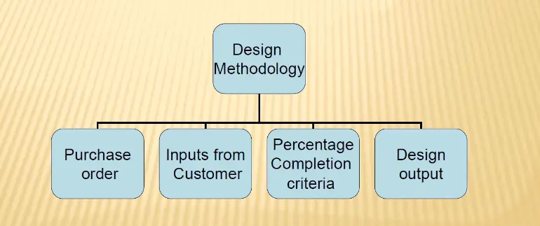
2. What are the inputs required from the customer to start designing a Fixture ?
1. Functional requirement
- Welding fixture
- Hemming fixture
- Checking fixture
- Storage racks
2. Perferred standard components
- Standards like ABB, NAAMS, DESTACO, ZYTRAN, TUNKERS
- Standards parts like risers, L-block, Retainers, Pins
- Components like Clamps, Cylinders, Slides, Switches, Sensors
3. Car product
- GD&T
- part list
- Cad files of car part
- Clamp plan
- Product assembly Process sheet
4. Layout
Layouts provides Information of
- Flow of parts
- Station pitch
- Robot station
- Accessories like tool changer & tip dresser
- Sub assembly link
- Platform height
- Loading / Unloading Sequence height
5. Ergo data
Ergonomics refers to the study of human behavior & movement. Ergo data provides informations of loading height, Working safety zones of operator etc.,
6. Weld study
- Weld gun details
- Weld matrix & Weld points
7. Standard detailing templates
Detailing is 2D representation of 3D part. Customer has standard detailing template. These detailing formats are used for drafting of part.
3. What is the input we get from "Car Products"?
1. GD&T
GD&T provides information of
- Locating pins, Rest, Clamps, Dumps & Slide information of each station
- Sequences of opening of clamps, dumps & slide stoke information
2. Part list
It provides information of
- Part number
- Part name
- Feed design reference
- Support plan
- Part thickness
3. Cad files of car part
Customer must provide a 3D file of that automotive product. The customer provides the 3D model file for the automotive part to be studied
4. Clamp plan
Clamp plan provides the Location of pins, Rests, Clamps, Dumps, etc.,
5. Product assembly Process sheet
4. What is the Clamp plan?
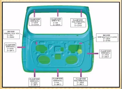
Clamps are a device or component that is used to securely hold or clamp a job in a fixture. Clamps can be manual, hydraulic, or pneumatic, depending on the needs of the customer. The location of clamps in which the component will clamp is mentioned or given in the C lamp plan. We can't move the clamp location without the permission of the customer, so we must first obtain permission from the customer. Clamp plans also show where the pins, rest, clamps, and dumps are located.
5. What is the purpose of a Layout?
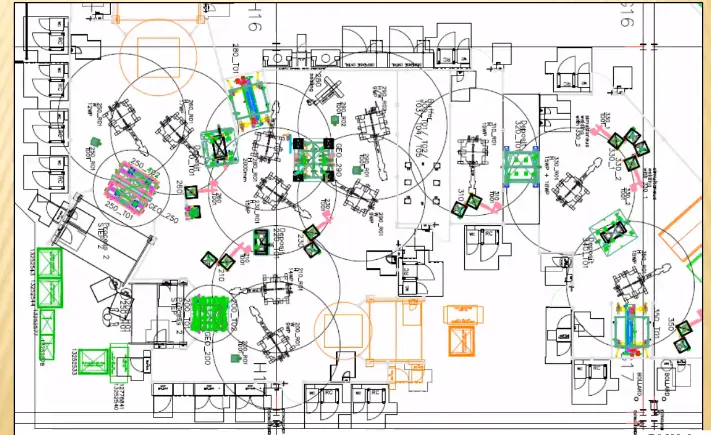
The purpose of the layout is to understand the information about where the fixture & robots are been placed, working area covered by the robot, what are the fixtures assigned for the robots to do the process, etc. layout shows the entire assembly plan to understand the process.
The swept area of the particular robot is shown by the circle surrounding the robot, which indicates the robots' reachability, notably with the confine circle.
Parts flow, station pitch, robot stations, accessories such as tool changers and tip dressers, sub assembly links, plat form height, and loading/unloading sequence/height are all provided by layout.
6. What is Ergo data?
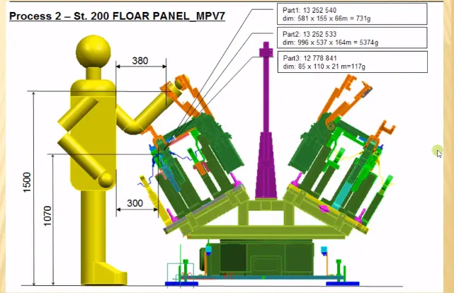
Ergonomics is the study of man and his working environment. Ergonomics strives to provide comfort and better working circumstances in order to channel workers' energy and skills into continuous work. This contributes to better productivity, safety, and fatigue reduction.
Ergo data is provided when a manual operator is involved in an operation, and this information is provided in relation to their ergo data standard. Ergo data includes information such as loading height, working safety, and operator zone, among other things.
The final assembly of an automobile entails a number of difficult jobs. These are the processes that are least likely to be automated. With the help of a modest level of automation, manual labour is best suited for assembly tasks. All processes must be continuously improved in order to minimise costs and increase productivity.
To complete the assembly task, the workers assume various postures, exert force, and work constantly in cycle time. The monotony of working on an assembly line for automobiles is unmistakable.
Ergonomic data is examined in order to discover and quantify ergonomics working postures that contributed to the serious development of muscle skeletal injuries, as well as possible contributory factors. The illustration below depicts an ergonomically suitable sitting position while working.
7. What do you understand by Weld study?
Weld study is one of the most essential customer contributions. It includes information on the type of weld gun we use the number of places to be welded, the welding sequence, and the location of the weld in the components. In a nutshell, a weld study includes information about the weld gun, the weld matrix and the weld spots. Weld points are usually expressed as spheres.
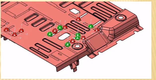
The Geo spot weld points are shown by the red sphere, while the Respot weld locations are represented by the green sphere.
The weld spots are categorised as follows:
- Geo weld points: The Geo weld points are the points in the Geo fixture that are designed. These welds will determine the panel location based on the data in the drawing. In the weld study inputs provided by customers, the geo weld points are represented by a red sphere.
- Respot weld points: The respot tool is used to plan the respot weld spots. The strength/stiffness of the panel/components will be determined by these welds. In the weld research inputs provided by customers, the Respot weld locations are represented as green spheres.
8. What are the criteria for percentage completion in the designing stage? Explain it in detail
In the design and dispatch stages of welding fixtures, the % completion criteria are followed. This percentage completion criteria is used to determine whether the project meets the promised deadline for handing over the projects to the customer.
It also aids us in identifying project stages, such as how much of the project has been finished and what stages need to be completed, allowing us to complete projects on schedule and on budget. To determine the proportion of work completed, the percentage completion criteria are separated into four steps. The following are the four steps of percentage completion criteria:

Input & concept design:
If the project is still in the input and concept design stage, the percentage completion criteria will be between 0 and 25%. After the input and concept design stages are completed, the project will proceed to the concept approval and simulation check stage, which is the second level in the % completion criteria.
Concept approval & simulation check:
If the If the project is in the stage of Input & concept design then the percentage completion criteria of the project will be between 0 – 25%. After the completion of input & concept design then the project will be moved to concept approval & simulation check which is the second stage in percentage completion criteria.
Project is in the concept approval and simulation check stage, the project's percentage completion requirement will be between 25% and 40%. The project will be advanced to design freezing and detailing, which is the third stage in the percentage completion criteria, after concept clearance and simulation check.
Design freezing & Detailing:
If the project is at the design frozen and detailing stage, the project's percentage completion requirements will be between 40% and 85 present. After design freezing and detailing are completed, the project will be moved to check and final dispatch, which is the fourth and last stage in the percentage completion requirement.
Check and final dispatch:
The percentage completion criteria of the project will be between 85 and 100 percent if it is in the stage of check and final dispatch. After the inspection, the project will be successfully shipped to the customer.
9. Brief about "Output" in design?
Many types of data are included in the Design Output, including 3D and 2D documents, VMC IGS files, STEP files, gas-cut or laser-cut files in dwg format, and BOM, among others. These data must be sent to our customer as a design output. 3D models and 2D drawings of the fixture are the primary outputs. The following are the categories of output:
1. Unitised Tool: This tool is made up of two different types of sheets:
key sheet: The location of each unit in the fixture is indicated or shown
Layout Sheet: A layout sheet is a detailed representation of a specific fixture unit.
2. Non Unitised tool: Tools that aren't unitised: These tools don't require a key sheet. Stands and tool changers, for example. Details in the layout sheet and stand-alone tools.
10. What do you understand by structuring a design tree? How does it reduce errors during the design process?
- Structuring a Design tree implies to a process where all the assemblies & parts are named in a specific standard. Different customers have different set of standards to structure a design tree
- It is a improtant process which help us to identify a specific part or assembly, as to which project, tool or unit, it belongs to.
- This help us to avoid the error during design study, manufacturing, assembly, inspection, etc.
- If the part or assemblies are not named properly or the design tree is not structured properly, it will create confusion to understand the design & may create major possibilities of making an error.
- Naming of the fixtures or a unit or a part, gives the information as to which project or zone or assembly do they belong
11. What are Units? Mention 5 types of units.
Unit is a device that performs a certain job, usually as part of a larger mechanism. A welding fixture is an assembly of various elements. The varied units will only be shown in the unitized tool, as the name implies. A unit is divided into two categories:
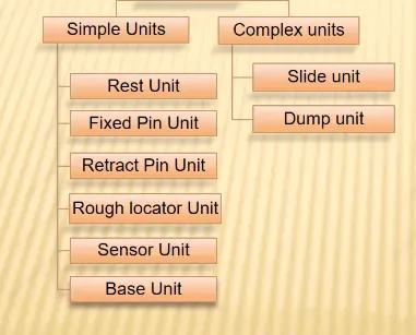
12. Describe Fixed Pin units & their purpose?
A fixed pin unit is a device that uses pins to locate a car panel. The unit pin is already fixed and cannot be moved, and the following are various parts of the unit in general. Pin, pin retainer, shims/ spacers, block, blade, or adaptor plate is the main components of a fixed pin unit. That pin is held in place by a pin retainer.
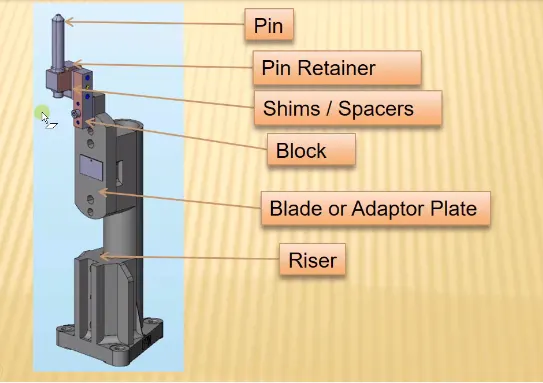
Purpose of fixed pin unit
The installation of two pins helps to arrest the 6 degrees of freedom (4 axial & 2 radial motions) according to the 3-2-1 locating principle, whereas the remaining 6 degrees of freedom are arrested by introducing at least three supports. Typically, locating pins are used to locate a body part in a location that is exact enough to carry out a welding procedure. A series of correctly locating pins constrains the body part; therefore complete constraint by locating pin should be entirely limited at all times to prevent any movement.
13. What are the different parts of a fixed unit?
1. Pin
The panel's placement is determined by this pin. Standard pins should be utilised as much as feasible, and pin lengths should be kept to a minimum. Pin diameters should be cylindrically ground to keep their dimensions correct. Two locating pins are usually sufficient to accurately position the work item on one plane. Locating pins come in a variety of styles that can be used in a design. We'll go over the structure and demonstrate how each style can be used.
2.Pin retainer
This pin is supported by a pin retainer. The Pin Retainer is utilised to keep the pin in place while also acting as a rest for the pin. A counter hole is drilled into which the pin will be inserted.
3.Shims/spacers
Tolerance is provided in the fixture for each part that is largely fabricated. Those tolerances tend to accumulate and reflect one another. To avoid this, we utilise shims, which we can simply change after assembly, so whatever stacks up there will be corrected with shims. Shims are available in various thicknesses, such as 0.1, 0.2, and 0.5.
4.L-Blocks
The L-Block is only used to provide shimming for adjustment. We should check bolting access while installing an L block because there is already a bolt to tighten the pin. As a result, the L block should provide a clear hole.
5.Blades
Blades are plates that are fastened to the riser. Other components, such as the cylinder and arms, are mounted to the blade. The purpose of the chamfer is to reinforce the blade. To secure the blade to the riser, a two-dowel four-hole configuration is used.
6.Risers
Risers might be L-shaped, welded, square tube, or frame-shaped. These are manufactured pieces that are utilised to give assembly height.
14. What is the purpose of making a Rest unit & describe its parts?
A rest unit is a support unit for a car panel made of Mylar/NC block/rest. There is no upper clamp or force applied to the component; it is just resting. Because there are fewer pieces to build and the goal is merely to rest the car panel, it is the simplest unit to design.
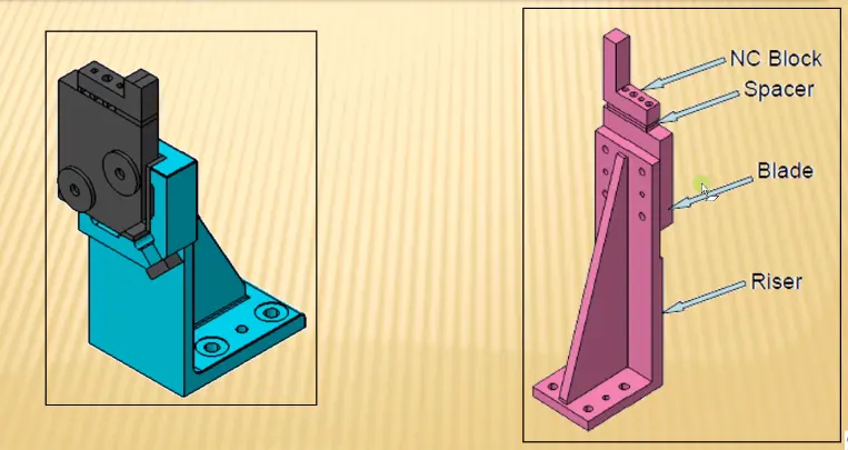
1. NC blocks
These are the elements that hold the panel together. They're known as Mylar over the world. Clamping Mylar is on the top side, and resting Mylar is on the bottom. There should be resting Mylar for every clamping Mylar. It is of the jaw kind. It prevents the panel from deforming during the welding process. It has been toughened to boost its wear resistance.
2.Shims/spacers
We provide tolerance to each part that is mostly manufactured in the fixture. These tolerances tend to accumulate and reflect one another. To avoid this, we employ shims, which allow us to simply adjust after assembly, so anything stacks up there will be corrected using shims. Shims are available in various thicknesses such as 0.1, 0.2, and 0.5.
3.Blades
Plates positioned on the riser are known as the blade. Other components, such as the cylinder and arms, are mounted to the blade.
4.Risers
Risers might be L-shaped, welded, square tube, or frame-style. These are manufactured pieces that are utilised to give assembly height. It is merely machined at the mounted ends to save money.
15. What are the basic fundamentals to design a Sensor unit?
An electrical sensor is used to sense the automobile panel. The sensor's signal will be transmitted to the PLC, and the next procedure will begin. Sensor units are used to detect if a panel is present or not, or whether a certain component is present. If 9 pars are required for assembly, we must have at least that number of sensors. When an operator manually assembles a complete component, they perform tasks such as fastening and gluing. If a component is present, the sensor will indicate it, and if it is not, an error will be displayed.
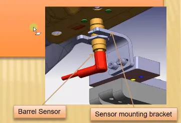
Types of sensor used in general.
Proximity sensor - It has sensing range 5 to 6 mm. It is based on magnetic field principle. A proximity sensor is a sensor able to detect the presence of nearby objects without any physical contact. A proximity sensor often emits an electromagnetic field or a beam of electromagnetic radiation (infrared, for instance), and looks for changes in the field or return signal
Laser sensor: It has a longer detection range than a proximity sensor. A photoelectric sensor is a piece of equipment that uses a light transmitter, usually infrared, and a photoelectric receiver to determine the distance, absence, or presence of an object. They're commonly found in industrial settings. As shown in the diagram below.
16. What is a Rough locator unit & what are the basic fundamentals to consider while designing it?
Rough locators are typically employed in the loading and unloading of certain parts. It can also be used as a guide. The rough locator unit is meant to assist the operator in correctly locating the car panel on the pins. They have an adjustable slot. A standard component or mate part can be used to make a rough locator. It can also be used as a pokayoke.
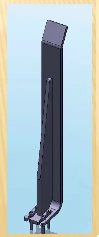
Rough locator design fundamentals:
- Rough locators should be positioned at the edge of the car panel that has to be guided. By using locating pins, the entire car panel may be readily restricted.
- Rough locator must be set at the same angle as the car part edge and at least 2.5 mm away from the edge of the car component to avoid damaging the panel.
- Before 10 to 15 mm from the start of the pin engagement, rough locators should be used to guide the panel.
- In general, rough locators should lead the panel in a pin arresting direction.
- Rough locators should have two mounting slots for ease of adjustment.
- The slot should face the car panel guiding direction.
17. What is a Base unit and describe it's parts?
A base unit is the unit that is used to mount the entire tool's other units (clamp, pin, and rest units), as well as any additional parts that are required.For a tool like a pneumatic valve box, the trucking cable path will also be installed on the base unit, and the parts listed below are some of the base unit's general components.
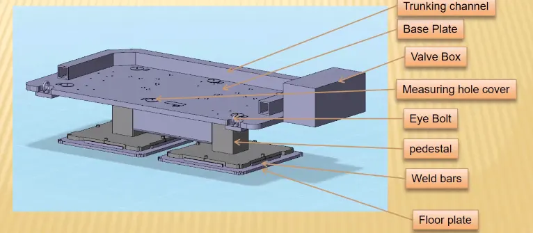
1. Base Plate
A base plate is a machined steel or aluminium plate with a thickness of 25mm to 40mm on which holes are drilled to mount various units such as rest units, clamp units, pin units, and so on.
2.Pedestal
Pedestal is a portion or assembly (welded construction) that connects the base plate to the floor plate. Depending on the size and height of the fixture, the pedestal can be a standard or custom element. Standard pedestals come in a variety of heights. Different inclinations of pedestals are also available. The number of pedestals for a fixture might vary depending on the size of the base plate for load distribution.
3.Valve box
valve box has a solenoid valve that feeds air to pneumatic cylinders and coils. A group of valves is sometimes referred to as a valve blank.
4. Trunking channel
A base-mounted trunking channel is utilised to direct all electrical cable and pneumatic pipe. The entire fixture unit is supported by the base. Trunking Channel is a duct that transports all of the tool's electrical and pneumatic connections (wires and pipes). It is only a few millimetres thick.
5. Eye bolts
These are used to elevate the complete base unit, as well as the pedestal and the base plate.
6. Floor plate
They are used to install the complete unit, and a levelling arrangement is provided to the base unit, such as a levelling bolt and pad, to level the entire unit.
18. What is a Dump Unit and what are its functions?
If you have a time limitation, you can assemble components in a dump unit. Clamp and pin units will be attached here, and the panel will be constructed. As a result, if you have a certain limitation, you won't be able to build normally.
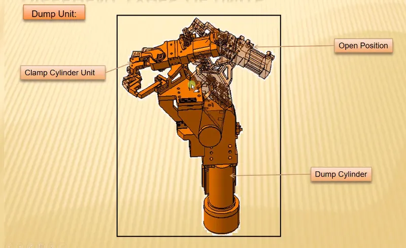
Dump units are used in a variety of ways. It features a dump cylinder and a complicated construction. It has a dump cylinder that performs the clamping and unclamping of automobile panels. To conduct such an activity, a dump unit can have many cylinders. The first cylinder deposits the clamp milers and pins assembly, which then conducts the essential operation. In this unit, we need ensure that we can remove the panel when it is in the open position.
19. What is a Slide unit? Mention where Slide units are commonly used.
The sliding unit is made up of sliding cylinders. It moves back and forth between open and closed positions. It features a shock absorber at the end and a hard stopper beyond that. It comes with a guiding rail. It makes use of a sliding mechanism. It also features a position locking device for maintenance purposes, which prevents the entire unit from being moved, as well as a sensor unit to detect whether or not the full component has been reached on either side, or a stopper block to control movement. When the cylinder opens, the panel is unlocked by the position locking mechanism. Using a frictionless guide block, the entire panel is then moved to the open position. The guide block must be greased on a regular basis.
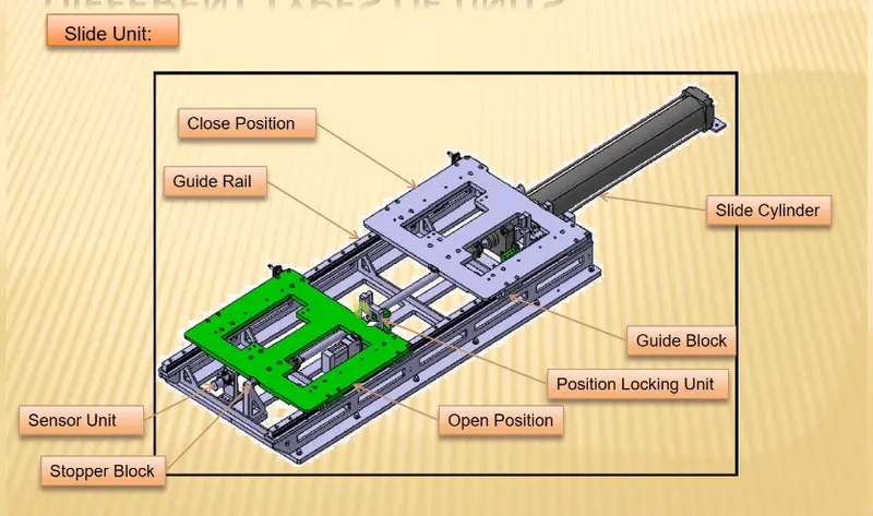
Sliding units are typically used in areas where there is a limited amount of space. There are sometimes too many little panels close together, and there isn't enough room because each panel requires resting, two-pin placement, clamping, and sensing. When the panel is at an angle, this becomes even more challenging. To tackle this difficulty, a slide unit uses guide rails, guide blocks, a cylinder, locking mechanism, stop blocks, and sensors to attach a rest, clamp, or pin unit, or all of them, on a slide. When a certain panel needs to be welded, this slide slides forward, fixes the panel, and then returns to its original place after the process is completed. Similarly, other panels are treated in the same way.