Week 3:- BiW Fixture Design Methodologies Challenges
#1_Design Methodology: It is a sequence or steps followed during the concept designing stages of Fixture Design.
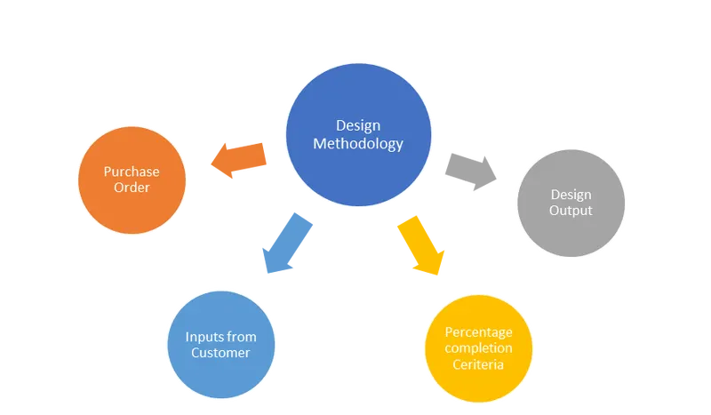
Purchase Order: A purchase order (PO) is a commercial document and first official offer issued by a buyer to a seller, indicating types, quantities, and agreed prices for products or services.
Inputs from Customer : We have to consider, Functional Requirements, Standard components, Ergo Data, Detailing Templates,etc as Inputs from the customer end.
Percentage Completion Criteria: This Criteria if followed in the Designing Stages and Dispatch Stages of the welding fixtures.
- 0-25% - Input & concept Design
- 25-40% - Concept Approval & Simulation Check
- 40-85% - Design Freezing And Detailing
- 85-100%- CHeck & Final Dispatch
Design Output: A design output is a drawing or specification or manufacturing instruction. Design outputs describe all the components, parts, and pieces of the assembly.Design outputs describe all assemblies and subassemblies of your product.
#2_Inputs Required from Customer to initiate fixture design are as follows:
- Functional Requirements: The function of that particular fixture design.
- Preffered Standard Components: Existing components which the customer already has can be used as Standard component like,cylinders, switches, Retainers, pins.
- Car products: It includes GD&T, CAD files,Part list, Clamp plan,Assembly process sheet.
- Layout: Layout basically gives an idea about the position of fixtures and swept area of robots.It provides information about the Flow of parts, station pitch, Robot stations, Tool changer, tip dressers, Sub Assembly links, Platform height, Loading or Unloading Sequences.
- Ergo Data: It provides info. of loading heights, working safety zone of worker, etc
- Weld Study: It includes Weld gun details, weld matrix and points.
- Standard Detailing Templates.
#3_Inputs we get from Car Products:
- GD&T: Geometric Dimensioning and Tolerancing (GD&T) is a system for defining and communicating engineering tolerances and relationships.
- CAD files of Car Parts
- Part lists:
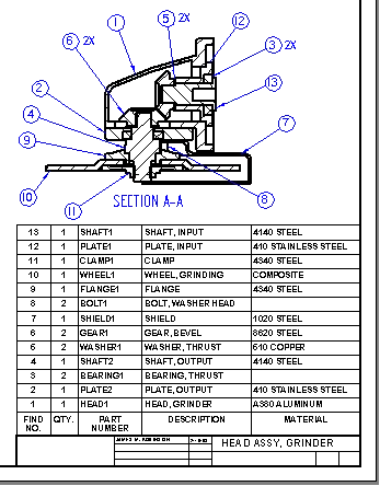
It is a tabular list of the items used to make an assembly. Parts list is usually combined with the assembly drawing, but it is a separate and individual document and can be and provides a complete list of all parts needed to build the complete project.
- Clamp plan: It gives the idea about the locations of pins, Clamp and Rest Units.
- Assembly process sheet: A process sheet is a set of manufacturing instructions for a specific batch, lot, or run. It describes the operating parameters and settings for the equipment and facilities used and associated tooling or supplies.
#4_Clamp Plan:
Clamp plan provides us information about the location of Pins, Rest UNits, Clamp Units,etc by using proper co-ordinates. It is one of the inputs we consider from customer's end.
#5_Purpose Of Layout:
Layout basically gives an idea about the position of fixtures and swept area of robots.It provides information about the Flow of parts, station pitch, Robot stations, Tool changer, tip dressers, Sub Assembly links, Platform height, Loading or Unloading Sequences.
#6_Ergo Data:
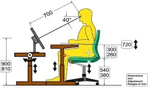
Ergonomics (or human factors) is the scientific discipline concerned with the understanding of the interactions among human and other elements of a system, and the profession that applies theory, principles, data and methods to design in order to optimize human well-being and overall system performance.
Ergo Data provides information of loading heights, working safety zone of worker, The angle of tilt, etc.
#7_Weld Study:
Weld Study includes information about Weld gun details, weld matrix and points.
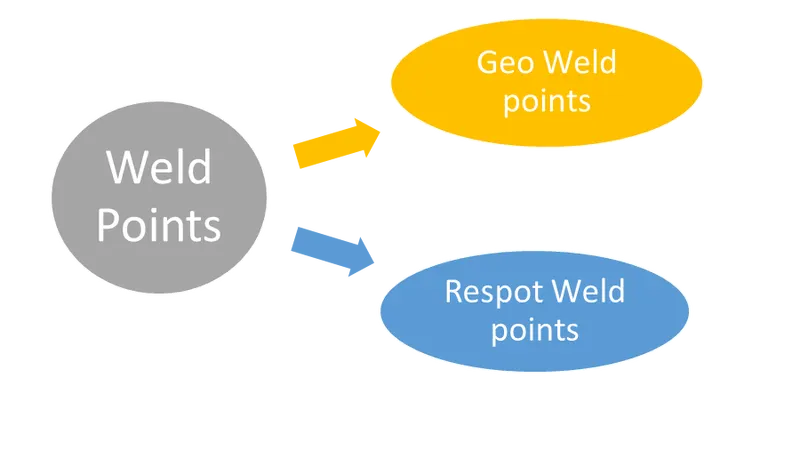
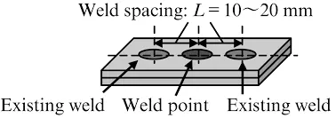
Geo(Red)- It defines geometry of part.
Respot(Green)- All the remaining weld points and strethens the geo weld points.
#8_Percentage Completion Criteria:
This Criteria if followed in the Designing Stages and Dispatch Stages of the welding fixtures.
- 0-25% - Input & concept Design
- 25-40% - Concept Approval & Simulation Check
- 40-85% - Design Freezing And Detailing
- 85-100%- Check & Final Dispatch.
#9_Design Output:
A design output is a 2D or 3D drawings or specifications or manufacturing instruction given to the customer after design stage.. Design outputs describe all the components, parts in an assembly. Design outputs describe all assemblies and subassemblies of your product. In order to adequately evaluate design outputs, design verification is necessary. And this evaluation is comparing design outputs against design inputs.
#10_Structured Design Tree:
As our CAD designs/projects develop, our design tree will inevitably become more complicated and more difficult to navigate and interpret. This issue becomes more significant if geometry requires modification or when it is handed off from one designer to another.
- Having our tree organized/Structured in a logical manner will allow users to probe their model and navigate to specific objects more efficiently.
- If the part file is not named properly, it might create confusion for the another person and end up throwing errors.
- It helps us avoid the errors during design study, manufacturing,inspection,etc.
#11_Units and its Types:
Unit is a device which has a specified function.A welding fixture is a assembly of Different units.
There are Following types of units:
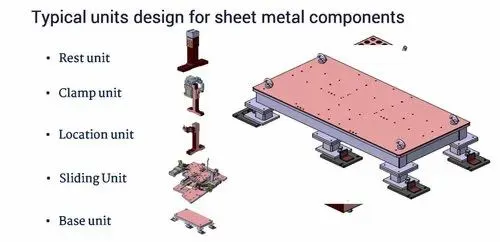
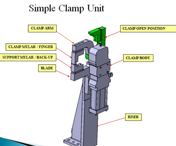
Clamp unit: A clamp unit is a unit designed to clamp/hold the car panel with NC blocks/Mylars/rest by using a pneumatic cylinder.
Fixed Pin unit : Fixed pin is a unit designed to locate the car using pin. As the name suggest it uses a fixed pin which cannot be moved by any distance.
Retractable Pin Unit: A retractable pin unit is a unit designed to locate the car panel using pins, but the entire pin package parts will be mounted on the retractable pneumatic cylinder.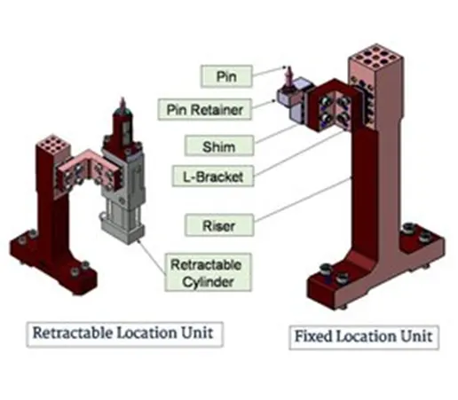
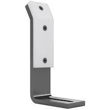
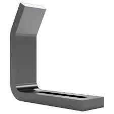
Rough Locator Unit: The rough locators are set according to the angle of the respective panel hence part can only be loaded in defined direction & orientation.
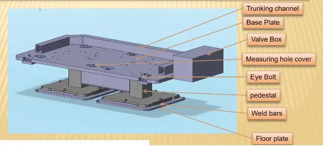
Base unit: A base unit is the unit designed to mount all the other units(Clamp unit, Pin unit, rest unit etc.)
#12_Fixed Pin Unit & Its Purpose:
Fixed pin is a unit designed to locate the car using pin. As the name suggest it uses a fixed pin which cannot be moved by any distance.
Its primary function is to restrict the workpiece's degree of freedom, Rotational or translational motion.
#13_Different parts of Fixed pin unit:
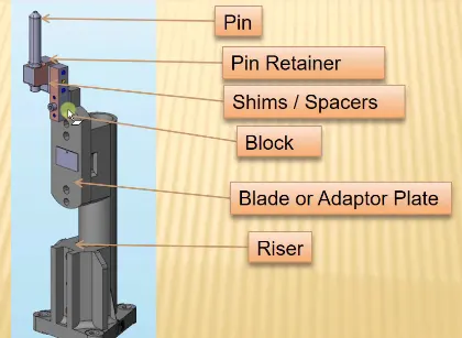
Pin: It is used for Locating coordinates on the panel of component.
Pin Retainer: It is precision fasteners used to prevent a wheel or other part from sliding off the axle upon which it is riding.
Shims: A shim is a thin and often tapered or wedged piece of material, used to fill small gaps or spaces between objects.
Blade/Adaptor Plate:The plate which connects Riser to the Clamp cylinder is named Blade. This plate plays an important role in building the unit. The plate can be of any shape. But we need to keep in mind that the plate should be as compact as possible.
Riser: The part which is mounted on the base plate and holds a clamp or pin cylinder on it, is called Riser.
#14_REst Unit: It is designed to support the car panel using Mylars or NC Blocks.
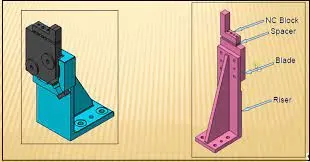
NC Block: It is one kind of block that touches the panel and holds or clamps the panel.
Spacer: A Spacer is a thin and often tapered or wedged piece of material, used to fill small gaps or spaces between objects.
Blade: The plate which connects Riser to the Clamp cylinder is named Blade.
Riser: The part which is mounted on the base plate and holds a clamp or pin cylinder on it, is called Riser.
#15_Basic Fundamentals to design sensor unit:
- Every single loose panel which are being welded in tool should be sensed.
- Each panel Should be sensed 1 or 2 sensors depending on the siize of panel, preferred to be in diagonal opposite ends of panel.
- Every sensor shoould be mounted in all 3 direction adjustable way in general.
#16_Rough Locator Unit and Basic fundamentals todesign it:
The rough locators are set according to the angle of the respective panel hence part can only be loaded in defined direction & orientation.
Fundamentals:
- Rough locators should be placed at the car panel,which it has to guide.
- Rough locators should be placed in the same angleof the part edge with a min. distance of 2-5mm from the edge of car panel.
- Rough locators should guide in the pin arresting direction.
- Rough locators should start guiding the panel before 10-15mm to the satrt of pin engagement.
- Rough locators should be designed with entry anglefor car part entry.
- Rough locators should be designed with two slots to mount for easy adjustments.
- The slot should be in the direction of car part guiding.
#17_Base Unit:
A base unit is the unit designed to mount all the other units(Clamp unit, Pin unit, rest unit etc.)
It consists of different parts like, Base plate,Weld bars, Valve box, EyeBolt, etc.
#18_Dump Units:
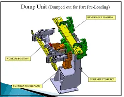
Dump unit is the complex unit to design due to space constains there is less space avilable & have to adjust all the parts in available space. It consist of dump cylinder to perform the operation of clamping & unclamping car panel.
.
Functions of Dump Unit:
- To ensure there are is no rotation in the panel and to fix it either by pins or side blocks or magnets.
- To ensure there is enough clamping force in the cylinder so that it doesn't move while welding.
#19_Slide Unit:
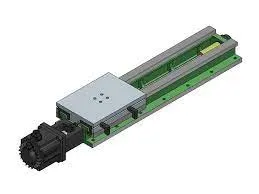
Slide unit is found mostly in complex fixture, where the sliding mechanism will be involved.
This type of unit used when there is some space constraints. Guide block, guide rail, position lock unit, stopper block, sensors are the parts of slide unit in general.