Week 3 - 2D meshing for Sheet metal
Week 3 - 2D meshing for Sheet metal
Question
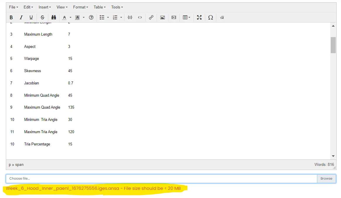
For the given Hood model, Take the mid surface after checking the geometrical errors and mesh the mid surface with the given element Quality criteria. (Refer to the table below for the Quality criteria)
|
S.No |
Quality Criteria |
Value |
|
1 |
Target/Average length |
5 |
|
2 |
Minimum Length |
2 |
|
3 |
Maximum Length |
7 |
|
4 |
Aspect |
3 |
|
5 |
Warpage |
15 |
|
6 |
Skewness |
45 |
|
7 |
Jacobian |
0.7 |
|
8 |
Minimum Quad Angle |
45 |
|
9 |
Maximum Quad Angle |
135 |
|
10 |
Minimum Tria Angle |
30 |
|
11 |
Maximum Tria Angle |
120 |
|
10 |
Tria Percentage |
15 |
Note: All the 2D elements in your model should clear the above-mentioned quality criteria and the features in the model have to be captured properly with good mesh flow. Depending upon this you will be awarded marks.
Note: After meshing the Mid-surface, Thickness must be assigned to the Mid-surface.
Steps to Take:
-
Import Model
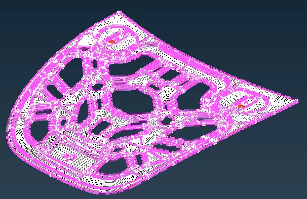
Launch ANSA and open the given file. The hood model that is provided is divided into three parts:
Surface Extract
Hinge
A consistent thickness latch
-
Geometry Clean-up:
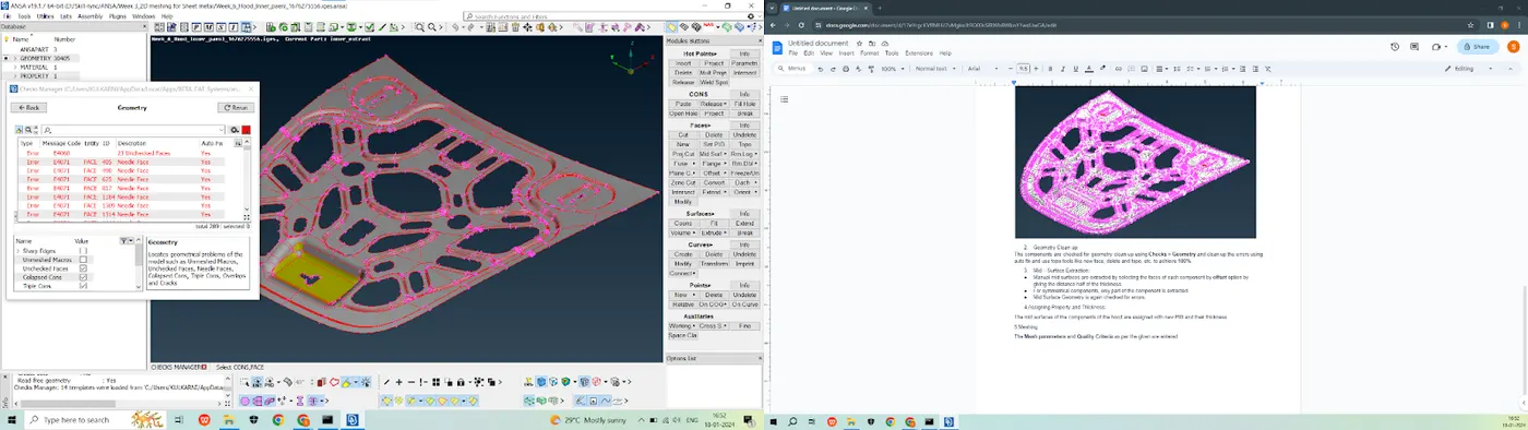
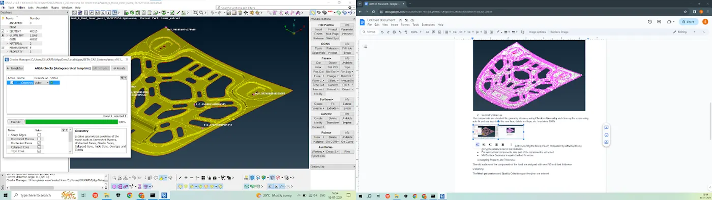
In order to attain 100%, the components are checked for geometry clean-up using Checks > Geometry, and any errors are automatically fixed using auto fix and topo tools like new face, delete, and topo, among others can be used to fix the errors manually and as seen in the image below, by going to Checks>Geometry and running it for parameters. An additional image displays the errors found.
-
Mid – Surface Extraction:
-
By choosing each component's face using the offset option and providing the distance as half of the thickness, manual mid surfaces are extracted.
-
Merely a portion of the component is extracted for symmetrical components.
-
Mid Surface Geometry is once more examined for mistakes.
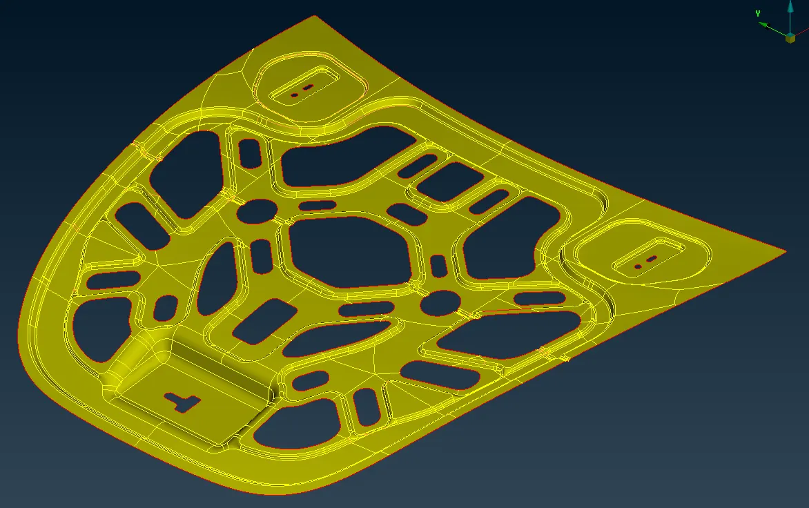
Below is a display of the final extracted mid surfaces.
4. Assigning Property and Thickness:
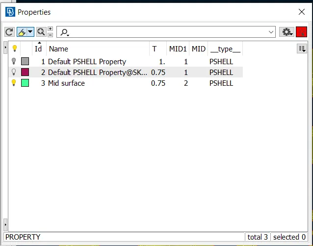
The new PID and thickness of the hood's component midsurfaces are assigned.
By selecting Faces>Set PID and assigning to the appropriate property, the property is now assigned to the extracted mid surface. In a similar manner, every component's midsurface is extracted and given a property.
5. Meshing
The Mesh parameters and Quality Criteria as per the given are entered.
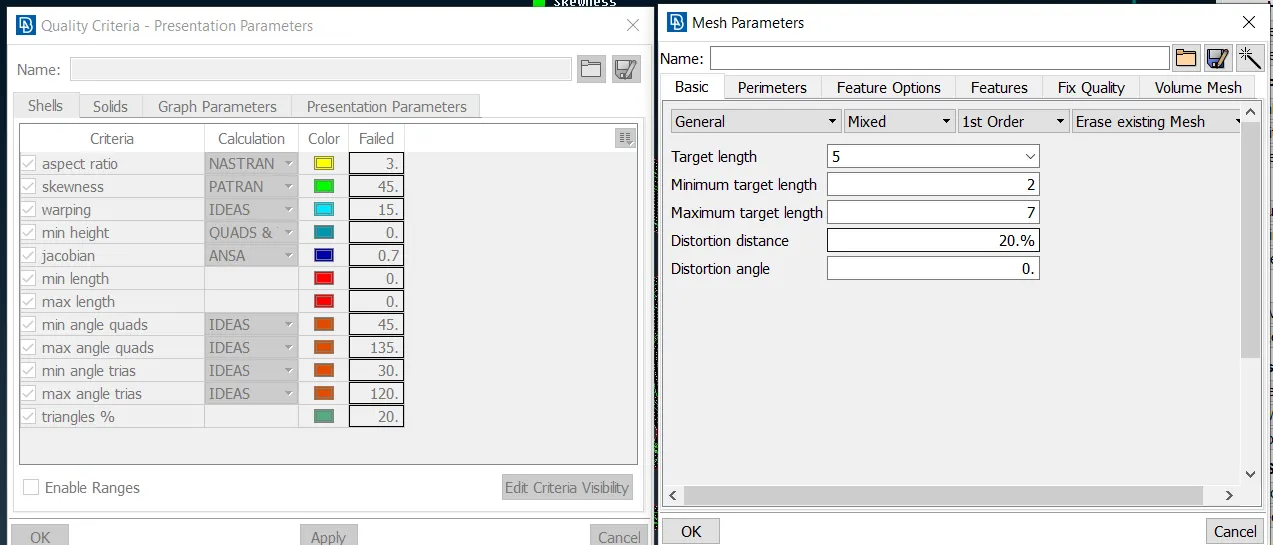
Next, mesh parameters are configured by going to Utilities>Mesh Parameters. There, target length, minimum element length, and maximum element length are configured to 5, 2, & 7, respectively. All other parameters are kept as default for mixed and 1st order elements.
Next, quality criteria are configured by going to Utilities>Quality Criteria. And, the quality criteria file is saved for future reference. The created quality criteria parameters are shown in the image below.
-
The mid surfaces must then be ready for meshing. Use the Mesh module for that.
-
To change the length of the shell element, go to Perimeters>Length, select all CONS, and enter 5 as the target element's length.
-
For every Macró (surface), the same procedure is followed.
-
Subsequently, the minimum element length is verified for each area and any areas where elements might not meet the minimum length are changed.
-
In a similar vein, CONS that are not required to define a feature are eliminated by using the Macros>Join tool to join the surfaces.
-
Additionally, the Macros>Cut and Macros>Project Cut tools are used to strategically divide the entire mid-surface model into sections. This will contribute to producing a mesh of higher quality.
-
In order to make sure the CONS are parallel to the surrounding CON, all of the holes are also rotated using the Perimeters>Slide tool.
-
This will assist in creating a mesh that flows well.
-
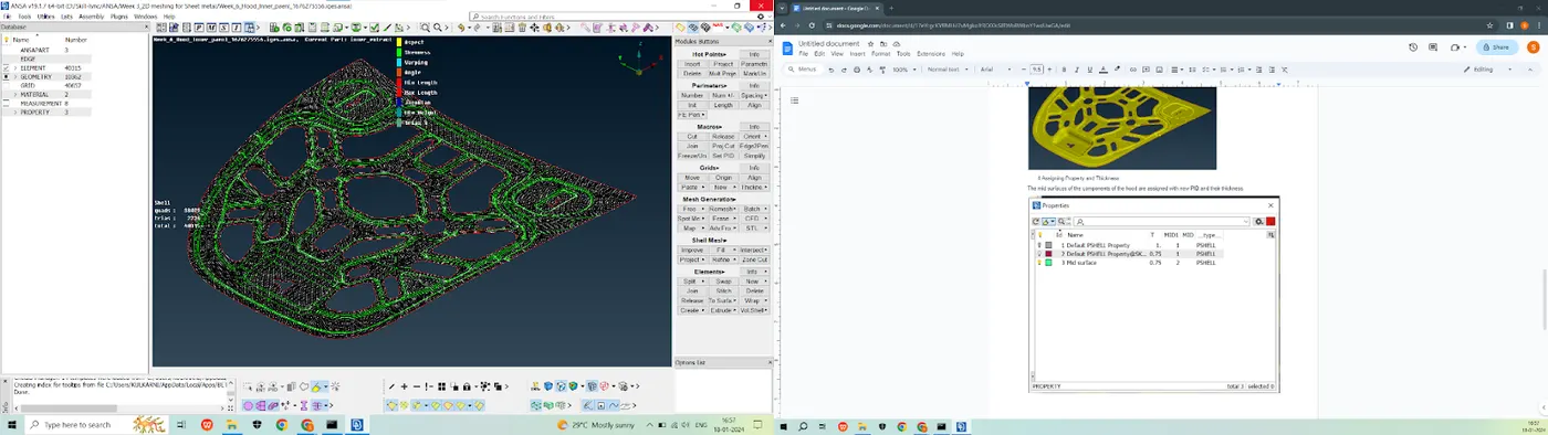
The image below displays the outcome of the previously mentioned steps. For each of the mid-surface components, the same procedure is repeated.
Afterwards, the Mesh generation>Best tool is used for meshing. This tool uses the most appropriate algorithm to generate the mesh. The Shell Mesh>Reconstruct tool is then used to fine-tune the created mesh. It is made sure that none of the quads are rotating. Trias are also kept to a minimum. The following must be made sure of when working with trias.
The following resources are utilized to address trias:
Grid>Paste to move tria backward and paste the nodes
Elements>Split: To divide an element and advance three
To move the tria left or right, select Elements > Swap.
Parts>To create a quadruple, join two trias together.
The mesh is modified, and then the mesh flow is smoothed using the Shell Mesh>Smooth tool. Remeshing or smoothing the elements fixes any parts that don't meet the quality standards.
In summary:
The provided hood model's geometry cleanup, mid-surface extraction, and 2D meshing were completed successfully. Additionally, every component meets the quality standards. Every feature in the model is accurately represented with a well-organized mesh. Low tria concentration is maintained.
Not able to upload the CAD and ANSA file due to high size