Week 3 - 2D meshing for sheet metal
Aim:- Extract the mid surface for given Sheetmetal component and mesh the component, assign the quality criteria as per given parameters.
S.No Parameters value
- Target/Average length 5
- Minimum length 2
- Maximum length 7
- Aspect ratio 3
- Warpage 15
- Skewness 45
- Jacobian 0.7
- Minimum Quad angle 45
- Maximum Quad angle 135
- Minimum tria percentage 30
- Maximum tria percentage 120
- Tria percentage 15
Procedure: -
- Import the model into ANSA GUI interface. The model consists four components, proceed with one by one by hiding the components in tools > properties manager.
- Check the geometry connectivity, fix the topology with topo function in the face’s module.
Topo module -->Faces>Topo
- Using the geometry checks in the checks manger, fix the topology errors like triple cons, called cons which sharing three surfaces and also single cons, gaps between faces.
- Then, do a cons resolution using the length option in the perimeters module, assign the value 1 for resolution.
- Manually extract the mid surface after topology clean-up using an option Topo> Faces>offset , sometimes extraction of middle surface can be done automatically by an option used Faces>middle surface>skin.
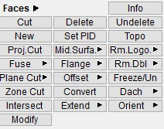
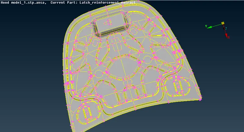
Fig1 Hood component
After extracting the mid surface:-
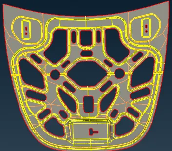
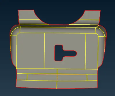
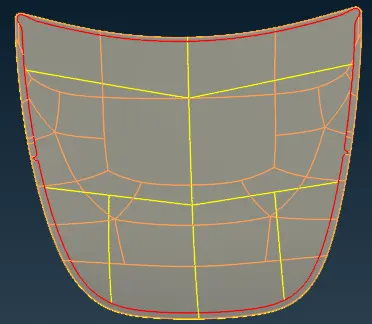
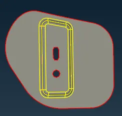
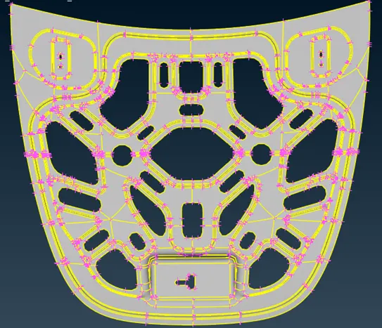
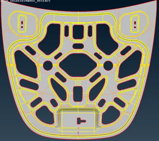
Before cleanup After cleanup
Few cons restricts the mesh flow while meshing, for a smooth mesh flow convert the unneeded edges/cons into joined cons,using a cut option.
Topo-->Faces>cut
- Observe the component, use the advantage of symmetry cut the model and work on the model topology.
- After cleaning the topology, assign the quality parameters.
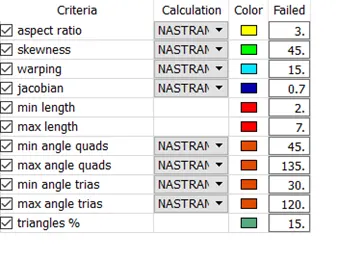
Quality parameters
- Divide the cons as per average element length for meshing, assign the value 5 using the length option.
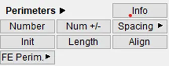
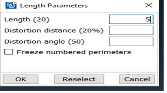
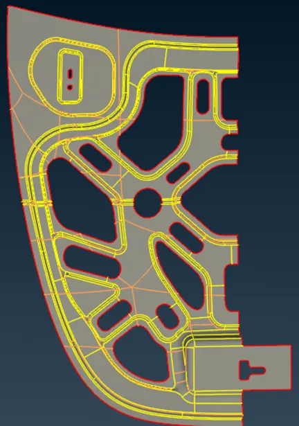
Fig3 After symmetrical cut
Do work on half portion, after then meshing copy the elements using transform option.
Utilities>transform> copy
- Assign the mesh parameters as per shown.
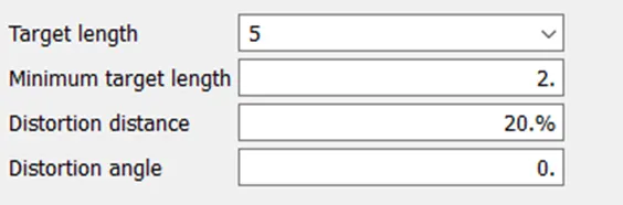
Meshing parameters
- Mesh the component using options best, batch, free, which are available in the mesh module> mesh generation.
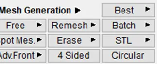
- Start meshing from one side of region and mesh the model. while meshing few elements are deviated from the quality criteria, to fix the elements use manual operations like
Splitting the elements--> Mesh module>elements>split
Paste the nodes towards the edges --> Mesh module>grids> paste
- Remove trias like opposite trias, trias grouped, tria along edges, trias on fillets by using above commands.
- To get the better mesh flow reconstruct the mesh, reshaping and smoothing the meshing using an option reconstruct, reshape, smooth.
Mesh module>shell mesh> Improve
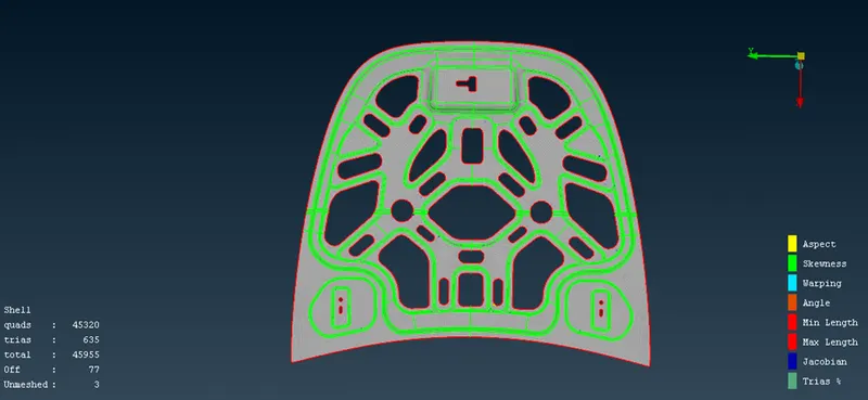
Fig4: After meshing the outer panel
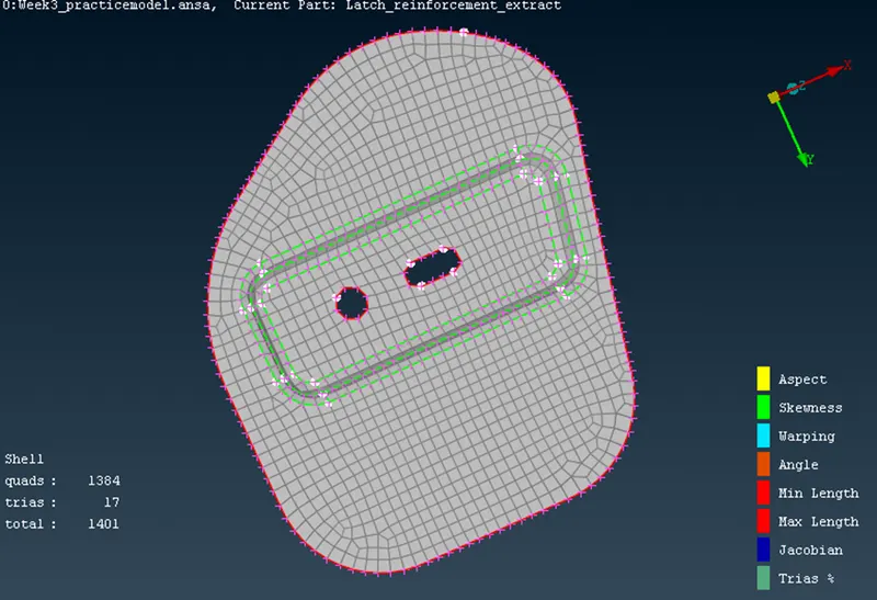
Fig4 latch
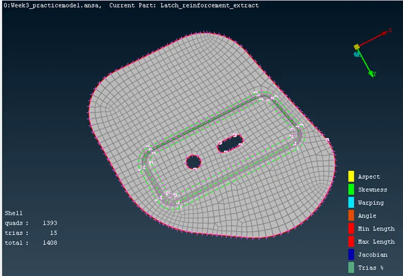
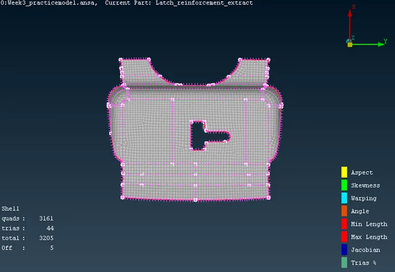
Fig5 Hing
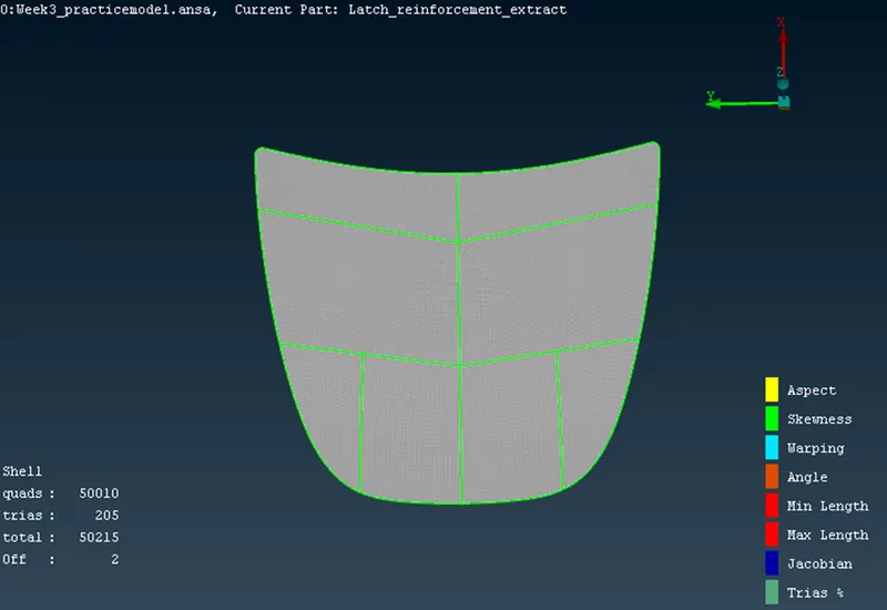
Fig6 outer panel
convert 2d shells to solid elements by mark an option--> draw shell as solid.
utilities--> quality criteria> presentation parameters.
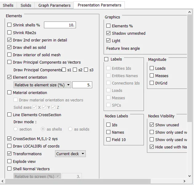
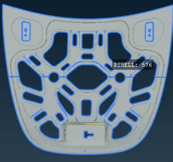
2d to solid elements
Conclusion: -
The component has been meshed as per given quality parameters, converted 2d shells to solids by following the techniques metioned in the procedure.