Week 3 - 2D meshing for sheet metal
AIM: To extract the midsurface for the given model and mesh it with the proper mesh flow with lower trias elements.
Objective:
i) Develop a 2D mesh for the Hood model.
ii) All the elements in the model should clear the below-mentioned quality criteria and the features in the model have to be appropriately captured with good mesh flow.
iii) After meshing the Mid-surface, after that assign the thickness must be assigned to the midsurface to it.
Theory:
ANSA is a computer-aided engineering tool for Finite Element Analysis and CFD Analysis widely used in the automotive industry. It is developed by BETA CAE Systems.
ANSA is an advanced multidisciplinary CAE pre-processing tool that provides all the necessary functionality for full-model build-up, from CAD data to ready-to-run solver input file, in a single integrated environment.
ANSA is the users’ preference due to its wide range of features and tools that meet their needs. The list of productive and versatile features is long and the alternative tasks and processes to be completed using them are countless.
Benefits:
Efficient data handling for intricate model structures
Fast and high-quality modeling of complex geometries
Capability to interoperate between models built for different solvers
Highly automated processes and model set-up tools in one environment
Reduced user-dependent error-prone operations
Complete model build-up for numerous solvers in one environment
Unique capability for building a common model as a basis for modeling for different disciplines
Significant modeling time reduction and quality increases.
Color Representation in ANSA:
RED: It represents Single free edges Cons.
YELLOW: It represents Double Cons in which 2 edges are been shared.
CYAN: It represents Triples Cons in which 3 or more faces have been shared together.
You can activate and deactivate the visibility of each of the 3 types of CONS separately using the SINGLE, DOUBLE, and TRIPLE flag buttons.
De-activating here the DOUBLE flag shows only the free red and triple cyan CONS. Apart from the free edges of the sheet metal, there are other openings (gaps, untrimmed Faces, etc.) that must be corrected.
Procedure:
Import the CAD model to the ANSA profile.
Read the file to perform the topology option using the TOPO option available in FACES.
Perform the geometry cleanup and check the geometry error in it.
Measure the thickness of the component with the different thicknesses present in it.
Extract the Midsurface using Auto-midsurface and for the outer extract part, I have used the offset method.
Perform the mesh for the extracted midsurface with the separate surface to get good mesh flow in it.
Once creating the mesh in it, we can check with the quality check for the meshed element
Assign the parameter and resolve the error with different tools.
Topology and Geometry Cleanup:
Importing CAD: Import the model in ".step" or ".iges" format to the ANSA software.
Once checking the model we have to check it for errors in it.
An error such as orientation issues, duplicate, missing surfaces, sharp edges, Needle edges, etc..,
This topology cleanup is performed on the model using the topo operation in the FACES block of the TOPO module.
To perform geometric checks, Checks - Geometry - Select required params
ANSA can give a layout of all the geometrical errors from our component model.
A target length of 5mm is set for the entire model in both the perimeter and the macro-region.
Perform a topology cleanup using the Faces-> Topo.
Do a geometry check for single, double, and triple cons and eliminate those that may cause geometrical errors by selecting the components and right-click then click Fix.
Picture to be added
Midsurface Extraction:
Mid-surface extraction is usually used for sheet metal components where the thickness of the component is negligible compared to the other two dimensions. Mid-surfaces can be extracted in ANSA either automatically or manually. In certain cases, ANSA may fail to deliver the proper FE model, in the case of auto mid-surface extraction, if the model comprises critical regions with complicated features or most small features. Another reason why an auto mid-surface feature may fail is because of varying thicknesses across the model.
Mid-surface extraction depends on the symmetry and thickness of each respective part in a component. In the case of varying thickness, the auto mid surface (Topo - Faces - Mid surface - skin, casting, etc..) doesn't give a proper result. Hence manual mid-surface extraction using the offset and manual mid features can be implemented.
The offset command (Topo - Faces - Offset) can be used for known thickness features in the component where discontinuity occurs due to other mid features present. Whereas the single/multi-middle feature (Topo - Faces - Middle) can be used for features that are symmetric and are separate from the rest of the component.
Meshing:
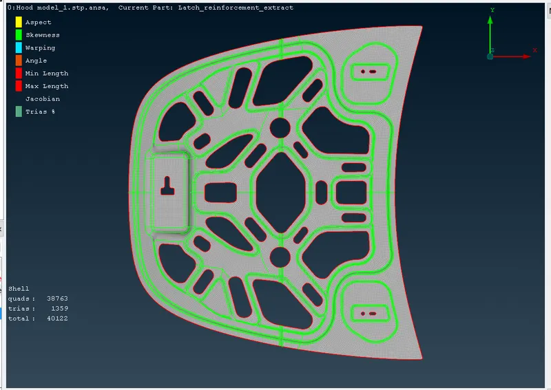
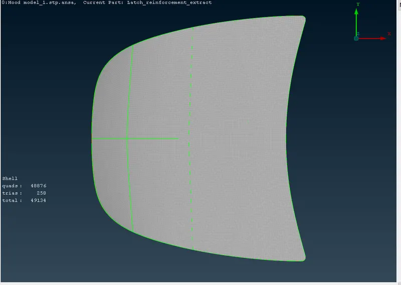
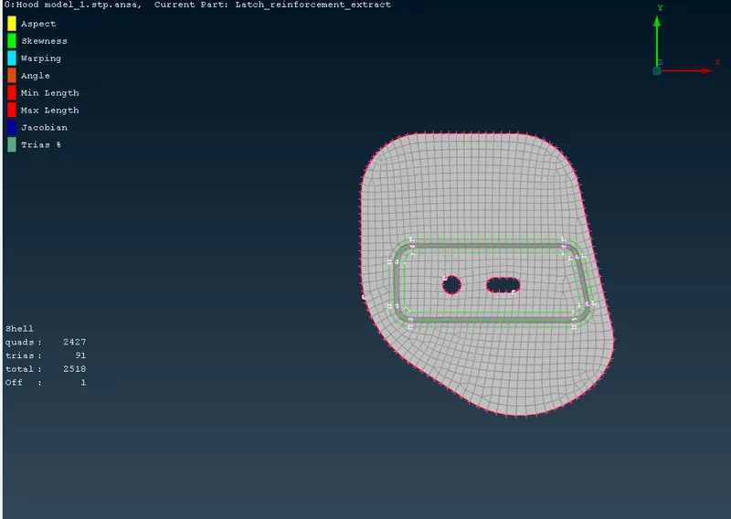
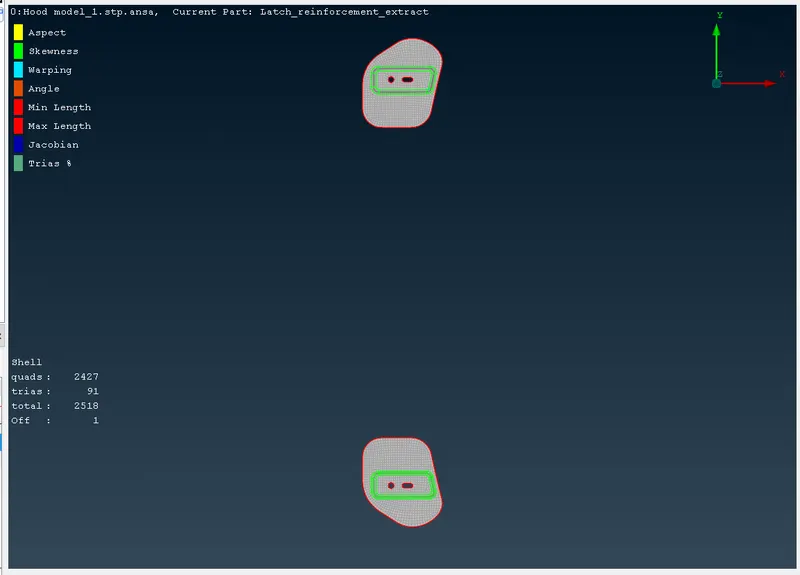
Meshing is the process of discretization of the CAD model into a so-called 'Finite-Element model or FE model'. Meshing is one of the core processes which makes the Finite element method possible, as it helps us convert a continuous problem with an infinite number of points into a discrete set of elements which then can be computed for the field variable and integrated over the whole domain.'
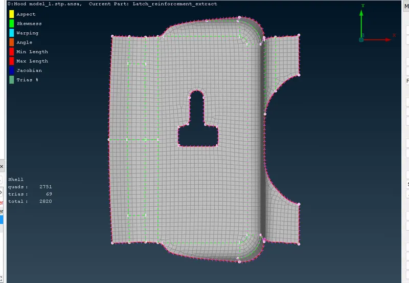
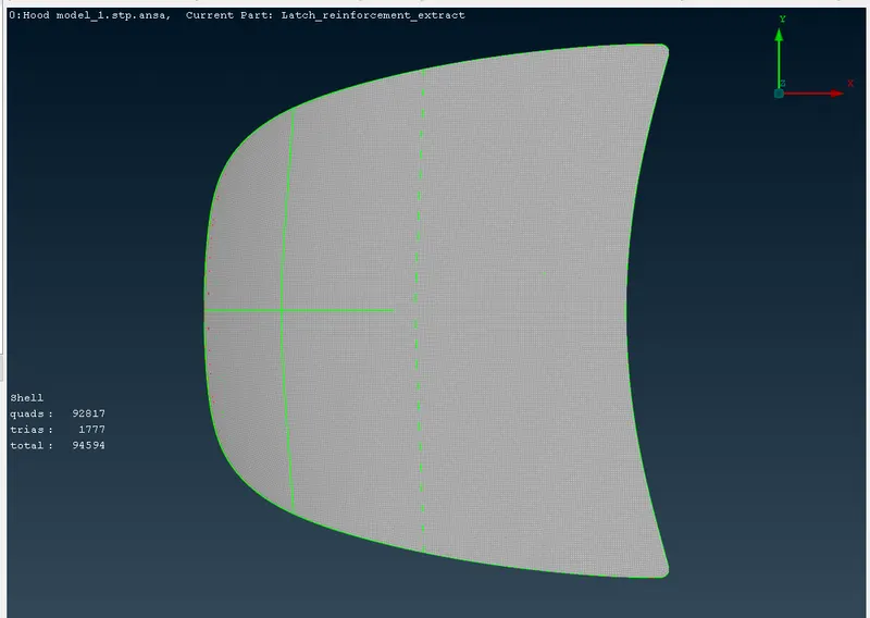
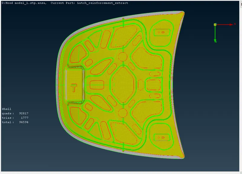
To assign a gap between 2 nodes we can use the macros option which is available in ANSA, by which you can assign a target element size of 5 by Mesh -> Perimeters -> length.
Assigning thickness:
Each and every time the ANSA itself assigns a thickness to the newly created component.
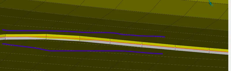
The command for assigning the thickness to the component is from the option through
menubar->tools ->quality ->presentation parameters ->draw shell as solid option is used.
Conclusion:
As per the required parameter, I have done my meshing of the component in a proper flow in ANSA with no quality criteria don't affect and i have attached the file.