Week 3 - 2D meshing for sheet metal
Aim:
To extract the mid-surface of the given vehicle hood component and carry out the geometry clean up and mesh the given hood component according to the given quality criteria.
Procedure:
1. Import the given model into ANSA workspace.
Check the imported model for number of parts it has, the given model contains five parts
- Latch reinforcement
- Right hinge reinforcement
- Left hinge reinforcement
- Outer extract
- Inner extract
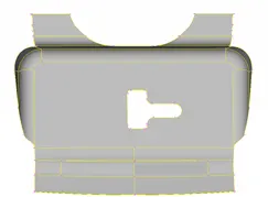
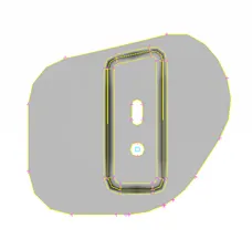
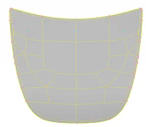
1.latch Reinforcement 1.2mm thick. 2.Hinge reinforcement 1.2mm 3.Hood Outer extract 0.75mm thick.
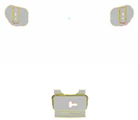
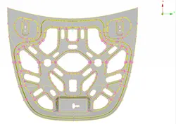
4.Hinge and latch placements in the model. 5.Hood inner extract 0.75mm thick.
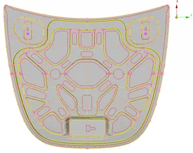
overall assembly of the model.
2. Geometry check.
Check the individual parts for any presence of free edges in the model, the hood is a sheet metal part, and it should not have any free edges before extracting the mid-surface.
The geometry check is carried on all the parts by going to TOOLS > CHECKS > Geometry

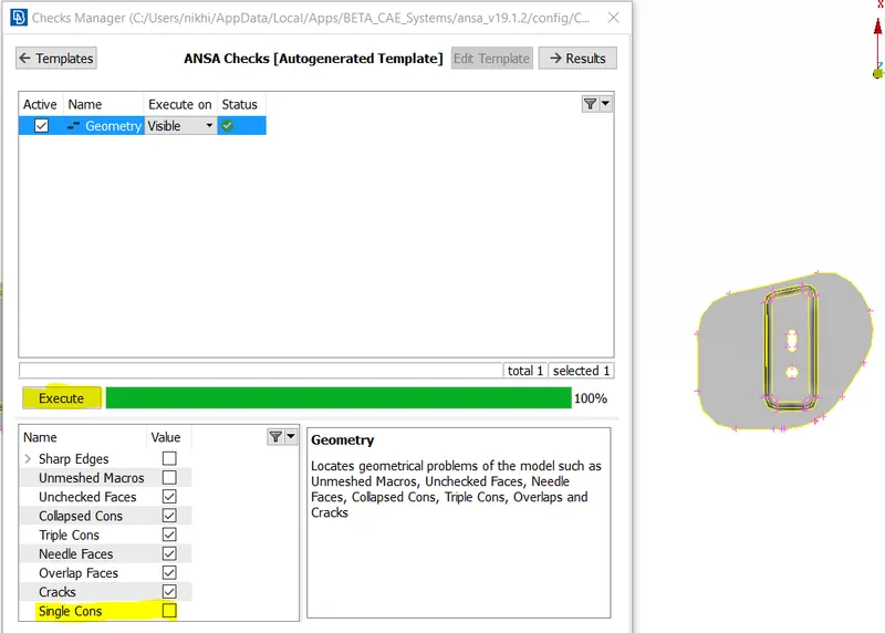
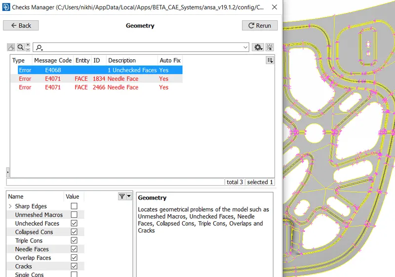
If any errors show up they can be auto cleared by going to, right click error > Fix, if its not cleared right click on the error and show only option will highlight the error area and it can be fixed manually by joining the edges or by creating the surfaces depending on the error.
3.Mid surface Extraction:
after clearing all the error in the model, measure the thickness of each part to extract the mid surface of the parts.

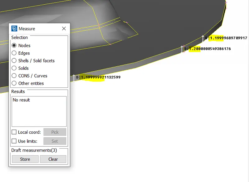
all the parts have different thickness value, hence appropriate value should be given while manually extracting the mid-surface.
TOPO > FACES > MID SURF > SKIN
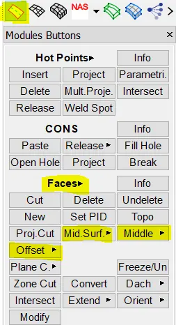
If auto mid-surface fails to extract the mid-surface, manual mid-surfacing is performed using offset or middle option from topo module.
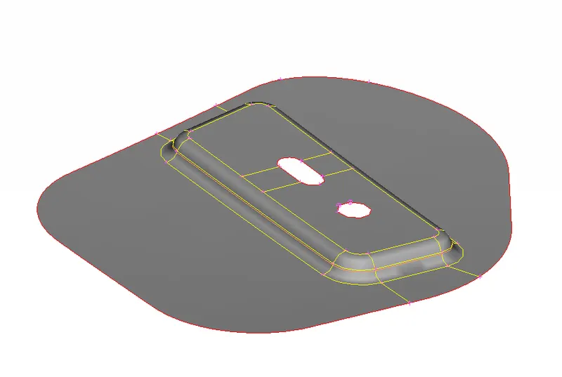
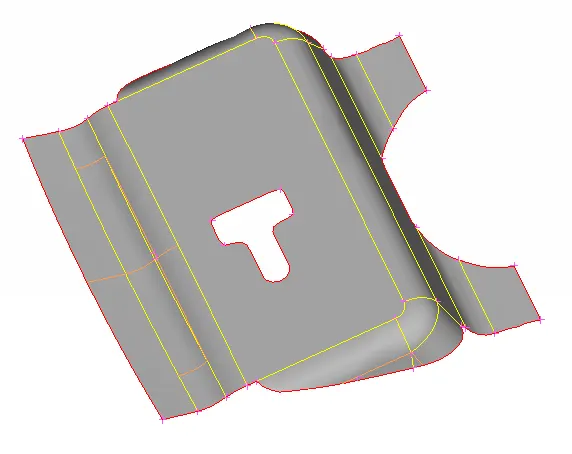
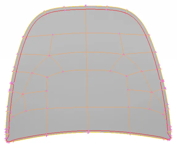
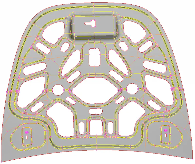
To prepare the parts for meshing the topology has to be cleaned based on the minimum element size, any feature below the minimum element size needs to be defetured if the feature is not important to capture, and edges which are in close proximity to each other needs to be taken care of to avoid the minimum element failure.
The orange line on the mid-surface in the above images show the lines which are joined (toggled) to achieve a structured mesh on the part
4.Quality criteria setup:


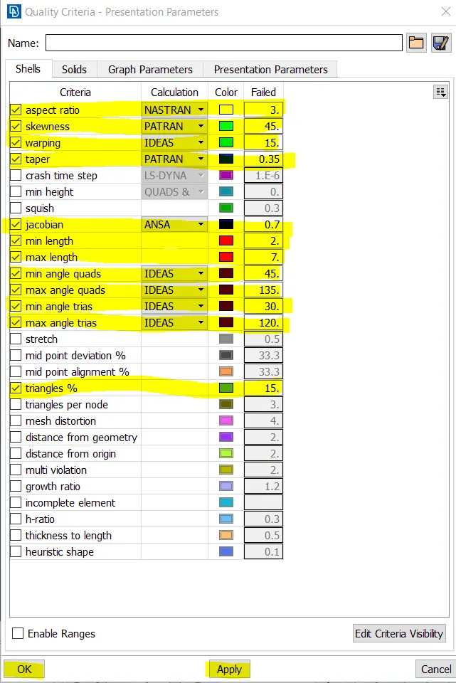
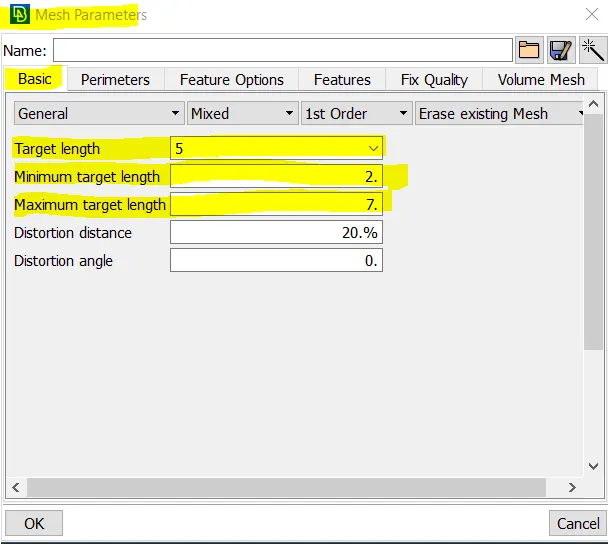
Quality criterial setup Mesh parameters setup
5. Meshing:
Once the mid surface extraction and geometry clean-ups are performed the parts are ready to be meshed.
To start the meshing switch to Mesh bar in the modules menu bar

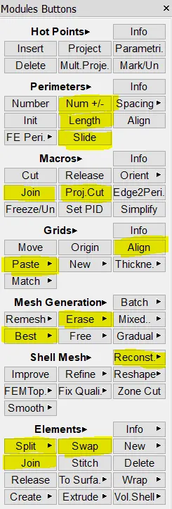
some of the most used options in meshing process are highlighted in the above image.
to start meshing the surface go to MESH GENERATION > BEST and select the surface to be meshed.
The meshed part can be checked for quality criteria by switching the drawing styles to hidden mode

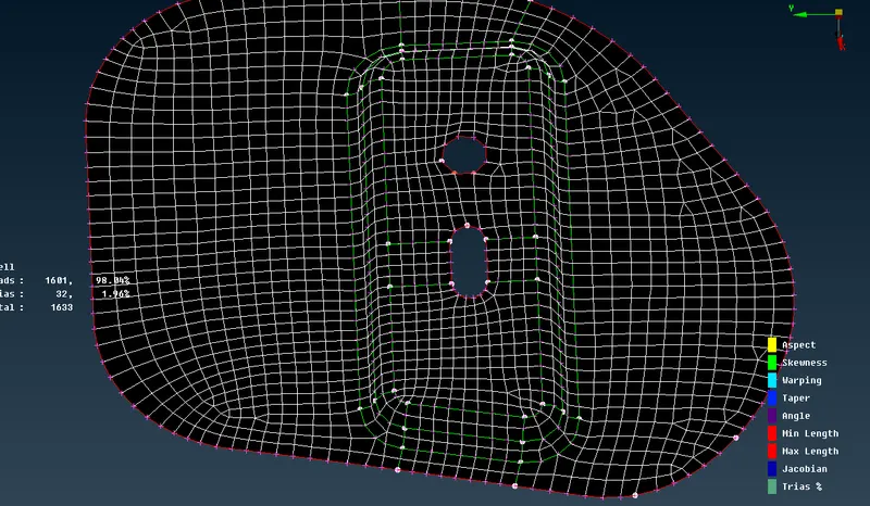
If the mesh fails for any quality the reconstruction option is used to Ramesh the surface, the opposite trias can be removed by joining them together and the to remove the tria elements split and join join can be used, swap option is used to take them away from the edges, and paste option is used to drag them out from the free edges.
since

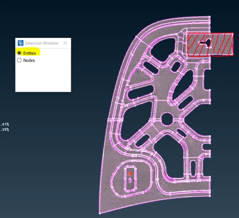
the whole part except for the surface hatched in red is selected to reflect.
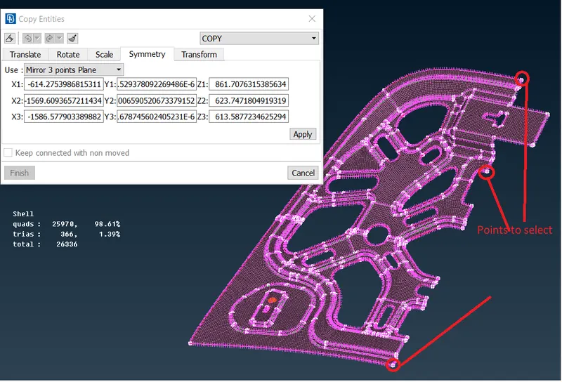
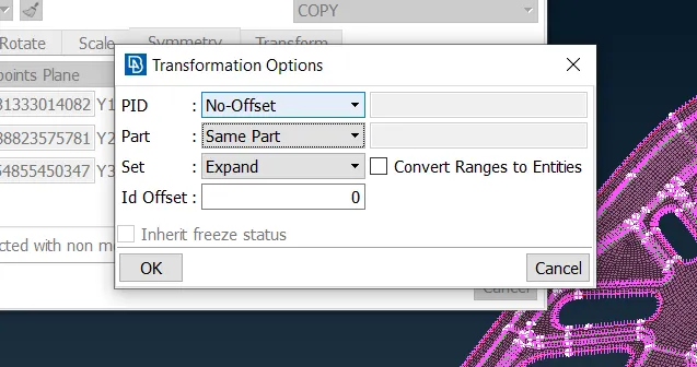
use three points plane and select the points as shown in the image above and press apply, select the PID and parts options and press ok, the mesh and the surfaces will reflect.
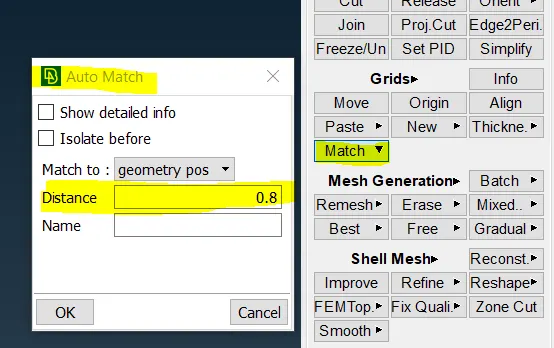
use TOPO > FACES > TOPO to fix the free edges at the midline, to fix the node connectivity go to MESH > GRIDS > MATCH > AUTO and specify distance for node connectivity.
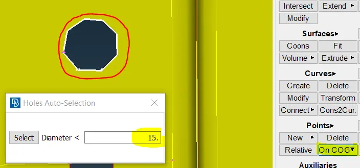
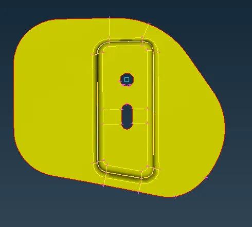
to perform the same option to the hinge reinforcement points at the centre of each circle is created and a point inbetween the two ponts is created as shown below using the TOPO module> POINTS > ON COG > EDGE specify the hole diameter and select the hole and apply.
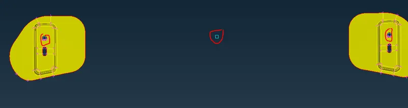
To perform the symmetry, select the middle node for first point and alter the value of only X-axis for 2nd point and for 3rd point alter the value of Z- axis only
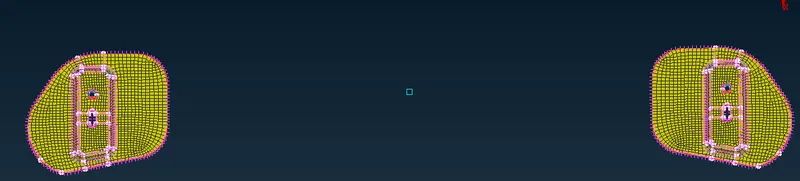
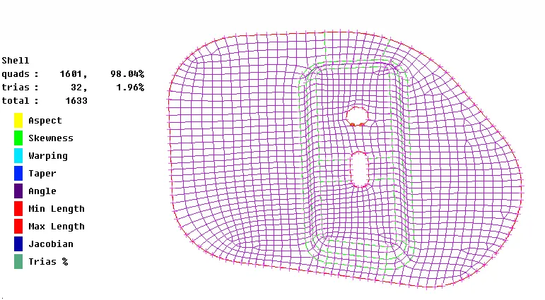
Hinge reinforcement mesh.
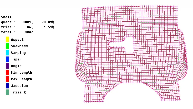
Latch reinforcement mesh.
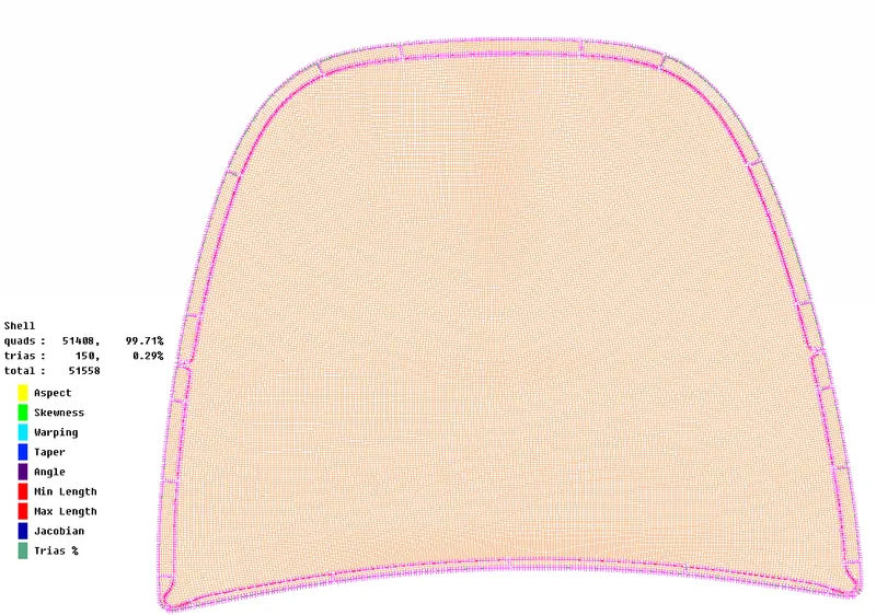
Outer panel mesh.
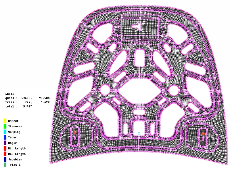
Inner panel extract mesh.
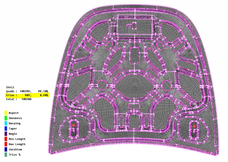
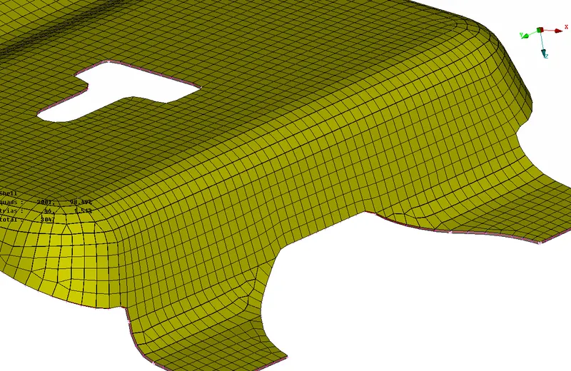
final assembly mesh.
From the above image in the final assembly mesh it is seen that the percentage of tria elements in the model is 0.9% which is less than the quality criteria value and their are no off elements in the model, which shows that their are no elements failing for the quality criteria.
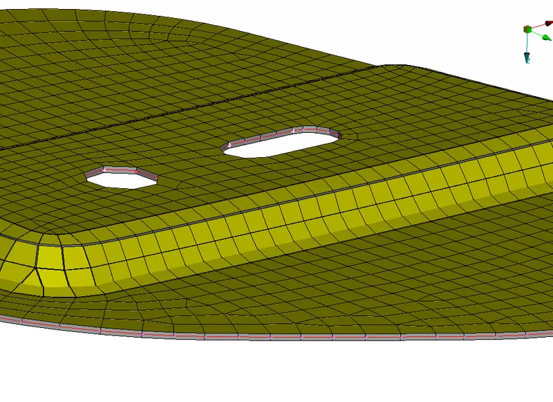
Property with appropreate thickness is applied to the meshed parts and 2D detailed view is shown for better visualization and possible check for the elements penetration.
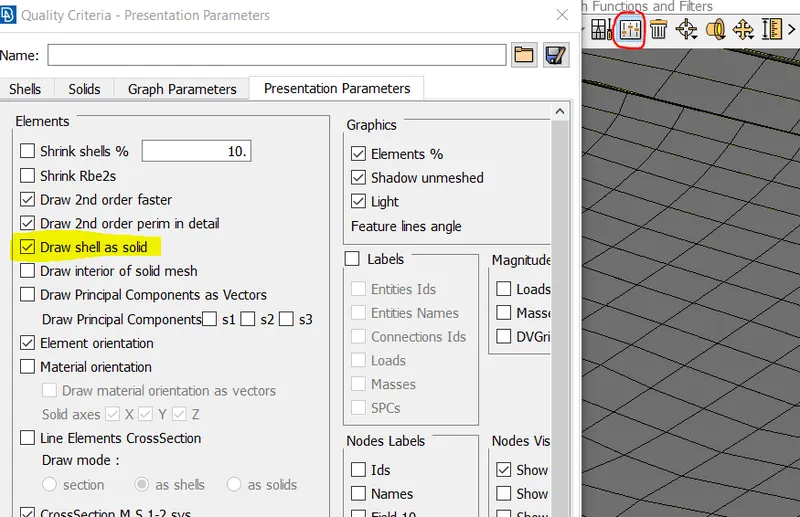
2D detailed view can be switched on by going to
UTILITIES > QUALITY CRITERIA > PRESENTATION PARAMETERS > DRAW SHELL AS SOLID (switch on the option)
Learning outcomes:
Geometry cleanup, midsurface extraction, topology cleanup, quality criteria file setup, 2d shell meshing on sheetmetal parts, fixing the Quality of failed elements.
Conclusion:
Conclusion:
The given hood model is imported and checked for geometric deformities and fixed the geometry, mid surface is extracted and topology clean is carried out to prepare the mid-surface for meshing, structural meshing is carried out on the mid-surface and element quality is maintained with low percentage of tria elements.