Week 3 - 2D meshing for sheet metal
Aim :
For the given Hood model, Take the mid surface for all the components after checking the geometrical errors and mesh the mid surface with the given element Quality criteria.
element Quality criteria.
|
S.No |
Quality Criteria |
Value |
|
1 |
Target/Average length |
5 |
|
2 |
Minimum Length |
2 |
|
3 |
Maximum Length |
7 |
|
4 |
Aspect |
3 |
|
5 |
Warpage |
15 |
|
6 |
Skewness |
45 |
|
7 |
Jacobian |
0.7 |
|
8 |
Minimum Quad Angle |
45 |
|
9 |
Maximum Quad Angle |
135 |
|
10 |
Minimum Tria Angle |
30 |
|
11 |
Maximum Tria Angle |
120 |
|
10 |
Tria Percentage |
15 |
PROCEDURE: -
Open the hood model.stp file. Go to File>Open.
We can now view the faces in gray and yellow. Gray color represents the positive side of th
faces while Yellow the negative one. The orientation is currently random. Activate the
Faces>Orient>Visible function.
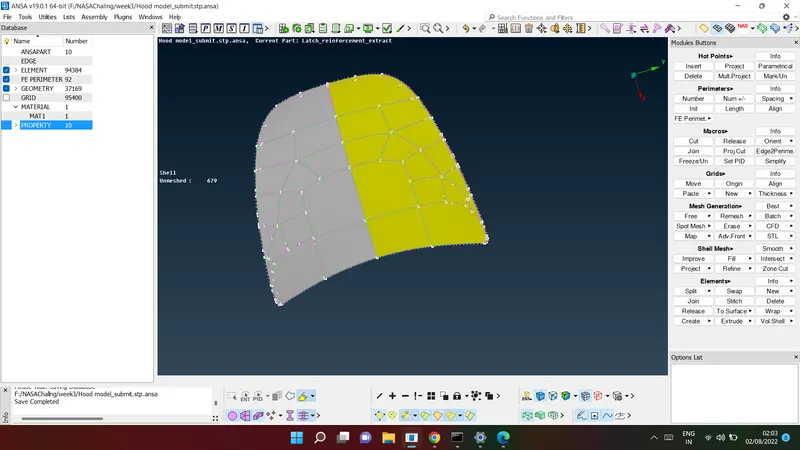
- Check the geometry to identify the problematic areas. Click on the “Checks” button,
located in the “Tools” toolbar on the top of the screen and select “Geometry”. Keep the
default options and click Execute.
We will get different type of errors such as needle face, crack between cons, tripple cons
and missing surface. In order to solve the tripple con release the triple con using the
"Release" tool in cons. Then select the tripple con and do middle click. Use the Faces>Topo
tool to combine the surfaces.
Depending on the type of the problem ansa also offers the option to automatically fix it.
Select the problems from the check manager window and click right mouse button and
choose fix from the list
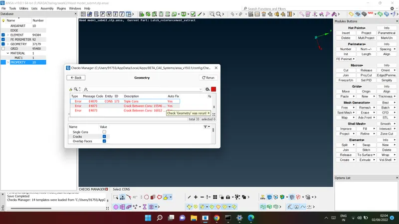
after fixing the geometry cleanup
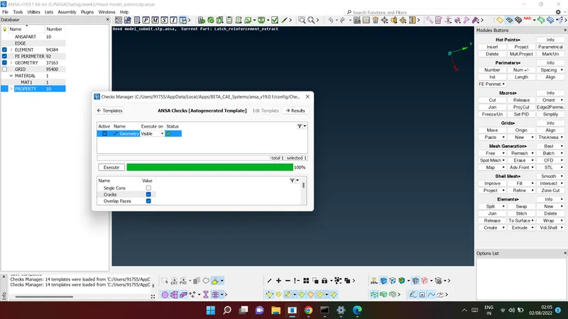
Now midsurface
- Now midsurface is extracted using the Skin option under Topo>Faces>Midsurface tool. As
the thickness of the sheet metal component is constant throughout, Skin option will save u
a lot of time.
The Macros>SET PID function can be used to assign multiple different PIDs to selected
macro areas. Assign thickness of 0.75 to the INNER and OUTER Extract. Also, the thickness fo
latch reinforcement and hinge reinforcement is 1.2.
Activate the Auxiliaries>Fine function found in the TOPO Menu. Left click a couple of times o
the crosshatches of the faces in order to reduce the resolution length.
To eliminate the red cons between surfaces the Faces>Topo function can be used, select
with a box selection the area and confirm with the middle mouse button.
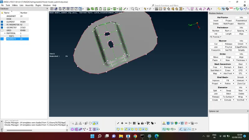
- Delete the hot points by Hot Points>Delete function and select with the left mouse button.
Activating the “Slide” flag allows us to select nodes of a perimeter and slide them along it.
This is useful in order to change the orientation of a hole.
We will assign a uniform distance between perimeter Nodes or element length. Click the
Perimeters>Length function. Select all the Macro Areas with the left mouse button making a
box selection. Confirm with the middle mouse button. Type in a value of "5" in the length
field and press Enter.
Perimeter segment that is too short to have even one perimeter node. Activate the
Mesh>Perimeters>Num+/- function. Use the left mouse button to increase the number of
nodes and right mouse button to decrease the number.
ANSA provides shell mesh quality check of the generated Geometry Mesh elements. Select
the threshold value of each quality criterion and the criteria has to be active for each
quality check. Similarly we have to set the meshing parameters. Set the target length as
5mm, minimum element length as 2mm and maximum element length as 7mm.
|
S.No |
Quality Criteria |
Value |
|
1 |
Target/Average length |
5 |
|
2 |
Minimum Length |
2 |
|
3 |
Maximum Length |
7 |
|
4 |
Aspect |
3 |
|
5 |
Warpage |
15 |
|
6 |
Skewness |
45 |
|
7 |
Jacobian |
0.7 |
|
8 |
Minimum Quad Angle |
45 |
|
9 |
Maximum Quad Angle |
135 |
|
10 |
Minimum Tria Angle |
30 |
|
11 |
Maximum Tria Angle |
120 |
|
10 |
Tria Percentage |
15 |
Click the Mesh>Mesh Generation>Best function. Select with the left mouse button the
macros of the component and confirm with the middle mouse button.The Reconstruct
option means erase and mesh from new with the current algorithm and settings.
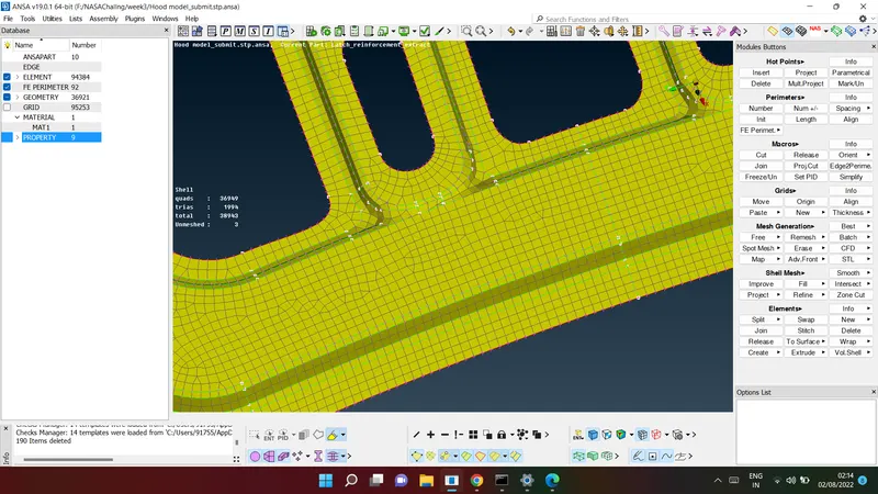
- Mesh improvement can be carried out using various tools. Split option can be found in
Elements in Mesh deck. It can be used to eliminate the rotating quads and trias elements.
Also, join option can be used to remove the edge and convert two side by side tria into
quad element.
The function Elements>Swap can be used in order to swap a common edge of two
elements. After that apply Mesh>Shell mesh>Smooth command to make the small
adjustment needed to get the curvature for the entire mesh.
Also paste tool can be used to eliminate two opposite trias and coarser the mesh pattern.
PASTE option can be found in GRIDS in the MESH deck
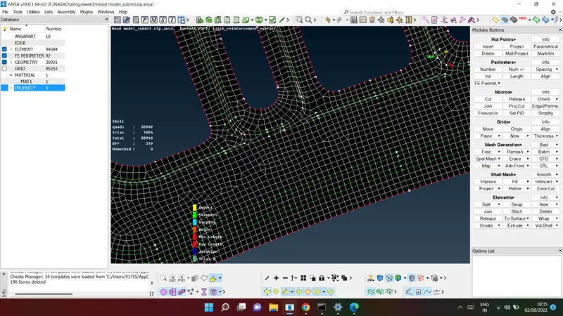
CONCLUSION: -
1. Performed the manual topology cleanup, midsurface extraction and 2-D meshing for all
the components of the hood, also asign thickness as per component.
2. Achieved the mentioned quality criteria for all the components of the hood.