Week 3.2 - 2R Robotic Arm Challenge
2R FORWARD KINEMATIC ROBOT ARM
OBJECT:
Write a program to solve forward kinematics of 2R Robotic Arm.
THEORY:
A robotic arm is a type of mechanical arm, usually programmable. The arm may be whole of the mechanism or maybe a part of a more complex robot. The links of such a manipulator are connected by joints, allowing either rotational motion or translational displacement. The links of the manipulator can be considered to form a kinematic chain. The terminus of the kinematic chain of the manipulator is called the end effector. An end effector is a device at the end of a robotic arm, designed to interact with the environment.
Robot kinematics refers to the analytical study of the motion of a robot manipulator. Formulating the suitable kinematics models for a robot mechanism is very crucial for analysing the behaviour of industrial manipulators.
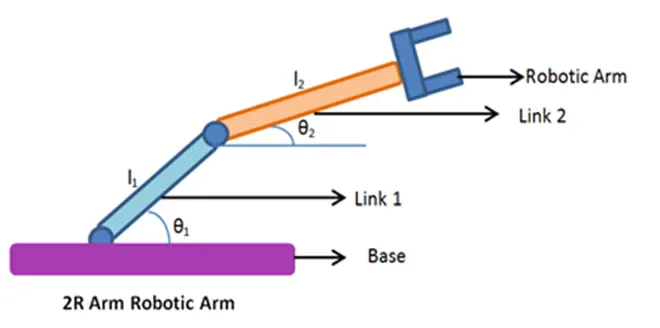
Fig. 1
Calculating the position and orientation of the end effector in terms of the joint variables is called Forward kinematics. In order to have forward kinematics for a robot mechanism in a systematic manner, one should use a suitable kinematic model. Forward kinematics problem is straightforward and there is no complexity deriving the equations. Hence, there is always a forward kinematics solution of a manipulator.
Explanation and Procedure for calculation:
As the above fig. 1 the base is withstanding the all body of the 2R(Rotational) robot.
STEP 1: Calculating the position of Link 1.
From the fixed support, the initial value of X and Y for the Link 1(X0,Y0) and the final value (X1,Y1) with length L1 for angle θ1.
Starting Point of Link 1
X0 = 0
Y0 = 0
End Point of Link 1
X1 = L1*cosθ1
Y1 = L1*sinθ1
STEP 2: Calculating the position of Link 2.
For the Link 2 Starting Point is Ending point of the Link 1 i.e., (X1,Y1) are the starting point of Link 2 and (X2,Y2) are the ending point of the Link 2. The Link 2 has the length as L2 and angle as θ2.
Starting Point of Link 2
X1 = L1*cosθ1
Y1 = L1*sinθ1
End Point of Link 2
X2 = X1 + L2*cosθ2
Y2 = Y1 + L2*sinθ2
STEP 3: Creating Program
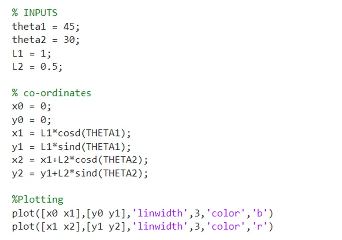
The program represents the Input as L1 = 1 and L2 = 0.5 In meters also the angles as Θ1 = 45
Θ2 = 30 In degrees. And providing the basic conditions and plotting by above step1 and step 2.
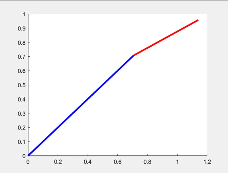
The above plot shows the output of the program for a particular angle.
STEP 4: Program Animation
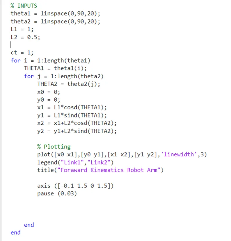
Adding the Multiple angles to the program using “linspace” command.
Taking FOR loop in condition for the repeating the different angle in plot to animate the robot arms. And providing Co-ordinates in one line to run program smother. Adding “Pause” command to execute the animation in visible way of every angle. Adding axis From and to of x and y axis. Before start of FOR loop add the contour(ct) as 1.
STEP 5: Creating a movie
To create movie type M(ct) = getframe(gsf) Just below the Pause(0.03) and below that ct=ct+1. To show of Movie have to create the below command and the movie will be created.
Where, ct represents every frame and getframe command represents to getting the current figure in the gcf window. Further we are creating “avi” file to get this movie.

FINAL MATLAB CODE:
clear all
close all
clc

% INPUTS
theta1 = linspace(0,90,20);       % Angle of Link 1
theta2 = linspace(0,90,20);       % Angle of Link 2
L1 = 1;                           % Length of Link 1
L2 = 0.5;                         % Length of Link 2

ct = 1;                           % contour value
for i = 1:length(theta1)          % FOR LOOP for theta 1
    THETA1 = theta1(i);
    for j = 1:length(theta2)      % FOR LOOP for theta 2
        THETA2 = theta2(j);
        x0 = 0;                   % Starting point of Link 1 with angle theta 1
        y0 = 0;                   % Starting point of Link 1 with angle theta 1
        x1 = L1*cosd(THETA1);     % Ending point of Link 1 and Starting point of Link 2 with angle theta 2
        y1 = L1*sind(THETA1);     % Ending point of Link 1 and Starting point of Link 2 with angle theta 2
        x2 = x1+L2*cosd(THETA2);  % Starting point of Link 2
        y2 = y1+L2*sind(THETA2);  % Ending point of Link 2

        % Plotting
        plot([x0 x1],[y0 y1],[x1 x2],[y1 y2],'linewidth',3)  % Plot of Robot Arms
        legend("Link1","Link2")
        title("Foraward Kinematics Robot Arm")

        axis ([-0.1 1.5 0 1.5])    % x and y axis values i.e. [x(start) x(end)] [y(start) y(end)]
        pause (0.03)               % Pause time
        M(ct) = getframe(gcf);     % Movie creation
        ct = ct+1;

    end                            % END FOR LOOP
end                                % END FOR LOOP

movie(M)
videofile = VideoWriter("Forward_Kinematic_robot_arm","Uncompressed AVI");
open(videofile)
writeVideo(videofile,M)
close(videofile)
The above program is solution for the 2R robot arm for different angle of motion.
The Movie file link is shown below
https://www.youtube.com/watch?v=dLcTGKv3VG8
CONCLUSION:
Hence, we are able to program the 2R robot arm, with the help of above program.In the program we used for angle as
theta1 = linspace(0,90,20)
theta2 = linspace(0,90,20)
to execute the progra in the different angles to show the motion of robot arm.
Also we can get multiple outputs such as we can move the arm in multiple directions and mutiple speeds.
Also we can able to to make new program such as 3R robotic arm.