Week 2 Railwheel and Track
Objective
To perform a static analysis on a Railwheel and Track model following the objective given below.
Case 1: Multiply the bearing load by 5 times and compare the results with the load of 100000 N. Compare the Total Deformation, Equivalent stress, and the life under both the loads.
Case 2: Implement a User-defined result and calculate the Total Deformation from this result and check if it is the same as that obtained by the inbuilt result by ANSYS for a load of 100000 N.
Procedure
- A new Ansys file was opened and a static structural module has been dragged onto the project scheme
- The material for the model was chosen as structural steel from the engineering data.
- The given model of the rail and the track were imported to the geometry tab and then opened the model tab to assign further conditions.
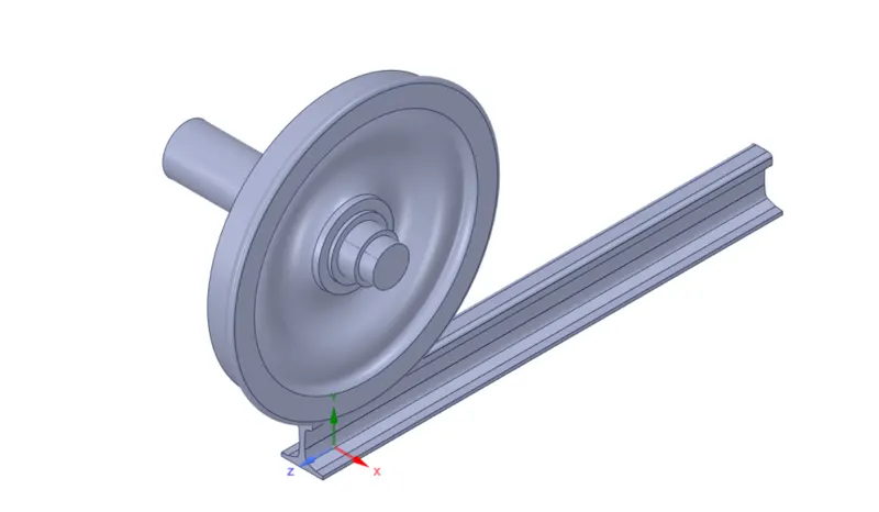
- The model was renamed by pressing the F2 key on the keyboard, also assigned the material to each part accordingly.
- Expand the connection to see the contacts and select both the contact region>right-click>Re-name based on the definition. Once it's done flip the contact as well as the target by right-clicking the same. With this two type of connection was established. One is between the rail and the well and the other with the wheel and the shaft.
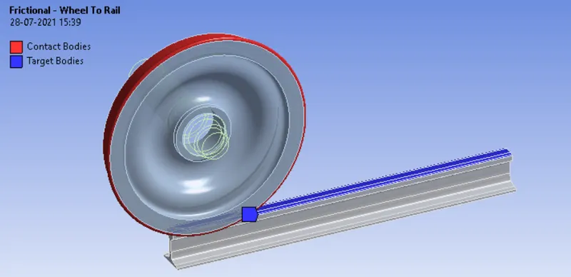
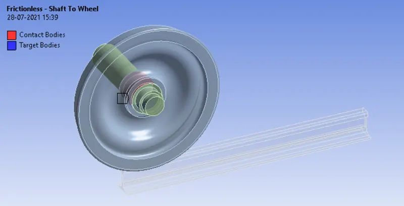
- So for the wheel and rail, a frictional type was chosen with a frictional coefficient of 0.3. For shaft and wheel contact a frictionless type was chosen.
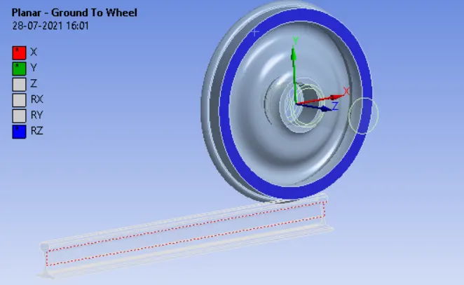
- In this simulation, we are having a translational joint that is going to rotate as well as translate along the track and need to make sure that the wheel stays in one plane, so need to provide a planar joint. Also, a fixed support to fix the rail track.
- The track was fixed by connections>joint>body-ground>fixed and both sides of the track were selected.
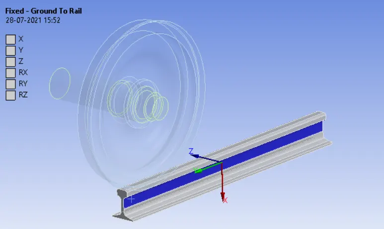
- To provide the translational movement, Connection>body-ground>translational>select the shaft >apply. The direction of the motion has to be checked and if need a correction it can be done by expanding the translational tab and changing the principal axis. So axis will be reoriented in the direction of translation.
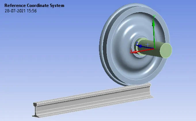
- A planar joint has been defined by connection>body-ground>planar>select the face>apply.
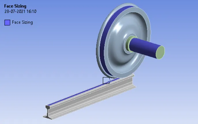
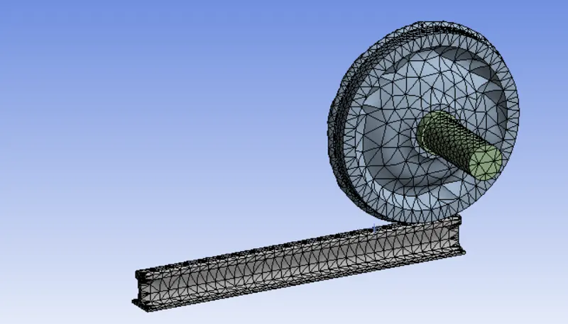
- The model has been meshed with an element size of 50mm and to refine the meshed on the contact regions, select those regions and right-click mesh>insert>sizing and assign the value of 35mm.
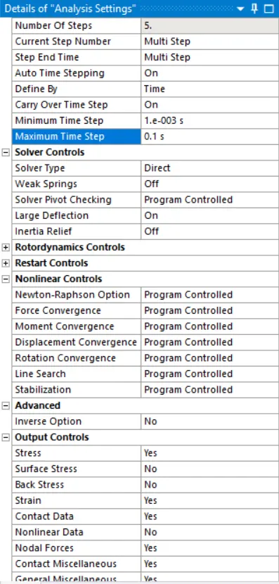
- The load and solver definition was done from the analysis setups. Here the wheel is translated to a distance of 500mm with 100mm in each step. Other changes made are shown below.
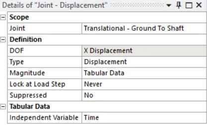
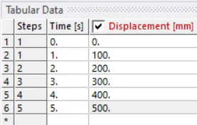
- The load for the simulation was assigned by right-clicking static structural>inset>joint load. Here it's been translated to a distance of 500mm in the x-direction.
- Apart from that other load acted upon the wheel are the varying load ie, the load imposed by the carriage will be transferred to the shaft thereby loaded to the wheel through this particular hole shown below and a bearing load was applied. Load>bearing load>
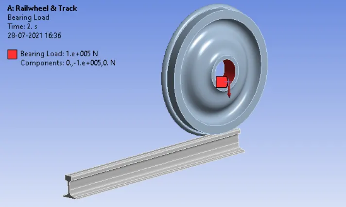
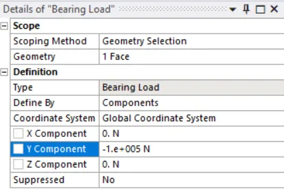
- A per the objective another case was performed by changing the bearing load to 500000N.
- From the solution, the output for Total Deformation, Equivalent stress, and the life under loads were requested.
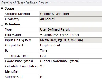
- For case 2 a user-defined result for total deformation was found for the total displacement as shown below.
Results
- The static analysis on a RailWheel and track was performed and satisfied all the results. The results got from the simulation are discussed below.
Case1
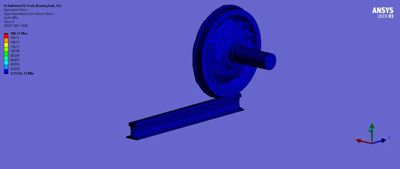
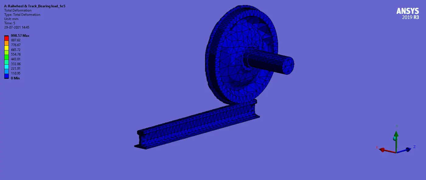
For the case1 simulation was performed by looking into two bearing loads of magnitude 100000N and 500000N. The output for 100000N from the simulation is shown below.
Equivalent stress
Total deformation
Life under the load of 100000N
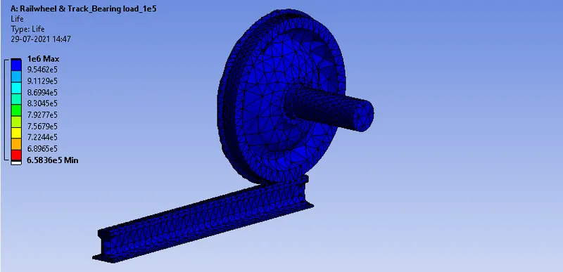
- Similarly, the plots for 500000N bearing loads were also found out and tabulated the results obtained.
Comparison

- From the table, it's been observed that the total deformation for the two loads is almost the same though the load with 500000N is a bit more. The maximum value for total deformation was found to be 998.74mm.
- The maximum life of the assembly for both cases is the same.
- The equivalent stress for the load of 500000N is very high when compared to 100000N and is found to be 380.36MPa.
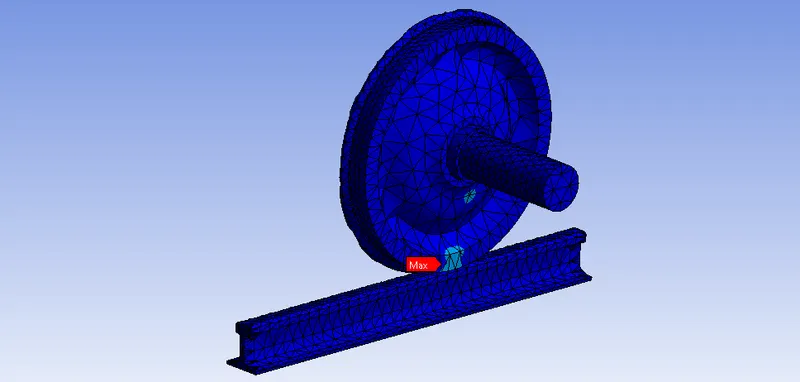
- The maximum stress was found to be more at the contact region of the track and the wheel as shown in the figure above.
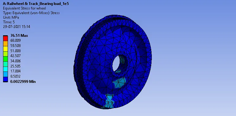
Equivalent stress for the wheel part under the bearing load of 100000N
Equivalent stress for the wheel part under the bearing load of 500000N
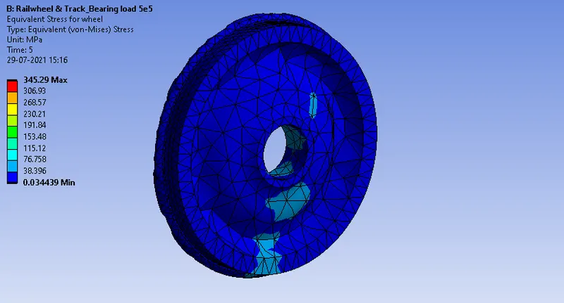
- Here also the when under the bearing load of 500000N has the maximum stress value.
Case 2
- For case 2 the output got from the user-defined result by providing the expression (sqrt(Ux^2 + Uy^2 + Yz^2)) is compared with the result of total deformation requested as output from the analysis set up.
User-defined result (Displacement)
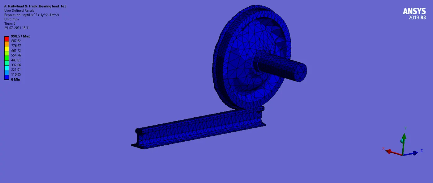
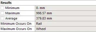
- Total Deformation with an inbuilt result and user-defined result was found to be the same. The maximum value for total displacement was found to be 998.57mm.
Conclusion
- The simulation for the rail wheel and track has been performed successfully and all the objectives are satisfied. When the magnitude of the bearing load was increased the stresses were found to be more. ANSYS workbench default pull-down menu post-processing options are more limited but they can still be accessed via the User Defined Results. With this, the result got for total deformation under this user-defined result and the inbuilt result compared and found out to be the same.
.............................................................................................................................................................................................................
File: https://drive.google.com/drive/folders/1QmL8XnpIKBqnn8t1cKXIf6hzSsGyjhLl?usp=sharing