Week 2 Railwheel and Track
- Objective
- Multiply the bearing load by 5 and compare the results to the 100000 N load (As done in week 2 video). Under both loads, compare total deformation, equivalent stress, and life.
- Implement a User specified result, calculate the Total Deformation from it, and compare it to the result generated by ANSYS's inbuilt result with a load of 100000 N.
- Case Setup and Execution
- Below are the points to be followed for case setup and execution.
- Geometry
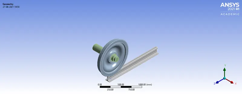
- Import the geometry provided to you in workbench.
- Material
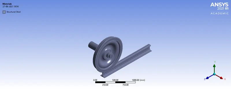
- Keep the material default (structural steel) for this simulation.
- Connections
- Contacts
- Ansys would have made automatic contacts.
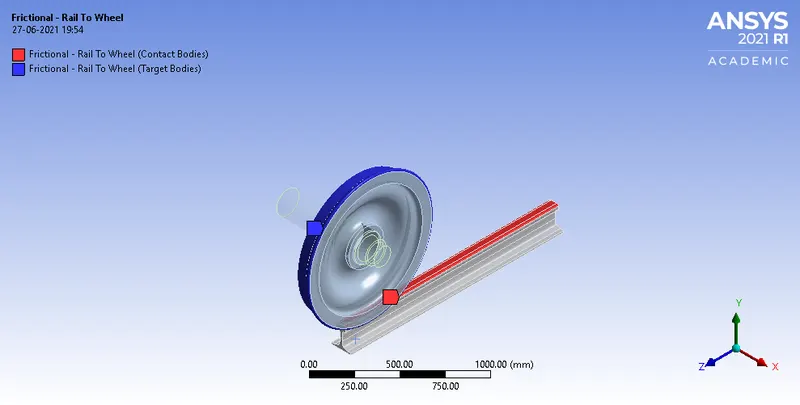
- Change the contact between wheel and rail from bonded to friction with co-efficient of 0.3
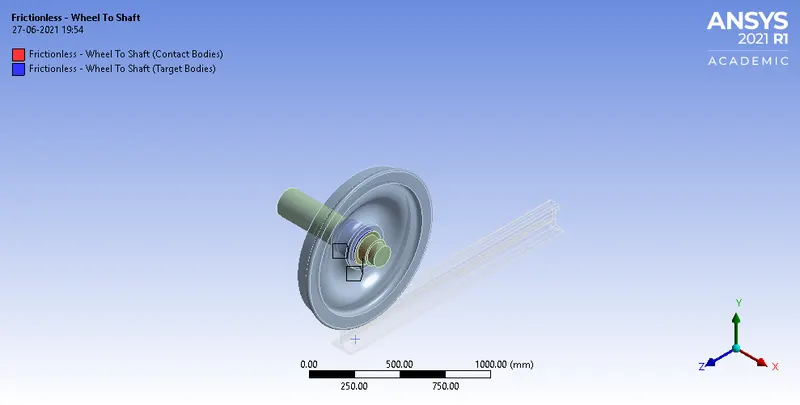
- Change the contact between shaft and wheel from bonded to fricitonless.
- Joints
- Below is the list of joints to be applied.
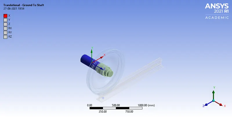
- Joint 1
- Connection Type - Body to Ground
- Type - Translation
- Scope - Shaft
- Joint 2
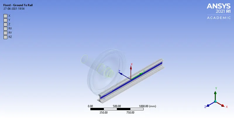
- Connection Type - Body to Ground
- Type - Fixed
- Scope - Sides of rail track
- Note :- The direction should be changed in so that X axis is in the direction of the displacement.
- Joint 3
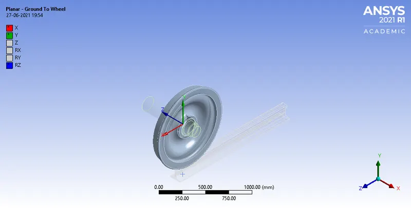
- Connection Type - Body to Ground
- Type - Planar
- Scope - Flate side face of the wheel
- Joint 1
- Below is the list of joints to be applied.
- Contacts
- Meshing
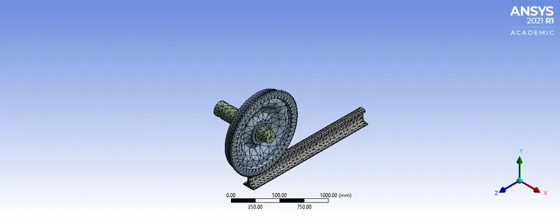
- Global Size = 50 mm.
- Face Sizing = 35mm.
- Select the contact faces where actual displacement is going occur.
- Boundary Condition
- Analysis Settings
- No. of steps - 5
- Step 1
- Auto Time Stepping - Program Controlled
- Solver Type - Direct
- Large Deflection - ON
- Force Convergence - ON
- Output Controls
- Change all the output controls to YES
- Step 2 - Step 5
- Auto Time Stepping = ON
- Define By - Time
- Carry Over Time Step - ON
- Minimum Time Step - 1E-003s.
- Maximum Time Step = 0.1s.
- Step 1
- No. of steps - 5
- Analysis Settings
- Load Conditions
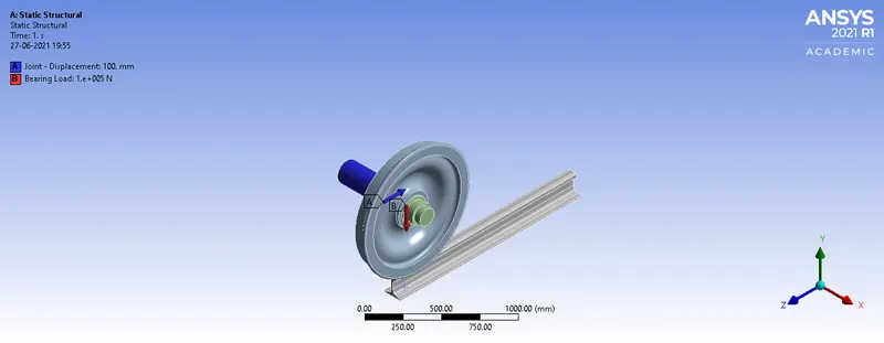
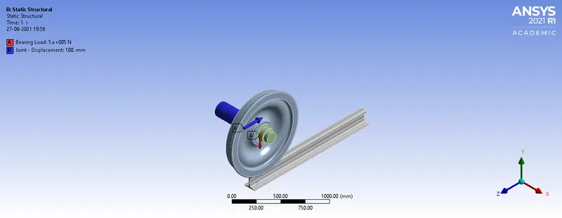
- Load 1 - Bearing Load
- On the inner diameter of wheel
- Define By - Components
- Axis Y - [-1e + 05] N
- Joint Load
- Type Displacement
- Give displacement of 100 mm for each increament for each step.
- Load Case 1
- Load Case 2
- Load Case 1
- Load 1 - Bearing Load
- Geometry
- Below are the points to be followed for case setup and execution.
- Results of Case 1 - Bearing Load [1E + 005] N
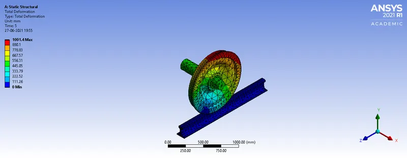
- Total Deformation
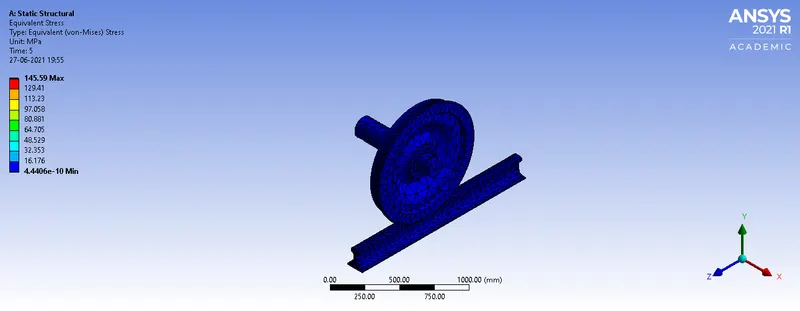
- Equivalent Stress
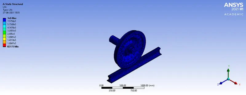
- Life
- User Defined Result
- use the following expression = sqrt( UX^2 + UY^2 + UZ^2 )
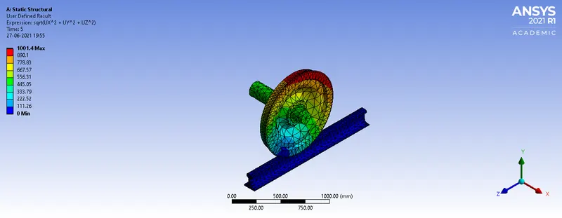
- Total Deformation
- Results of Case 2 - Bearing Load [5E + 005] N
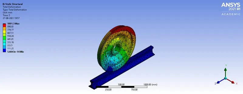
- Total Deformation
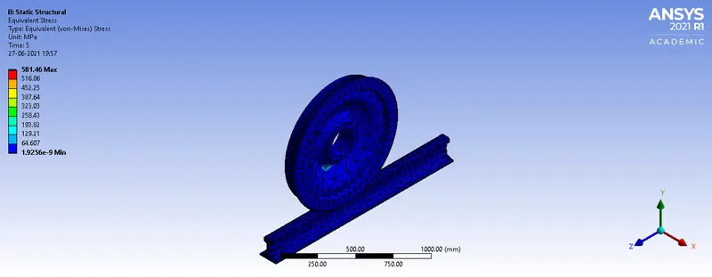
- Equivalent Stress
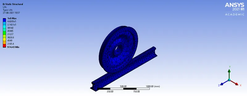
- Life
- User Defined Result
- use the following expression = sqrt( UX^2 + UY^2 + UZ^2 )
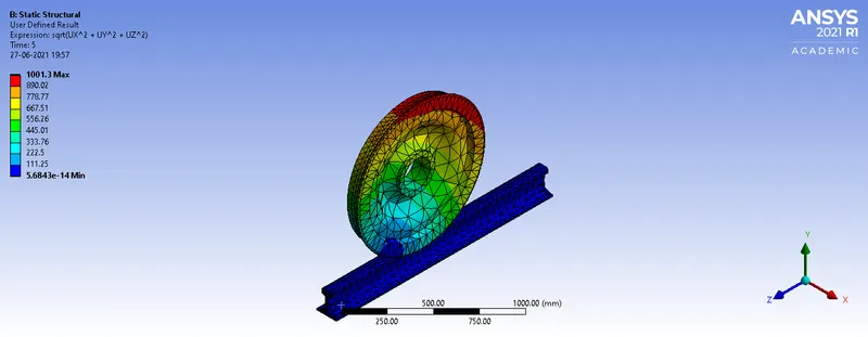
- Total Deformation
- Comparing the results
-
Cases Total Deformation (Max) mm Equivalent Stress (Max) MPa Life Cycles ( Min ) User defined result (mm) Case 1 1001.4 145.59 82175 1001.4 Case 2 1001.3 581.46 974.43 1001.3
-
- Conclusions
- Above results show that Equivalent Stress in Case 2 is more than Case 1.
- And henceforth life cycle of the system in case 2 decreases significantly compared case 1.