Week 2 Bevel Gear Challenge
- Objective
- Explaining Grid Dependency Test and its Uses
- Perform a grid dependency test for bevel gear simulation with different mesh sizes as follows ( 6,5, and 4 mm )
- Solve for Equivalent Stress , Equivalent Strain and Total Deformation
- Grid Dependency Test
- The grid dependence test is used to see how the solution changes depending on the grid size by running the simulation with a revised mesh. The finer the mesh, the higher the accuracy of the result, but it comes at a cost in terms of computation time and processing power. Because solutions are interpolated at the nodes to obtain an approximation result, the greater the number of nodes and elements, the longer and more powerful the computation required to finish the simulation.
- As a result, the grid dependency test aids in establishing the appropriate mesh size for obtaining accurate results while keeping time and power costs in mind. Because the results are approximate, more mesh refinement would result in a minuscule percent change in the result, but would simply raise the computing cost.
- Case Setup and Execution
- Below are the steps for the case setup.
- Geometry
- Import the geometry provided to you.
- Open the geometry in spaceclaim
- Remove out the material which is not required for the simulation.
- Materials
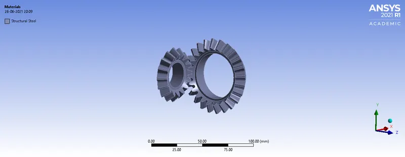
- Keep the material default ( Structural Steel ).
- Keep the material default ( Structural Steel ).
- Connections
- Contacts
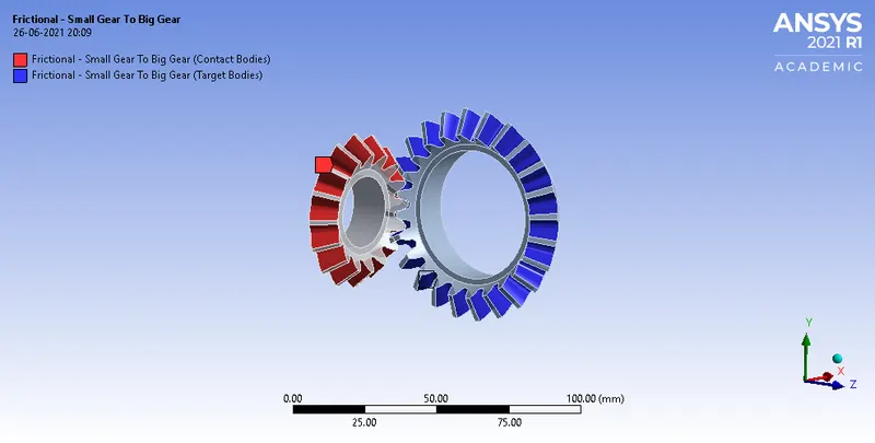
- Create the contact between all the teeth surfaces of both the gears.
- Change the contact type to friction with a co-efficient of 0.2
- Change the behavior to symmetric
- Chagent the contact formulation to Augmented Lagrange.
- Change the Interface treatment to Adjust to Touch.
- Joints
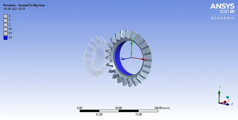
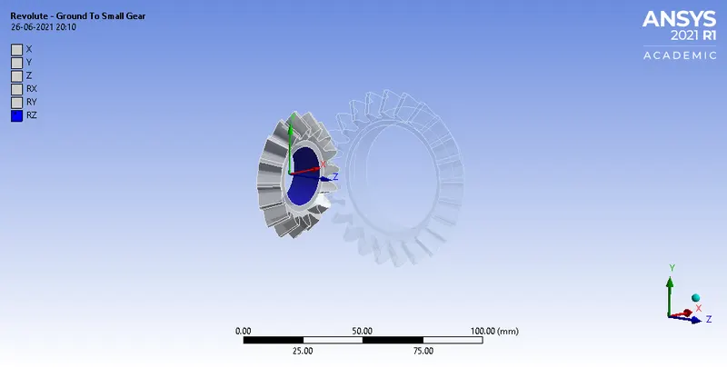
- Give body to ground joint to both the gears selecting the ID of the both gears.
- Change the joing type to revolute.
- Contacts
- Mesh
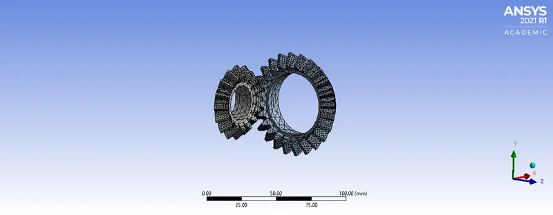
- Select all the contact faces and give them sizing mesh.
- Change the element size to 1.75 mm.
- Chang the global element size according to the cases.
- Case 1 - 6 mm.
- Case 2 - 5 mm.
- Case 3 - 4 mm.
- Geometry
- Below are the steps for the case setup.
- Boundary Condition
- Analysis Settings
- Change the analysis settings to the following.
- Total no. of Steps - 6
- Auto time stepping - ON
- Define by - Time
- Initial Time Step - 0.2s.
- Minimum Time Step - 0.1s.
- Maximum Time Step - 1s.
- Change the analysis settings to the following.
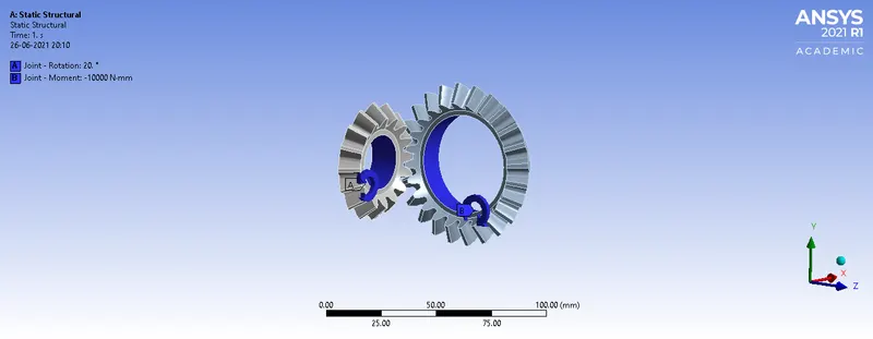
- Joint Load 1 - Big Gear
- Type - Moment
- Give the moment of -10000 N-mm to all the step 1 to step 6.
- Joint Load 2 - Small Gear
- Type - Rotation
- Give the rotation of 20 deg in increment to the step wise.
- Analysis Settings
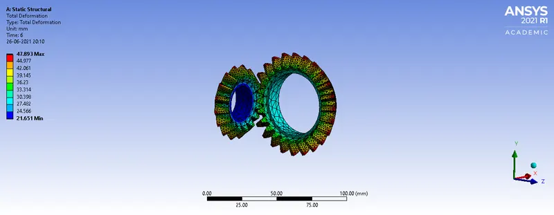
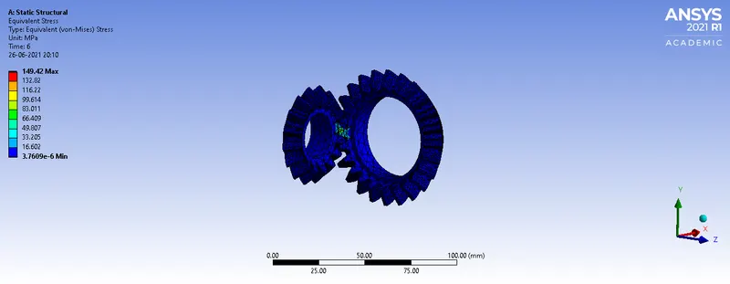
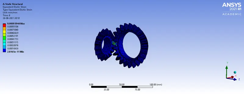
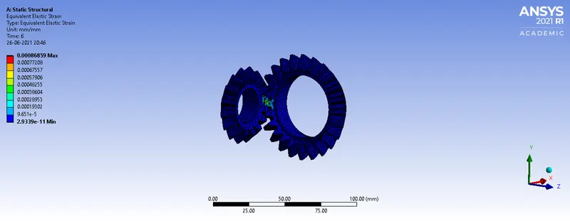
- Results of Case 1
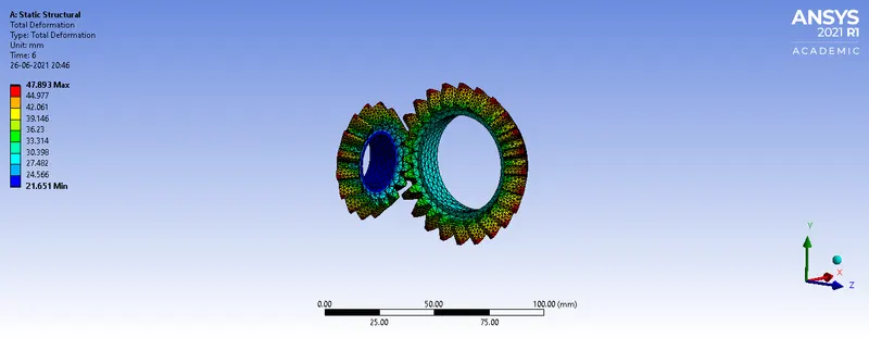
- Total Deformation
- Maximum Deformation in Case 1 is
- Minimum Deformation in Case 1 is
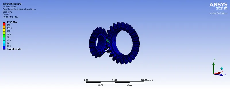
- Equivalent Stress
- Maximum Equivalent Stress in Case 1 is
- Maximum Equivalent Stress in Case 1 is
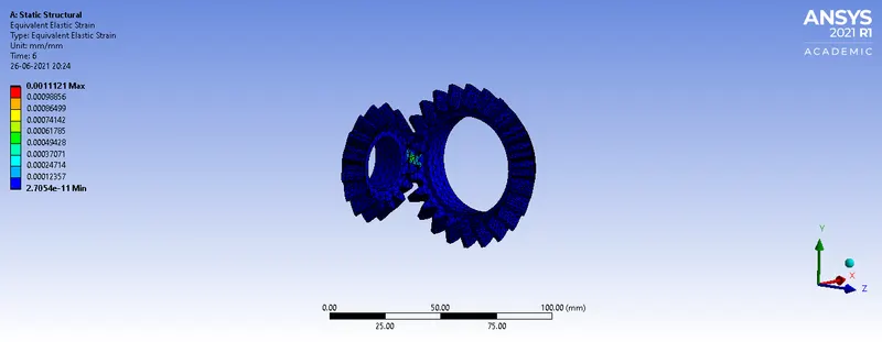
- Equivalent Strain
- Maximum Equivalent Stress in Case 1 is
- Maximum Equivalent Stress in Case 1 is
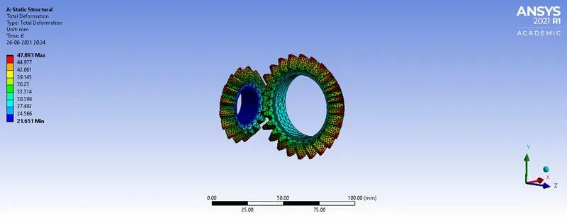
- Total Deformation
- Results of Case 2
- Total Deformation
- Maximum Deformation in Case 2 is
- Minimum Deformation in Case 2 is
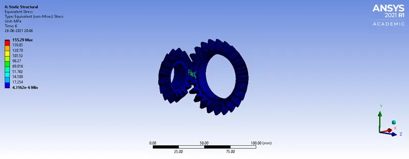
- Equivalent Stress
- Maximum Equivalent Stress in Case 2 is
- Maximum Equivalent Stress in Case 2 is
- Equivalent Strain
- Maximum Equivalent Strain in Case 2 is
- Maximum Equivalent Strain in Case 2 is
- Total Deformation
- Results of Case 3
- Total Deformation
- Maximum Deformation in Case 3 is
- Minimum Deformation in Case 3 is
- Equivalent Stress
- Maximum Equivalent Stress in Case 3 is
- Maximum Equivalent Stress in Case 3 is
- Equivalent Strain
- Maximum Equivalent Strain in Case 3 is
- Maximum Equivalent Strain in Case 3 is
- Total Deformation
- Comparing the results
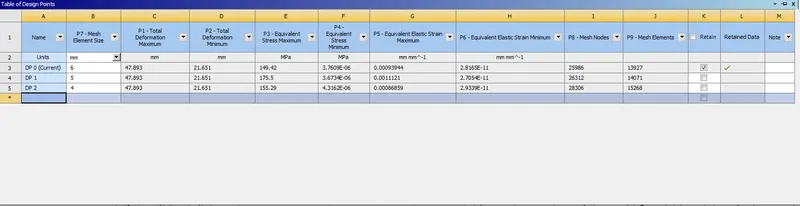
- Below is the tabular result shown in terms of parameter setup for all the three cases
- Below is the tabular result shown in terms of parameter setup for all the three cases
- Conclusion
- We ran a grid dependency test on bevel gear, and based on the above table, we can deduce that by adjusting the global size of the mesh, we gain significantly greater accuracy of the outcome. We can see that as the mesh is refined from 5mm to 4mm, we get a better approximation of the result for equivalent elastic strain and equivalent stress. However, running the simulation with even more mesh refinement would result in a very close approximation of the result with very little change in the result and a significant increase in computational power and time.