Week 2 Railwheel and Track
Railwheel and Track
Introduction to Rail Wheel: A train wheel or rail wheel is a type of wheel specially designed for use on railway tracks.
A rolling component is typically pushed onto an axle and mounted directly on a railway carriage or locomotive, or
Indirectly on a bogie, also called a truck. Wheels are cast or forged and are heat-treated…
Introduction to Rail Wheel:
A train wheel or rail wheel is a type of wheel specially designed for use on railway tracks. A
rolling component is typically pushed onto an axle and mounted directly on a railway
carriage or locomotive, or
Indirectly on a bogie, also called a truck. Wheels are cast or forged and are heat-treated to
have a specific hardness. New wheels are trued, using a lathe, to a specific profile before
being pressed onto an axle. All wheel profiles must be regularly checked to ensure proper
interaction between the wheel and the rail. Incorrectly trued, or worn out wheels can
increase rolling resistance, reduce energy efficiency and may even cause a derailment. A
railroad wheel typically consists of two main parts: the wheel itself, and the tire (or tyre in
British English) around the outside. A rail tire is usually made from steel, and is typically
heated and pushed onto the wheel, where it remains firmly as it shrinks and cools.
Monobloc wheels do not have encircling tires, while resilient rail wheels have a resilient
material, such as rubber, between the wheel and tire.
Rail wheel design can be observed as given below:
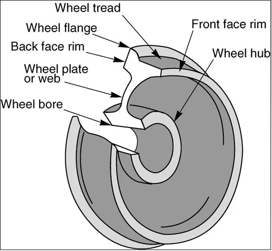
Case 1: Multiply the bearing load by 5 times and compare the results with the load of 100000 N (As done in week 2 video). Compare the Total Deformation, Equivalent stress, and the life under both the loads
procedure for the Railwheel and Track for static structural analysis :
material selection : steel
Geometry:
Static structural:
selection of the step as follows
- Material selection
- Geometry
- Model
- Setup
- Solution
- Result
1) material selection : steel
2) Geometry:
if you want edit some part of the geometry opent the file in space claim :
import from the save folder :
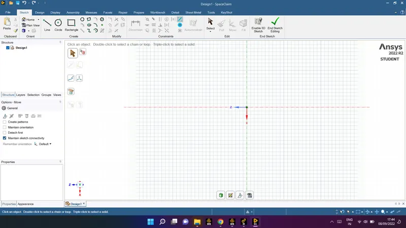
3) Model:
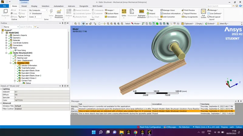
in geomtrey of the model there are 3 parts
as shown bellow:
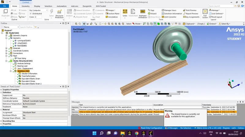
material used for each part is sttructural steel:
* check for the connection :
1) contact
2) joint
in contact :
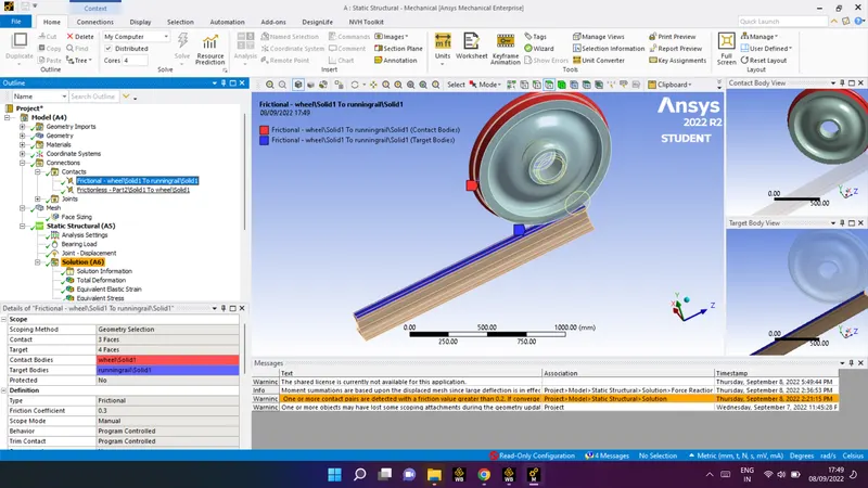
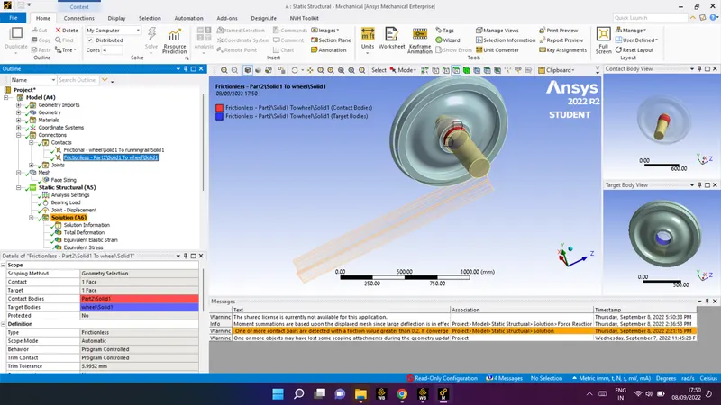
frictional and frictionless
as shown bellow :
fricional: between wheel and track
frictionless:shaft and wheel connection
Joints:
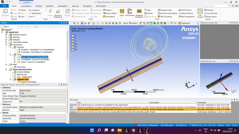
- Fix
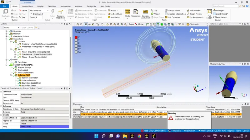
- Translational
- Planer
1) Fix: rail track as fix support
information need to fill in the given condition :
| connection type | body-ground |
| type | fix |
| scope | 2 face |
| behaviour | rigid |
| scoping method | geometry selection |
2) Translational
information need to fill in the given condition :
| connection type | body-ground |
| type | Translational |
| scope | 1 face |
| behaviour | rigid |
| scoping method | geometry selection |
image for the translation :
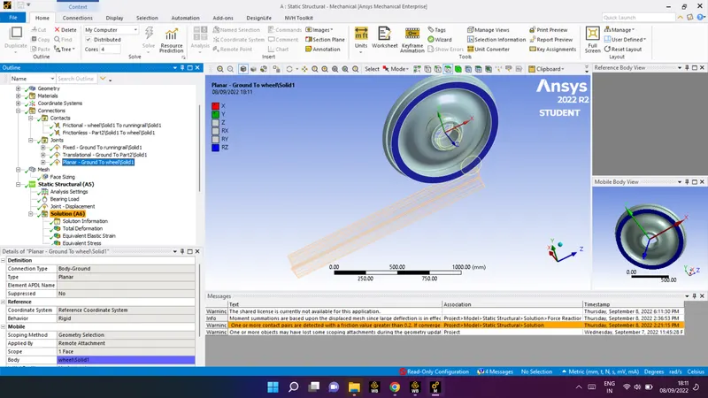
3) Planer:
| connection type | body-ground |
| type | Planer |
| scope | 1 face |
| behaviour | rigid |
| scoping method | geometry selection |
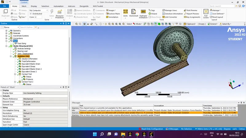
mesh:
face sizing: (select the contacted face on which load is applied ) as shown:
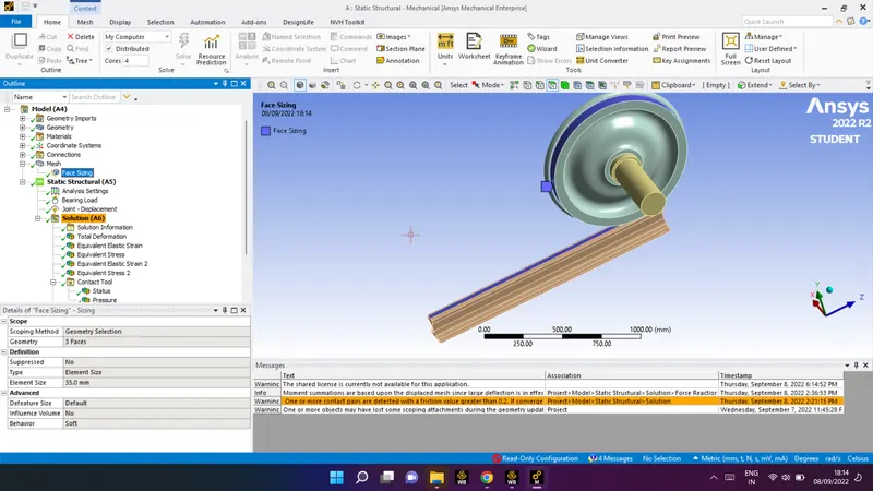
element size: 35 mm
Input for the static structural :
- Bearing load
- joint dispacement
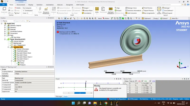
1) Bearing load
| scoping method | geometry selection |
| geometry | 1 face |
| defined by | component |
| coordinated system | globle coordinated system |
| Y component | -5e+005N |
for bearing support as shown:
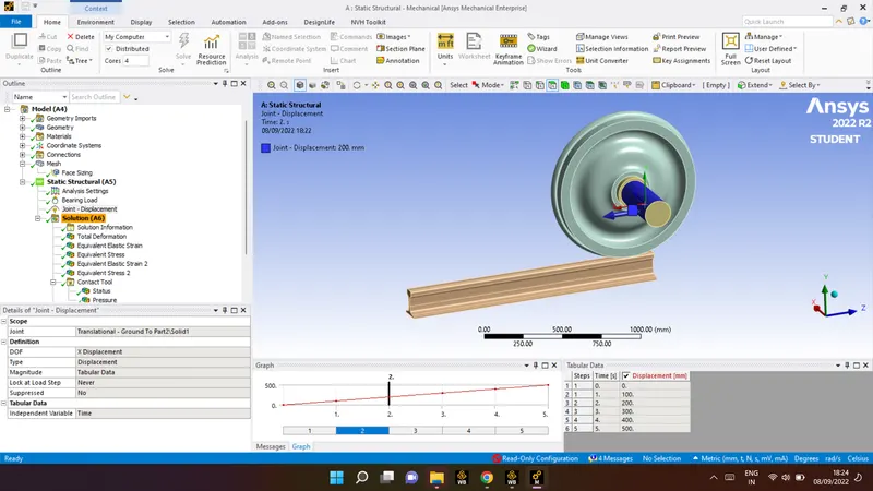
2) joint dispacement :
| joint | ground to part2\solid1 |
| DOF | X Displacement |
| type | Displacement |
| magnitude | tabular Data |
magnitude data:
| step | time | Displacement |
| 1 | 0 | 0 |
| 1 | 1 | 100 |
| 2 | 2 | 200 |
| 3 | 3 | 300 |
| 4 | 4 | 400 |
| 5 | 5 | 500 |
magnitude data:
for the solution :
as per requirement the of case one : insert all through the static solution
- total deformation
- stress
- srain
- contact tool -frictional (pressure)
- force reaction
- user defined Result
- stress2 (for rail whhel only) select by solid selection
- strain2 (for rail whhel only) select by solid selection
- contact tool2 -frictionless (pressure)
now click on solve
Result fot all the condition which we apllied:
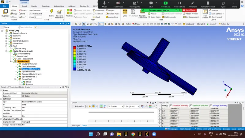
Bearing load :10000N
Equivalent strain:
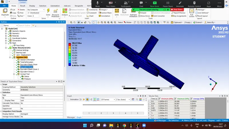
Equivalent stress:
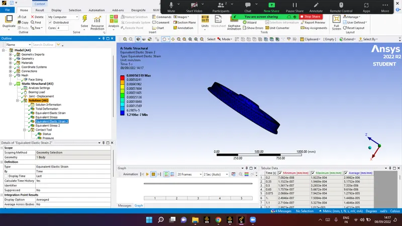
equivalent strain 2: for train wheel
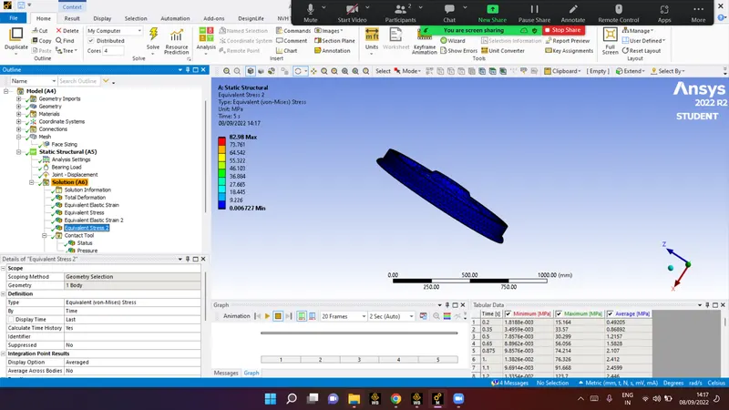
equivalent stress 2: for train wheel
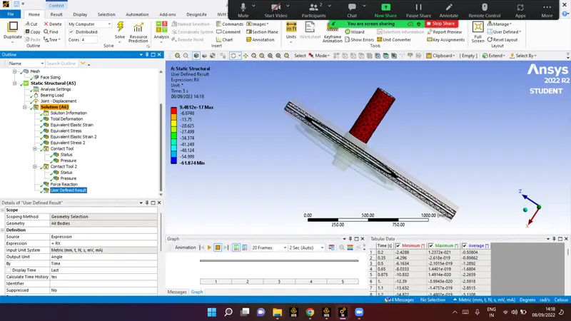
User define result:
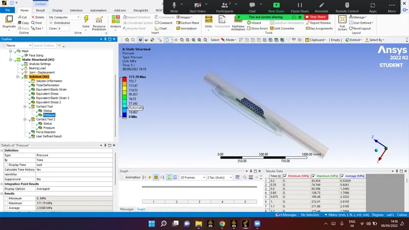
contact tool: pressure value(frictional)
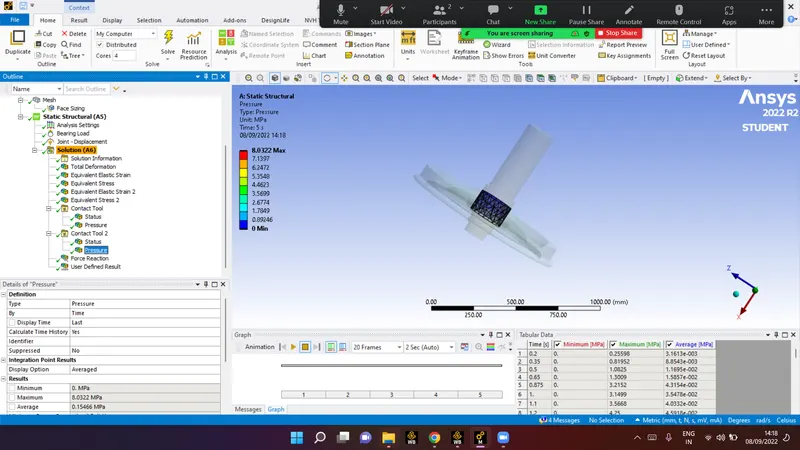
contact tool: pressure value (frictionless)
here the comparison between two apllid force
1) Bearing load
| load | 100000 N | 500000 N |
| total deformation | 14.655mm | 14.676mm |
| stress | 0.28424MPa | 1.408 MPa |
| strain | 1.786e-006 | 8.7561e-006 |
| contact tool | 0.52029MPa | 2.5972MPa |
| force reaction | 23931N | 1.1956e+005N |
| stress2 (for rail whhel only) | 0.49205MPa | 2.4487MPa |
| strain2 (for rail whhel only) | 2.9982e-006 | 1.481e-005 |
| contact tool2 - | 3.1613e-003MPa | 1.9872e-002MPa |
Case 2:
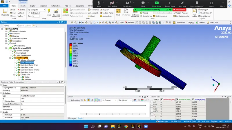
Implement a User-defined result and calculate the Total Deformation from this result and check if it is the same as that obtained by the inbuilt result by ANSYS for a load of 100000 N
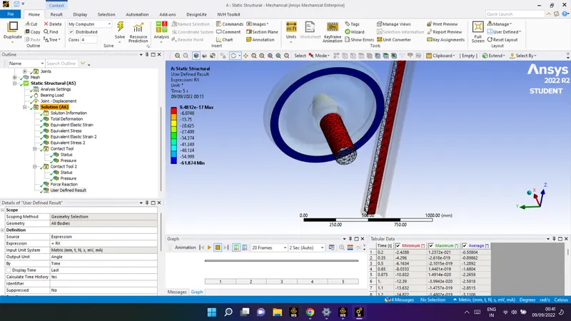
angular in X direction Deformation:
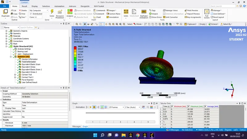
| scoping method | geometrical selection |
| source | Expression |
| Expression | RX |
| Output unit | Angle |
Total deformation:
2) joint dispacement :
| scoping methid | geometry selection |
| source | expression |
| expression | sqrt(UX^2+UZ^2+UY^2)) |
| output unit | length |
Conclusion :
- Static structural analysis on the Railwheel and Track setup is done.
- i have Multiply the bearing load by 5 times and compare the results with the load of 100000 N . Compare the Total Deformation, Equivalent stress, and the life under both the loads is done
- Implement a User-defined result and calculate the Total Deformation from this result it is get the same as that obtained by the inbuilt result by ANSYS for a load of 100000 N.
with this report i have attached zip file for further reference for my analysis
thank you for your time