Week 2 - Flow over a Cylinder.
AIM
To simulate flow over a cylinder and study the phenomenon of Karman vortex street using ANSYS software.
INTORDUCTION
Flow over cylinder is a very important problem in fluid mechanics because of its complex unsteady dynamics of the cylinder wake flow. The laminar vortex shedding , known as Karman Vortex Street takes place at Reynolds numbers greater than 40.
The frequency of vortex can effect the cylinder if this frequency is closer to the structural vibration frequency of the cylindrical body causing resonance.
Hence vortex shedding phenomenon is of great interest in the field of automobiles,computer systems , constructions etc… Understanding the flow behind the cylinder is hence crucial in these industries.
GOVERNING EQUATIONS
- Reynolds number , `Re = (vD)/nu`
Where , `v` is the flow velocity , D is the characteristic length of the geometry and `nu` is the kinematic viscosity of the fluid.
- Drag coefficient , `C_d=(2F_d)/(rhov^2A)`
Where , `F_d` is the drag force , `rho` is the density of the fluid , `v` is the flow velocity and `A` is the cross sectional area.
- Lift coefficient , `C_L=(2F_L)/(rhov^2A)`
Where , `F_L` is the lift force , `rho` is the density of the fluid , `v` is the flow velocity and `A` is the cross sectional area.
- Strouhal number , `Sr = (fL)/v`
Where , `f` is the frequency of the vortex shedding , `L` is the characteristic length
and `v` is the flow velocity.
OBJECTIVE
- To Simulate the flow with steady and unsteady case andcalculate the Strouhal Number for `Re= 100`.
- To calculate the coefficient of drag and lift over a cylinder by setting the Reynolds number to `10,100,1000,10000` & `100000` using steady state solver.
- To study the effect of Reynolds number on the coefficient of drag.
THEORY
Karman vortex street is the phenomenon which takes place behind a bluff body at Reynolds number greater than 40 , at which the wake behind the cylinder becomes unstable. This wake develops a slow oscillation with loss of flow symmetry and vortices are shed from the cylinder surface. The amplitude of the oscillation increase in downstream direction.
This is phenomenon is shown in the diagram given below,
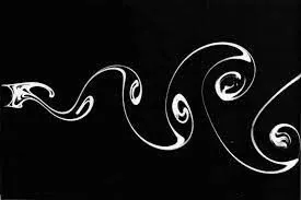
A dimensionless number named Strouhal number(represented by St or Sr) is used to analyze the oscillating unsteady fluid flow dynamics problems. It represents the ratio of inertial forces due to the unsteadiness of the flow or local acceleration to the inertial forces due to changes in velocity from one point to another in the flow field.
PROCEDURE
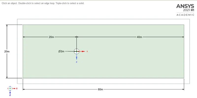
- To set up the geometry space claim software is used. The 2-D geometry created using this software is shown below ,
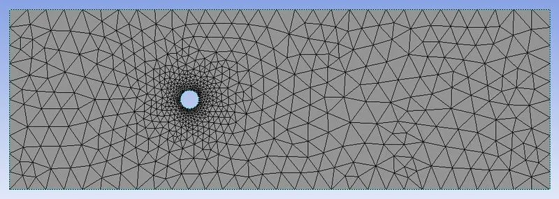
- Next step is to mesh this geometry. This is done using the ANSYS meshing software. The meshing method used is triangles.
- Using edge sizing tool the smoothness of the circle edge is improved by setting number of divisions to 36.
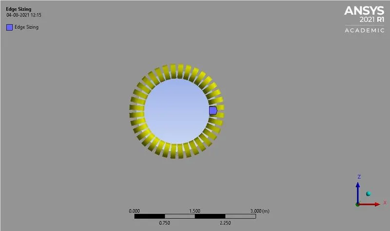
- Also an inflation layer is defined around the circle with 6 layers to create high quality geometry.
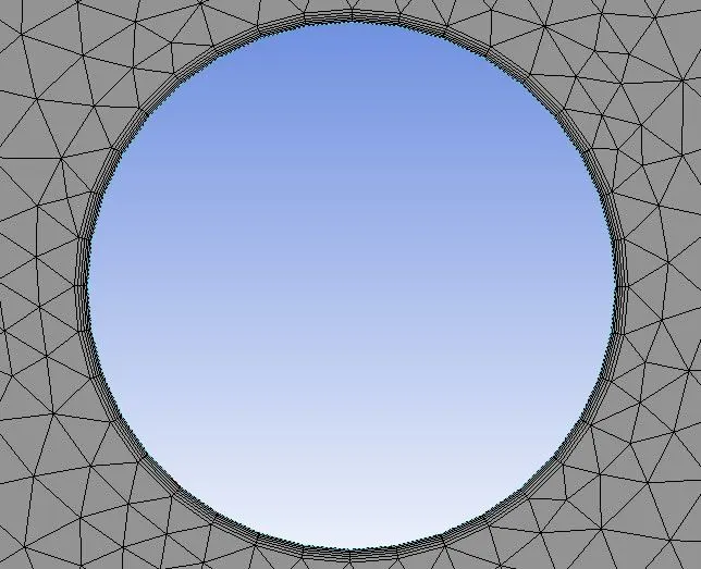
- The refinement of the mesh is done as per the requirement. In this case the element size is set to 0.25m and the number of cells is 40502.
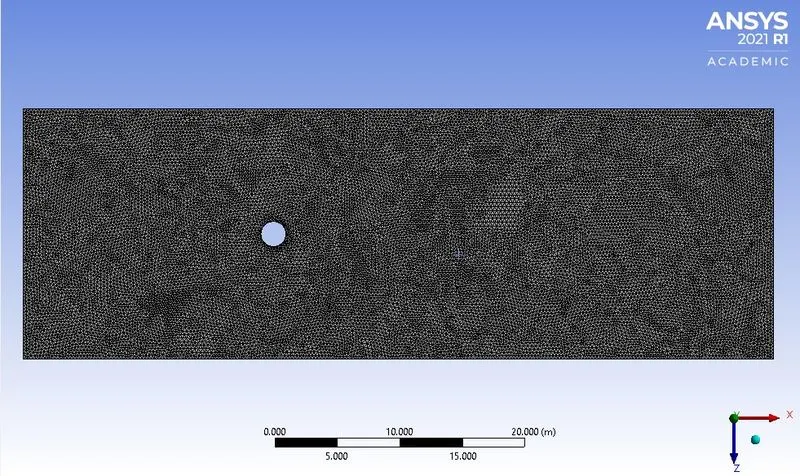
- Then the inlet,outlet, wall and symmetry boundaries are named for this meshed geometry.
SIMULATION SET-UP
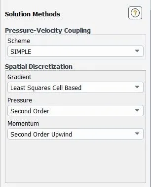
- Solution scheme used is SIMPLE pressure-velocity coupling.
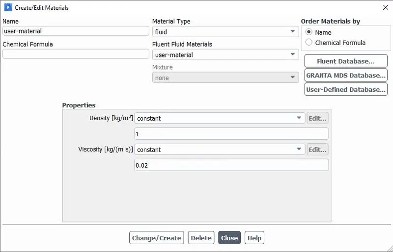
- User defined material is created as shown below,
- Boundary conditions are specified with inlet velocity as 1m/s and pressure as 1atm.
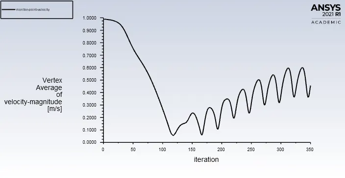
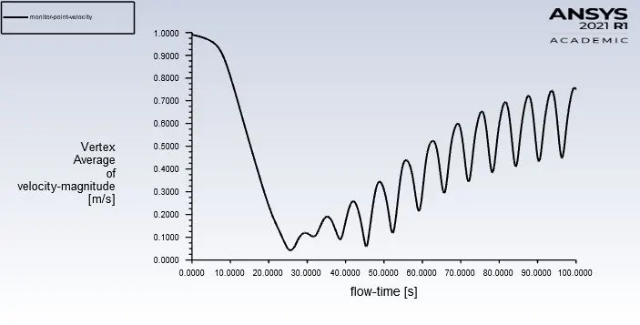
- To analyze the velocity of the flow at the cylinder wake , a monitor point is placed at a distance of 4D (where D is the diameter of the cylinder) from the center of the cylinder.
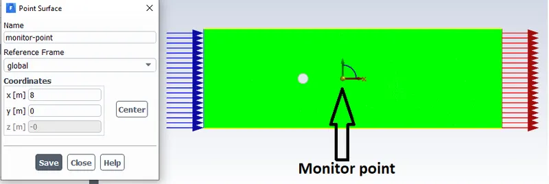
- Then velocity vertex average at this monitor point is calculated.
- Velocity contour is created to visualize the vortex shedding phenomenon. And also an animation of this phenomenon is made.
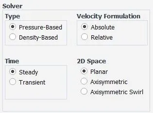
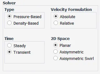
- Pressure based steady state solver is used for steady state simulation and pressure based transient solver is used for unsteady state simulations.
Steady state,
Unsteady state,
TO CALCULATE THE COEFFICIENT OF DRAG AND LIFT
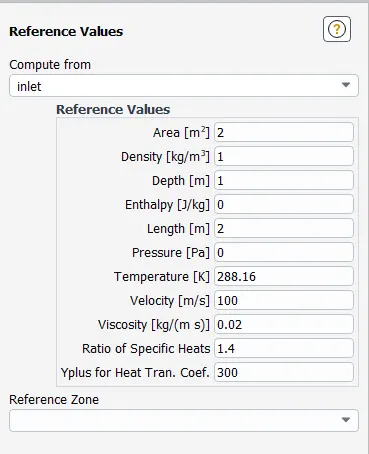
- First of all the reference values has to be set in ANSYS Fluent , this is done as shown below,
- Then under definitions a force report has to be created for drag coefficient and lift coefficient separately. This will give the required plots.
TO CALCULATE THE STROUHAL NUMBER
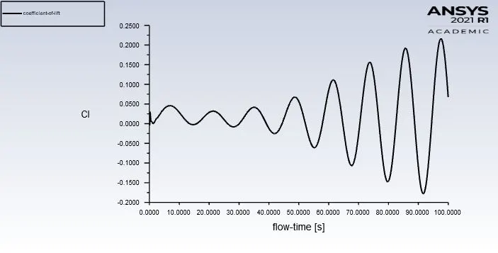
- The strouhal number is calculated by using the unsteady simulation results. The coefficient of lift values at each time step is required for that.
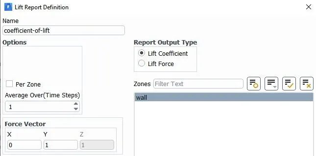
- The coefficient of lift value is calculated by defining a force report for lift coefficient at wall as shown below ,
- The FFT (Fast Fourier Transform) is used to find the strouhal number , which will convert the time dependent value of lift coefficient to frequency domain. On the X-axis magnitude is selected and on the Y-axis Strouhal number. Then the already calculated values of lift coefficient is loaded as the input. This set-up is shown below,
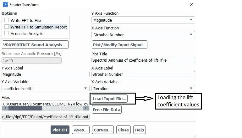
- From the output results of the FFT file , the required Strouhal number will be the one with the highest magnitude value corresponding to it.
TO CHANGE REYNOLDS NUMBER
- As the values of diameter of the cylinder and kinematic viscosity of the fluid are kept constant , the velocity of the flow at the inlet has to be varied in order to get the required Reynolds number value.
- This calculation is done as,
`Re = (vD)/nu`
Where , `D = 2m` and `nu =0.02 m^2/s`
So to get , `Re =10` , the velocity value has to be `0.1m/s`.
Similarly other required values of Reynolds number can be attained by changing the velocity value accordingly.
RESULTS
STEADY STATE SIMULATION (at Re=100)
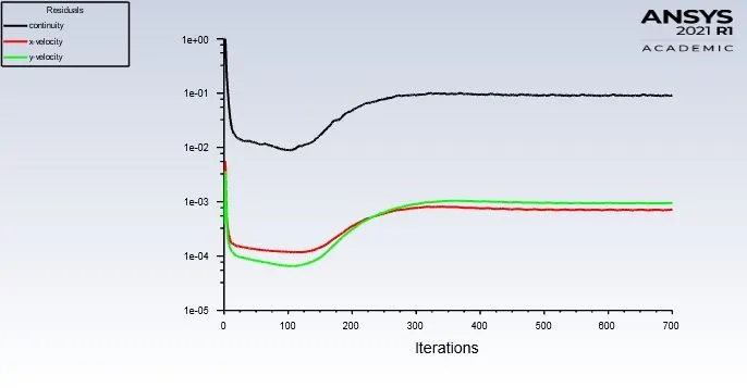
Convergence plot,
Vertex average velocity at the monitor point ,
UNSTEADY STATE SIMULATION (at Re=100)
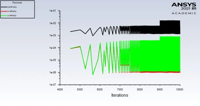
Convergence plot,
Vertex average velocity at the monitor point ,
Coefficient of lift value,
Strouhal number,
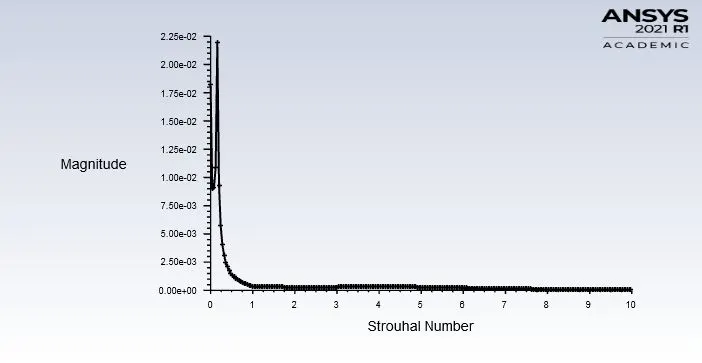
The Strouhal number was found out from this graph as , `Sr=0.1597`
COEFFICIENT OF DRAG(`C_d`) AND LIFT(`C_L`) PLOTS AND VALUES (Using steady state solver)
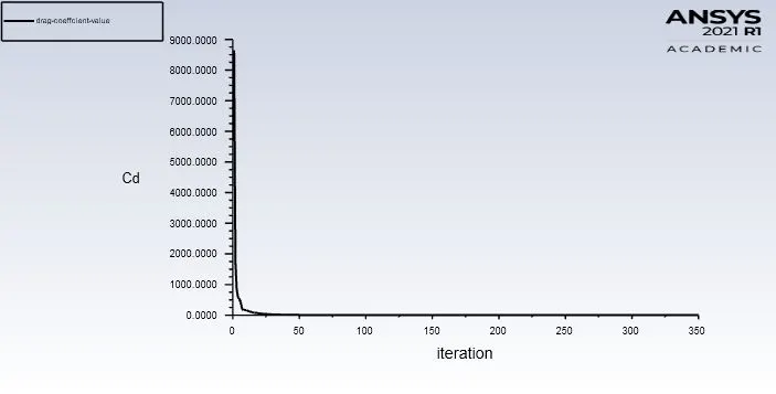
`C_d` at `Re=10`,
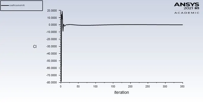
`C_L` at `Re = 10`,
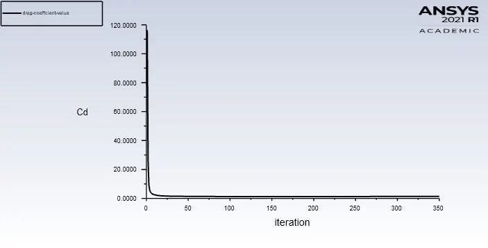
`C_d` at `Re=100`,
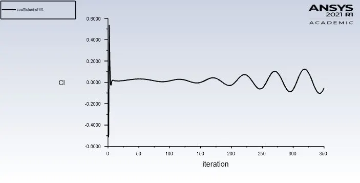
`C_L` at `Re = 100`,
`C_d` at `Re=1000`,
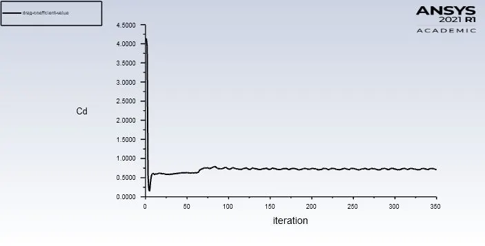
`C_L` at `Re = 1000`,
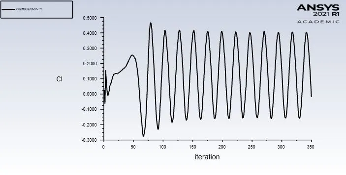
`C_d` at `Re=10000`,
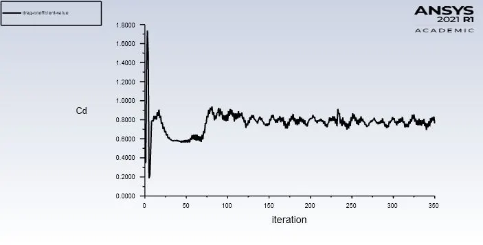
`C_L` at `Re = 10000`,
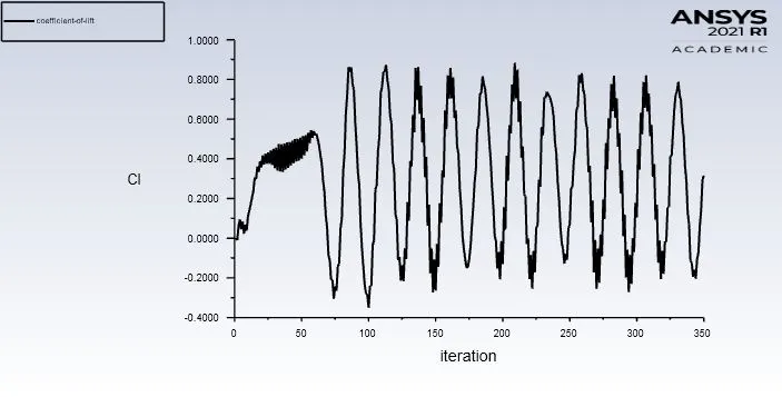
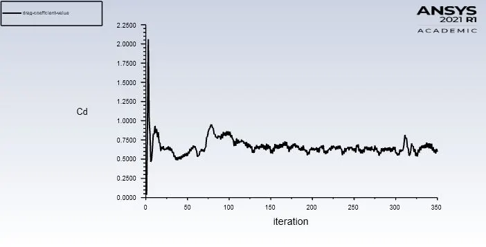
`C_d` at `Re=100000`,
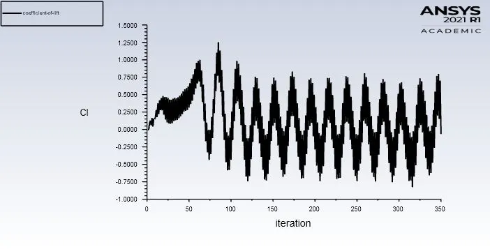
`C_L` at `Re = 100000`,
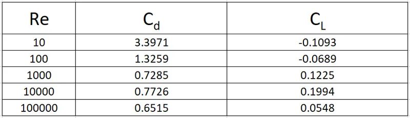
The values of `C_d` and `C_L` are tabulated below,
VORTEX SHEDDING ANIMATION
https://drive.google.com/file/d/1FYE-EiqWHQjmqxQTdIF-1KC7ilT9ZbEK/view?usp=sharing
CONCLUSION
The simulation over a cylinder to study the phenomenon of Karman vortex street has been done successfully using ANSYS software.
The Karman vortex street has been visualized and variation of velocity studied at the wake after the cylinder. Also the simulations have attained convergence for both steady state and unsteady state and this has been confirmed using the residual values plot.
The following conclusions has been made from the simulation results.
From the table with `C_d` and `C_L` values at different Reynolds number it is clear that the Reynolds number is inversely proportional to coefficient of drag value , i.e as the Reynolds number increases the value of drag coefficient decreases. This can be also verified from the formulas of the both , where Reynolds number formula is directly proportional to the velocity and drag coefficient formula is inversely proportional to the velocity value.
The coefficient of drag value at `Re =100` is verified by referring to a research paper on “Numerical simulation of laminar flow past a circular cylinder (1)”.
In the journal the value of `C_d` at `Re=100` for Two-dimensional simulation is `1.3353` .
On comparing this value with the calculated value of `1.3259` , the absolute error is found out to be `0.7%` and hence the simulation results are validated with accuracy.
REFERENCE
(1) N. Rajani , A. Kandasamy , Sekhar Majumdar , Numerical simulation of laminar flow past a circular cylinder , 2008.