Week 2 - Flow over a Cylinder.
FLOW OVER CYLINDER
AIM=
simulate the flow over a cylinder and explain the phenomenon of a vertax street under standing the vortex sheeding for diffrent reynolds number by changing the inlet velocity accordnally .
create a monitor point behind the cylinder at the distance 4 times the dia meter which can be used to calculkate and analyze the vortex sheeding
OBJECTIVE
1. simulate the flow with the steady and unsteady case calculate the strouhal numer for Re=100.
2. calculate the co efficent of drag and lift over a cylinder by setting reynolds number to 10,100,1000,10000,100000 (run with a steady solver).
3. in both apporaches show that the flow has converged that is what quantities or plot need to be looked at to determine that the flow has converged.
4. plots of the cofficent of drag li8ft
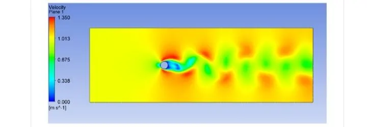
5. plot to show vortex sheeding behind the cylinder
6.mentain the preferred material at the end of the chalange
THEORY
FLOW OVER CYLINDER
in split of extensive experimental and numerical studies of almost over a century, flow around the circular cylinder still remain a challange problem in fluid mechanics .where as intenstive are calculated even today to undrstand complex unsteady dynamics of the cylinder and associated problem of heat and mass transfer are encountered in a wide velocity of engg application .
both experimental meseurment and numerical computational have con formed the onset iniutally of the wake flow behind a cylinder beyond a critical reyonlds number liding finally to kind of peroiodic flow identify by case of liminer flow past cylinder with regular ploygonal cross section ,the flow usally sepatre at one or more sharp corner of cross setion the geomtry bitself forming a system of velocity in the wake on either side of the mid symmetry plane.
2. STROUHAL NUMBER
the strouhal numer is
`St=fD/U'
WHERE F= frequency of vortex sheeding
D= charectrisitic diameter of the cylinder
U'=fluid flow of velocity
geomtry creation
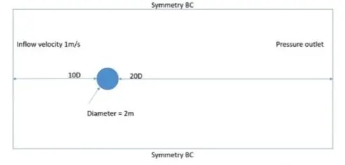
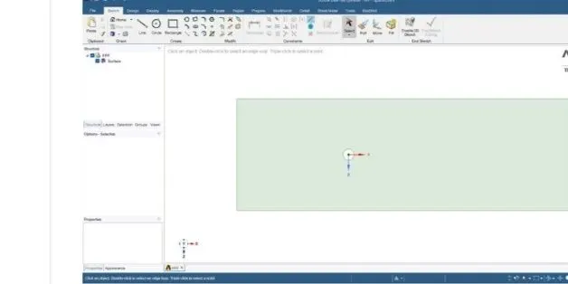
the 2d geometry is created by using the above diamension then the inside cylinder is deletrd order to carry out the simulation
MESH GENERATION
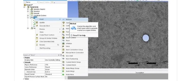
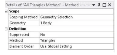
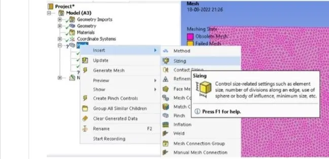
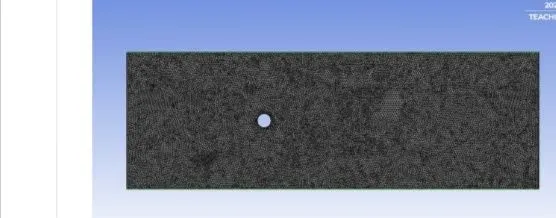
to change the meshing method go to mesg >insert>method>select face >method triangle >generate mesh
SIZING
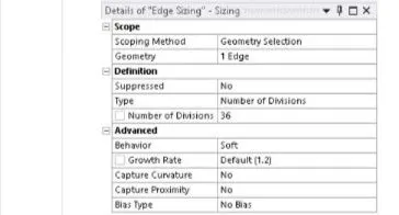
go to the mesh >insert>sizing >select edze>type no of division >enter 36>and generate mesh
INFLATION
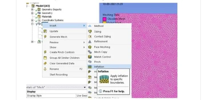
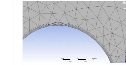
to create a infation layer go to mesh >insert>inflation>select face>select edge >number of layer>enter the number of generate mesh
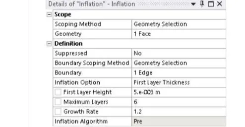
6 layer inflation
PART 1
REYNOLDS NUMBER
for Re=100
Re=`U.p.D/u`
FLUENT STEP
SETUP STEADY STEP UNSTEADY STEP
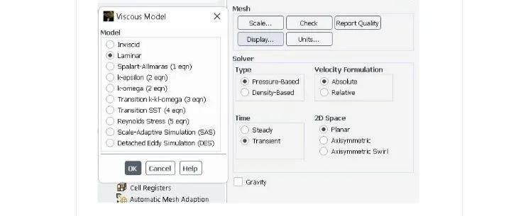
SLOVER TYPE pressure based pressure based
VELOCTY FORMILATION absolue absolute
TIME steady leminar
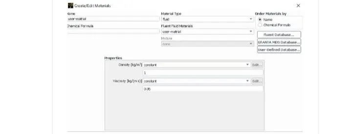
METRIAL user material user material
CELL ZONE fluid type user material fluid use material
desity-1kg/m3 desity-1kg/m3
dynamic viscocity-0.02kg/ms dynamic visocity-0.002kg
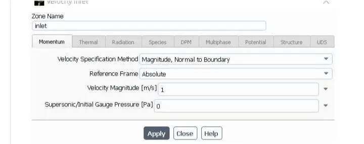
.inlet (velocity inlet) . inlet (velocity inlet)
velocity magnitude 1m/s velocity magnitude1m/s
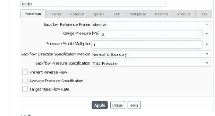
. outlet(pressure outlet ) .outlet(pressure outlet)
BOUNDARIES gause pressure-0pa gauge pressue-0pa
.symmetry-symmetry .summetry-symmetry
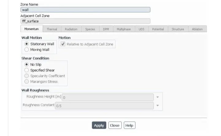
.wall-stationary wall .walls-statiotanary wall
condition-no slip condition -no slip
steady state
material
CELL ZONE
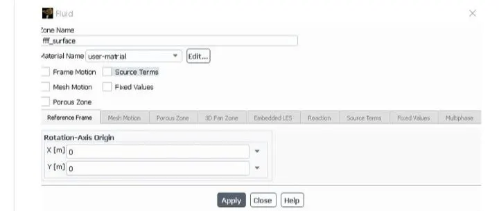
BOUNDARIES
INLET
OUTLET
WALS
SOLUTION
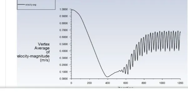
.vortex average of velocity magnitude using surface report at a monitor point at 10 m from the center of the cylinder to the right of the cylinder along the X-direction
. coefficent pf drag anfd co efficent of lift report are created using face report
INITIALIZATION= hybrid for steady state
the standerd of unsteady state
ACTIVITES=CONTOUR PLOT OF PRESSURE AND VELOCITY AND SOLUTION ANIMATION ARE CREATED AFTER INITIALIZE THE SOLUTION
run calculation
for steady -state -no of itteration=500
for transient state -time step ==0.1
no of itteration =500
RESULT
STEADY-STATE solver Re=100
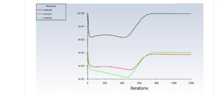
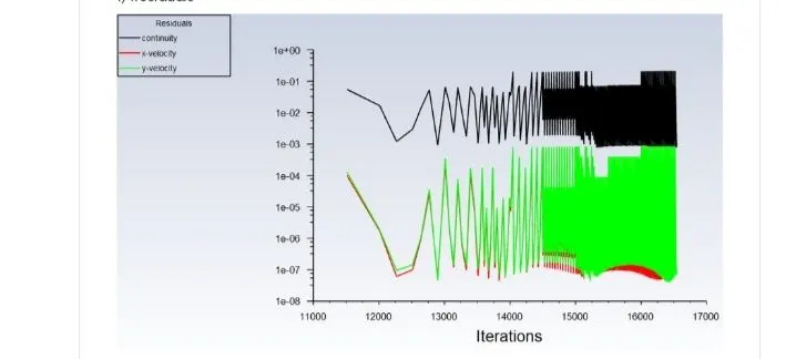
RESIDUAL
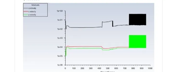
the plothelp in monitering the change in each and every consevance criterion for every time step and plot those value for every itteration or time step .the plot helps to know when converged is achived
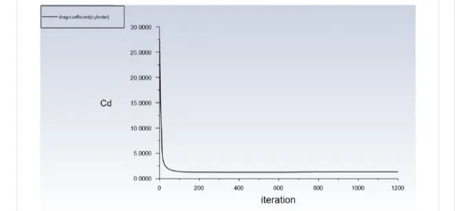
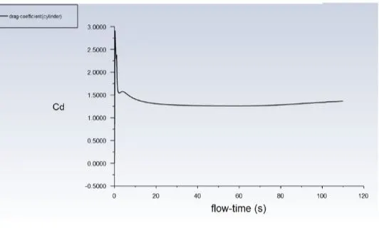
co efficent of drag
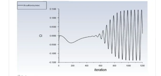
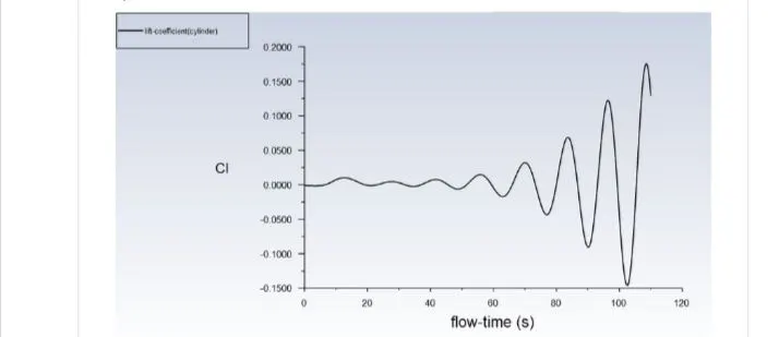
co efficent of lift
vortex average
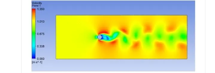
velocity countour
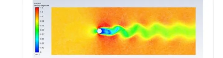
result -unsteady state solver with simple pressure velocity coupling
residual
co efficent of drag
co efficent of lift
vortex average
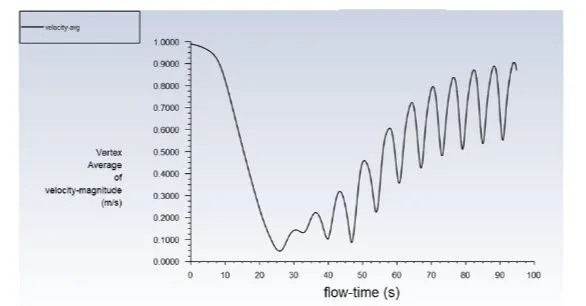
velocity countour
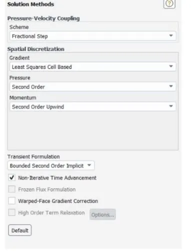
result -unstady state solver with nta solver
residual
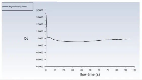
coefficent of drag
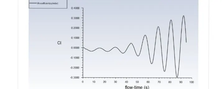
coffient of lift
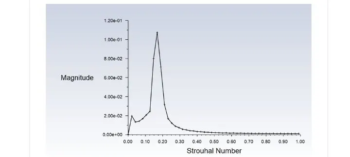
strouhal number
the sstrahul number is calcilated by going into plot option in fluent in which fft option has closed in ftt option y axis function should be magnitude ans x axis function should be strahoul number
CONCLUSION
After running the simulatio respectively for steady state and unsteady state simulation was found that unsteady simulation provide the result near to be experimental value
SOLVER COEFFICENT OF DRAG COEFFICENT OF LIFT TIME TAKEN
STEADY STATE SOLVER 1.48 0.05 7MIN 23 SEC
UNSTEADY STATE 1.31 0.48 21 MIN
(SIMPLE METHOD)
UNSTEADY STATE SOLVER 1.43 0.06 13 MIN
case-2 simulation over cylindr with steady solver for reyolds number of
10,100,1000,10000,100000
velocity of plot
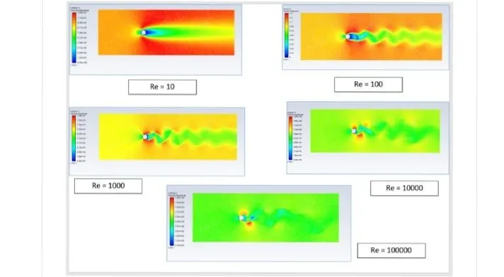
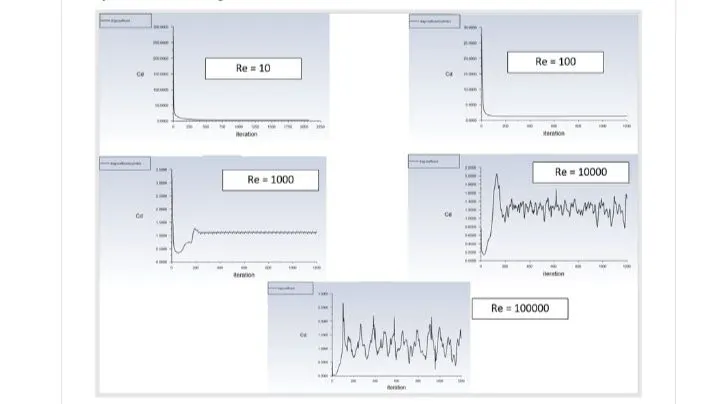
co efficent of drag
cofficent of lift
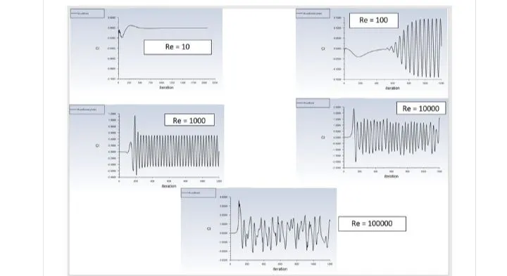
comperision table of reynolds number with co efficent of drag and lift
reynolds number co efficent of drag coeffiecent of lift
10 3.37 0.0011
100 1.31 0.048
1000 1.08 0.433
10000 1.18 0.56
100000 0.85 0.672
from above the plot we cansay that the volume of lift coefficent it keeps on increasing as keep incresing the velocity and reynolds number
CONCLUSION
.WHEN FLUID OVER FLOW OVER THE CYLINDER,THE WAKE RESION OF FORMED NEXT TO THE CYLINDER DUE TO DECREASE IN PRESSURE AND RECALCULATION OF FLOW OCCERS HENCE FLOW SEPRATION