Week 2 - Flow over a Cylinder.
week 2 challenge:
aim:
Simulate the flow over a cylinder and explain the phenomenon of Karman vortex street.
PART-I
- Simulate the flow with the steady and unsteady case and calculate the Strouhal Number for Re= 100.
PART-II
- Calculate the coefficient of drag and lift over a cylinder by setting the Reynolds number to 10,100,1000,10000 & 100000. (Run with steady solver)
- Discuss the effect of Reynolds number on the coefficient of drag. [ Results should be validated with any standard literature and error should be within 5 %]
to find:
- In both approaches, show that the flow has converged. That is, what quantities or plots need to be looked at to determine that the flow has converged?
- Plots of the coefficient of drag and lift.
- Plots to show vortex shedding behind the cylinder.
- Mention the referred material (Reference Paper or Fluid Mechanics Textbook) at the end of the challenge submission page.
introduction:
In matematics,potential flow around a circular cylinder is a classical solution for the flow of an inviscid, incompressible fluid around a cylinder that is transverse to the flow. Far from the cylinder, the flow is unidirectional and uniform. The flow has no vorticity and thus the velocity field is irrotational and can be modeled as a potential flow . Unlike a real fluid, this solution indicates a net zero drag on the body, a result known as d'alemberts paradox
Flow over a cylinder is a classical problem for understanding the flow over an obstacle. The geometry of the cylinder is simple and allows us to understand all the complexities that occur and turbulence for different Reynolds Numbers. Reynolds Number helps us to understand the flow patterns of the different fluid flow situations. The different range of Reynolds Numbers represents different flow patterns. At low Reynolds Numbers, the flow pattern is observed to be Laminar i.e., Smooth, Constant fluid motion. At higher Reynolds Numbers the flow pattern is observed to be Turbulent i.e., Chaotic eddies, Vortices, and Flow instabilities. In this project, we will try to understand the variation of velocity and pressure in certain flow directions for different Reynolds Numbers by simulating it with proper boundary conditions, Mesh sizing, Convergence criteria using SolidWorks Flow Simulation.
solving and modelling:
- Step 1 : Pre-processing/Geometry Creation
- Launch Ansys workbench.
- Open space claim. draw a circle with 2m and rectangle with the centre of 20m toleft and 40m to left and top and bottom with the axis with 10m respectively.
- As the given geometry is solid we need to perform enclosure.
- Click on 'enclosure' tab and select 'select face' option. Select faces and draw enclosure. then with pull tool draw the model.
- Suppres the circle for physics. Close Space Claim.
- Update the project.
-
A plate with the dimension of 20*60m is created using spaceclaim.
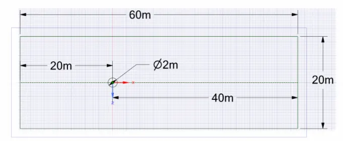
Now,we want to simulate effect of fluid flow over cylinder, select the circle and delete it.
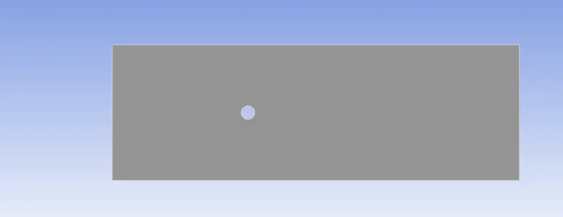
Figure of geometry.
- Step 2 : Mesh Generation
- Open mesh generator in ansys fluent.
- Selec the faces and name the each face accordingly as inlet (in x and y direction respectively), outlet and wall.
- Generate the default mesh.
- Edit the element size to 2 m and update the mesh.
- Once the mesh is genertaed, close the mesh generator and update the project.
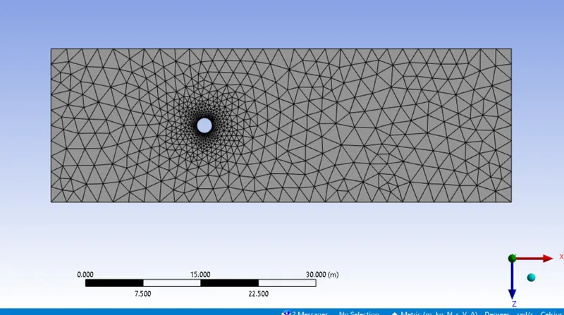
Figure of generated mesh.
3.After generating mesh,it is seen that size of cirle looks distoreted.
go to mesh > sizing > select circular edge > deffinition >type > no,of divisions >36.
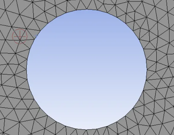
4.To capture better results near cylinder wall, go to mesh > inflation > select the body and edge > inflation option : 1st layer thickness >1 st layer height :5e-3 m >maximum layer :6

Solving :
1. select laminar flow inside the viscous model.
2.As we wanted to customimize material property for simulation, go to materials > fluent database > select the material (air) > copy it> rename the name of material.
- Step 3 : Solution Setup
- Open setup in fluent. The mesh and geometry will be generted. If it doesn't generate then go back to mesh generator and edit accordingly.
- Click on check mesh button. If the console doesn't show any warning then the mesh is fine.
- Click on Physics option and select pressure based solver, time as steady, velocity formulation as absolute and clickon Energy button as we need to solve the energy equation.
- In turbulence model select viscous k-epsilon realizable model.
- Click on solution and input the inlet data for each individual case. Outlet and wall conditions are already setup by fluent solver.
- Click on definitions and selected Area weighted Average and standard deviation for temperature at the outlet.
- Click on initialiaze button as the console will run calculation for 10 iterations.
- Click on Run calculation and set the number of iterations for 250 and hit the calculate button.
Inlet Conditions of the cases to be run :
- inlet velocity of 1m/s, temperature of 300k.
Plots :
chapter1:
- viscosity of 0.05
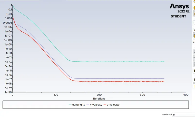
Figure shows plot of residuals versus number of iterations for Case 1.
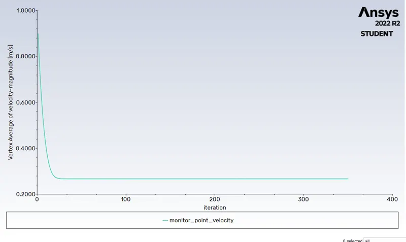
Figure shows plot of Area -Weighted Average of Temperature versus number of iterations for case 1
velocity:
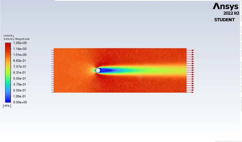
here it shows the velocity flow over a cylinder,
Velocity is the prime indicator of the position as well as the rapidity of the object. It can be defined as the distance covered by an object in unit time. Velocity can be defined as the displacement of the object in unit time.
in simple words, velocity is the speed at which something moves in a particular direction. For example as the speed of a car travelling north on a highway, or the speed a rocket travels after launching. The scalar means the absolute value magnitude of the velocity vector is always be the speed of the motion.
pressure :
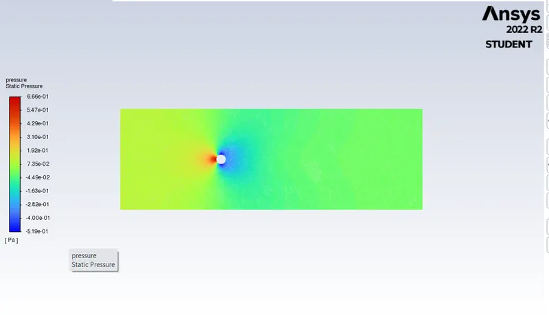
here it shows the drag pressure force created on the flow of cylinder.
Pressure is the force applied perpendicular to the surface of an object per unit area over which that force is distributed. Gauge pressure is the pressure relative to the ambient pressure. Various units are used to express pressure.The SI unit of pressure is pascal (represented as Pa) which is equal to one newton per square metre (N/m2 or kg m-1s-2).
element size:
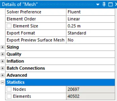
from the above table the element nodes are about 20697 and its elements are 40502.
Conclusion:
1.When fluid flows over cylinder, wake region is formed next to cylinder due to decrease in pressure and recirculation of flow occures and hence flow separation occures.
2.As flow over cylinder is being transient meaning time dependent phenomenon, we are unable to observe flow separation at low reynolds no.(say 50).
3.In this assignment we have kept all parameters constant and have only varried velocity to change reynolds number. So as the reynolds no. increases coefficient of drag decreases.however after reynolds no. = 4000, flow is turbulent and hence coefficient of drag is lower.
4.Strauhal no. calculated for unsteady state with reynolds no.= 100 is 0.112.
Numerical simulation of laminar flow past a circular cylinder:
in the reserach paper, it is shown about the 2d and 3d flow over a cylinder in different laminar regimes.
pressure based finite volume method with time accurate computational of incompressible fluid of second order convective flux discretization is used.
the fluid is cross flowed normal to the axis of the stationary circular cylider and associated heat and mass transfer.
In fluid dynamics, a Kármán vortex street is a repeating pattern of swirling vortices, caused by a process known as vortex shedding, which is responsible for the unsteady separation of flow of a fluid around blunt bodies.
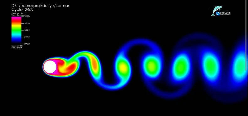
karman vortex street
in case of streamline flow past cylinder.
reynolds number(re)=UD/v, where U is free stream velocity, D is the linear dimension, v is the viscosity.
A flow of liquid is said be a streamline flow if its Reynold number is less than 1000 (or 2000) whereas the flow having Reynold number greater than 4000, is known as turbulent flow.
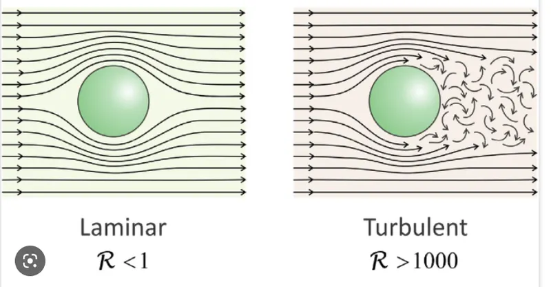
characteristic regime of flow past a circular cylinder:
zdravkoich, in his excellent monograph explains the following.
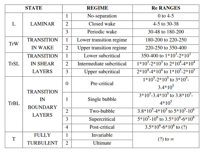
since 1938, he collected al the experimental, analytical and numerical computation data on a flow past a cylinder and he classified it into 5 different flow regimes based on its reynolds number. it shown in the below fig.
all the computation are done by using pressure based finite volume Navier stokes algorithm(RANDs3d) for time prediction of flow
results:
in case of L1 and L2 regime, where the flow is steady the present computation are limited to 2d flow only.
L3 regime of periodic vortex sheding for re upto 200, the flow structure in the periodic wake vortex.
computaion upto re200 are therfore 2d flow and it is compared with measurement data reported in the literature of strouhal frequency( Strouhal number, abbreviated as Sr, a dimensionless number, is used to describe oscillating flow. It is used in fluid dynamics and is the ratio of inertial forces due to the unsteadiness of the flow or acceleration of inertial forces due to the changes in velocity between points in a flow field.), circumferential time avreage surface pressure and skin friction and the RMS values of lift and drag co efficient.
beyond, the critical re of 180-200, the easurement as well as numerical simulate data demonstrate a suspect of the 2d wake behind a cylinder to 3d floquent instablity
conclusion:
upto re 200,the 2d computational results agree resonably well with the accurate measurement data for the strouhal number,the base pressure coefficient and the mean drag coefficient.
however , beyond the critical re 180 , gross discreoancies have been observed between 2d result and measured data.
The computed spanwise and streamwise vorticity component contours viewed on different cartesian planes indicate that the wake structure for re>180 Re>250"> is less regular with less alignment and shorter wavelength of the streamwise vortices.
The prediction of the frequency and amplitude of the fluctuating forces on the cylinder at re=300Re=300"> using the present Navier–Stokes solver is also found to be reasonably accurate.
Computations are in progress using larger domain and finer resolution along the spanwise direction in order to have a better understanding of the physics of the transition process in the cylinder wake.
referance:
https://www.sciencedirect.com/science/article/pii/S0307904X08000243
https://www.youtube.com/watch?v=IDeGDFZSYo8
https://www.piping-designer.com/index.php/properties/dimensionless-numbers/177-strouhal-number