Week 2 - Flow over a Cylinder.
Aim –
Simulate the flow over a cylinder and explain the phenomenon of Karman vortex street.
PART-I
- Simulate the flow with the steady and unsteady case and calculate the Strouhal Number for Re= 100.
PART-II
- Calculate the coefficient of drag and lift over a cylinder by setting the Reynolds number to 10,100,1000,10000 & 100000. (Run with steady solver)
- Discuss the effect of Reynolds number on the coefficient of drag. [ Results should be validated with any standard literature and error should be within 5 %]
Tools used :-
- Space claim - Circle, line,surface
- Ansys meshing - Sizing , Inflation
- Ansys Fluent - Turbulence model, Material , Boundary condition, Reference value , Initialisation, Calculate
- Cfd post - Plane , Velocity contour , pressure contour
Procedure :-
Geometry creation
- Open workbench
- Open spaceclaim for geometry creation
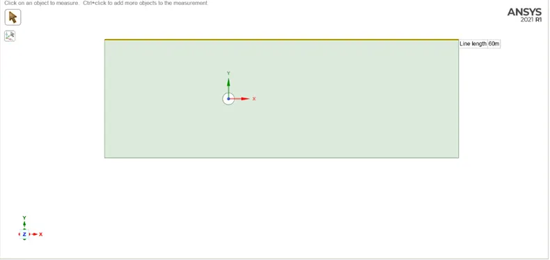
- Draw circle of diameter 2m using circle option which is wall of cylinder
- Create domain of dimension 60m ´ 20m around circle
- For creating surface click on 3d view
- Delete the circle surface which will act as cylinder
Mesh Generation
- Open Ansys mesh
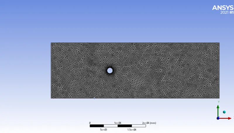
- Select all triangle method from method option
- Give element size of 500 mm
- For creating boundary layer refine circle edge by giving separate edge sizing length
- Now click on inflation layer and create 5 layers with transition rate of 1.2
- To generate mesh click on Generate option
Solving
- To solve the given problem we need to transfer, generated mesh to Solver
- Open Ansys fluent
- Select the turbulence model, as simulation has to be done on Reynolds number below 2´105 so flow will be laminar and for that laminar turbulence model to be selected
- In material selection, Air will be the fluid with density 1
- Simulation has to be done on different Reynolds number ranging from 10, 100,1000,10000 to 100000 so based on given Reynolds number velocity will change.
So, boundary condition will be given as
|
Reynolds Number |
Inlet velocity |
|
10 |
0.25 |
|
100 |
2.5 |
|
1000 |
25 |
|
10000 |
250 |
|
100000 |
2500 |
Outlet – pressure outlet
- Give reference value from inlet condition and Area- 2m2 , length- 2m
- Create report definition for Cl , Cd , also we need to find vertex shedding so create Average vertex velocity.
- Initialize the simulation with standard initialization
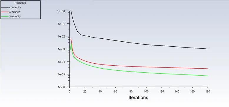
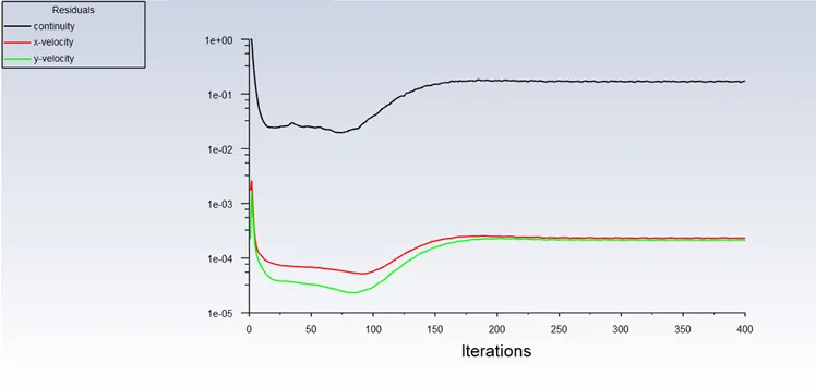
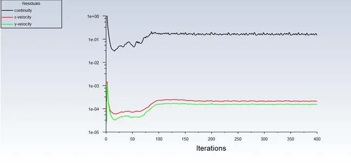
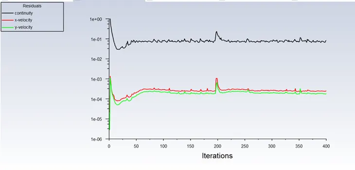
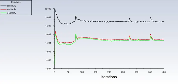
- There has to be separate simulation for each Reynolds number, so iterate each simulation for 400 times.
- After iteration when solution gets converged, we get solution
Post processing
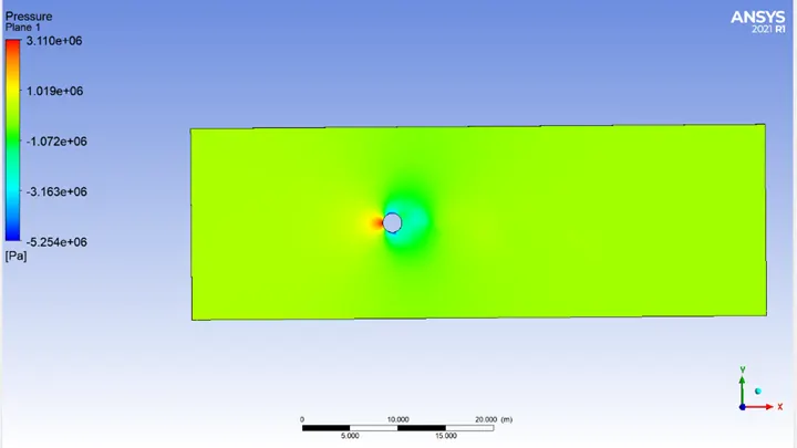
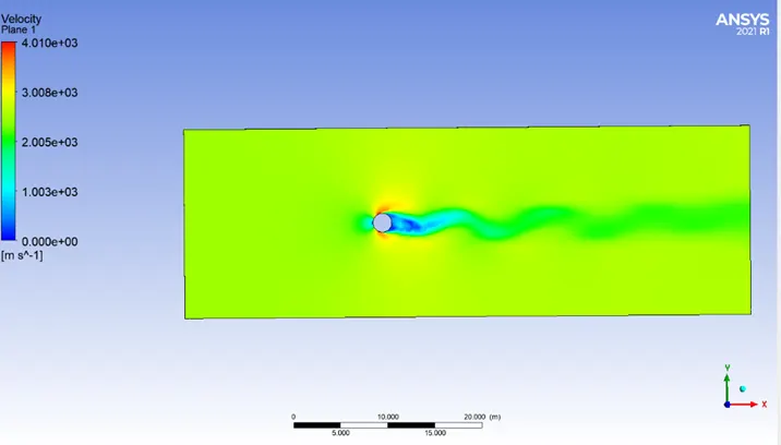
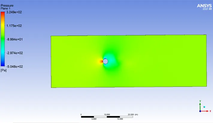
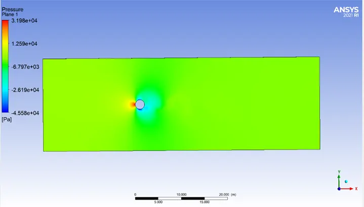
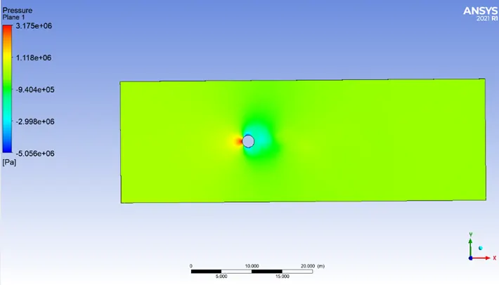
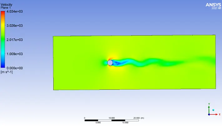
- Create velocity and pressure contour for each simulation
- Validate the result from literatures experimental results
Result
Karman vortex street
A repeating pattern of swirling vorticities surrounded by irrotational fluid, these vorticities arranged in parallel rows in opposite pattern of rotation and these patterns are called Karman vortex street. These Vortex street causes unsteady separation of fluid around blunt bodies. Vortex street can damage wide range of structures. So for engineers it is a challenge to monitor and reduce the damages produced by vortex shedding.
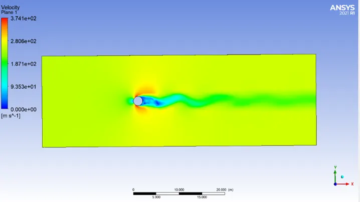
From the literature reviews, it has been found that when Re ~ 10 a pair of eddies formed behind the blunt bodies such as cylinder and when Re~100 eddies start to separate off from the bodies and karman vortex street formed. So it can be observed that as Reynolds number is increasing, strength of vortex street also increases.
Here, simulation is done at various Reynolds number starting from 10, 100 , 1000 , 10000 , 100000, At these Reynolds numbers , vortex street appeared and as Reynolds number increases ,Vortex street becomes more visible.
Part 1
Strouhal Number
Strouhal number is a dimensionless number which tells oscillating behaviour of fluid flow. It is a measure of ratio of local acceleration to the inertial forces due to changes in velocity from one point to another in the flow field.
`St=(fL)/U`
Where, f – frequency of vortex shedding
L- Characteristics length
U- Flow velocity
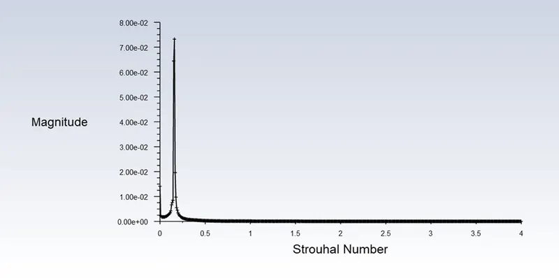
Here, To calculate Strouhal number, simulation has been done at Re-100 for steady and transient state condition.
Maximum Strouhal number at steady state is 0.4
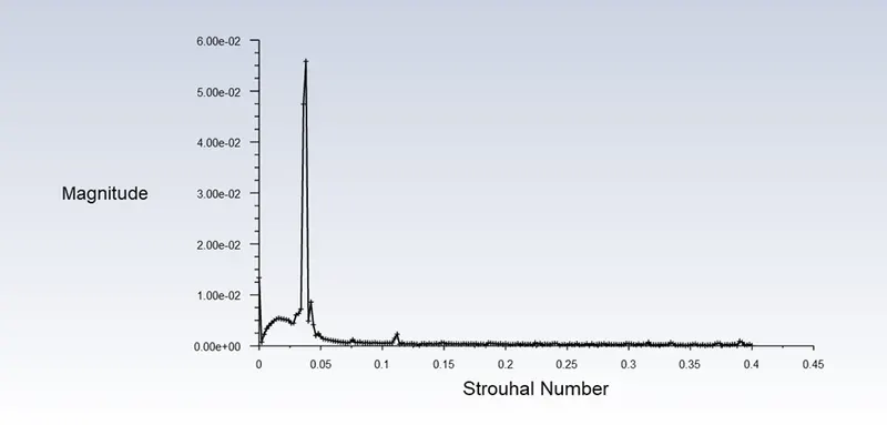
Maximum Strouhal number at transient state is 3.996
Part 2
1) Convergence plot, pressure contour and velocity contour at different Reynolds number
Reynolds number - 10
Convergence plot
Pressure contour
Velocity conotur
Reynolds number - 100
Convergence plot
Pressure contour
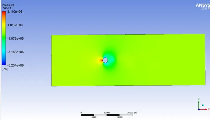
Velocity contour
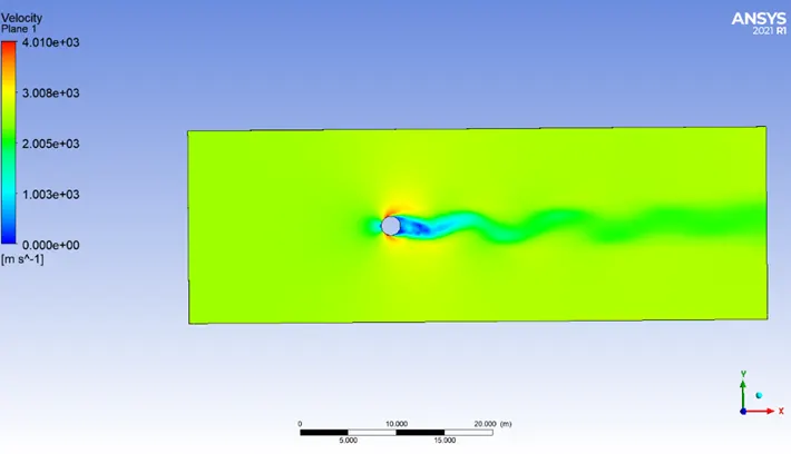
Reynolds number - 1000
Convergence plot
Pressure contour
Velocity contour
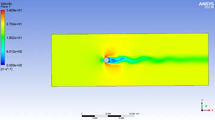
Reynolds number - 10000
Convergence plot
Pressure plot
Velocity contour
Reynolds number - 100000
Convergence plot
Pressure contour
Velocity contour
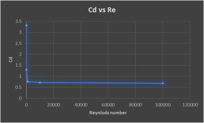
2) Coefficient of lift and drag was calculated at steady state condition for various Reynolds number
Variation of Cd with Re
|
Re |
Cd |
|
10 |
3.322 |
|
100 |
1.296 |
|
1000 |
0.7555 |
|
10000 |
0.7214 |
|
100000 |
0.6768 |
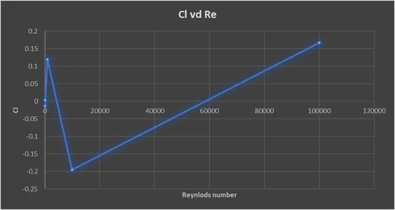
Variation of Cl with Re
|
Re |
Cl |
|
10 |
0.00365 |
|
100 |
-0.01328 |
|
1000 |
0.11913 |
|
10000 |
-0.19496 |
|
100000 |
0.16737 |
Variation of Vertex average velocity
|
Re |
Va (m/s) |
|
10 |
0.1104 |
|
100 |
0.9837 |
|
1000 |
13.7856 |
|
10000 |
135.1238 |
|
100000 |
1629.316 |
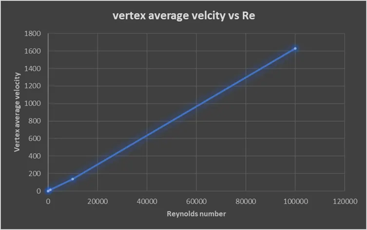
- From above plots we can observe, with increase in Reynolds number there is decrease in Coefficient of drag and there is fluctuation of Cl in positive and negative value , which can be said in harmonic motion also as mentioned above with increase in Reynolds number there is increase in Vortex shedding which is observed here in vertex velocity value.