Week 2 - Flow over a Cylinder.
Aim:-
Simulate the flow over a cylinder and explain the phenomenon of Kaman vortex street. Understanding the vortex shedding for different Reynolds numbers by changing the inlet velocities.
THEORY:
Flow over cylinder: In spite of extensive experimental and numerical studies almost over a century, flow around a circular cylinder still
remains a challenging problem in fluid mechanics, where intensive investigations are continued even today to
understand the complex unsteady dynamics of the cylinder wake flow. Cross-flow normal to the axis of a stationary
circular cylinder and the associated problems of heat and mass transport are encountered in a
wide variety of engineering applications. Both experimental measurements and numerical computations have
confirmed the onset of instability of the wake flow behind a cylinder beyond a critical Reynolds number, leading
finally to a kind of periodic flow identified by definite frequencies, well-known in the literature as the Von Karman
vortex street. In case of laminar flow past cylinders with regular polygonal cross-section, the flow
usually separates at one or more sharp corners of the cross-section geometry itself, forming a system of vortices in
the wake on either side of the mid symmetry plane. On the other hand, for a circular cylinder, where the point of flow
separation is decided by the nature of the upstream boundary layer, the physics of the flow is much more complex
than what its relatively simple shape might suggest.
Reynolds Number: It is defined as the ratio of inertial forces to viscous forces within the fluid which is subjected to
relative internal movement due to different fluid velocities. The region where these forces change behavior is known
Boundary layer. This relative movement generates fluid friction, which is a factor in developing turbulent flow.
Counteracting this effect is the viscosity of the fluid, which tends to inhibit turbulence. The Reynolds number
quantifies the relative importance of these two types of forces for given flow conditions and is a guide to when the
turbulent flow will occur in a particular situation. This ability to predict the onset of turbulent flow is an important
design tool for equipment such as piping systems and aircraft wing.
With respect to laminar and turbulent flow regimes:
laminar flow occurs at low Reynolds numbers, where viscous forces are dominant, and is characterized by
smooth, constant fluid motion;
turbulent flow occurs at high Reynolds numbers and is dominated by inertial forces, which tend to produce
chaotic eddies, vortices, and other flow instabilities.
Mathematically Reynolds Number is defined as:
Re =ρuD/μ
ρ- Density of the fluid.
u= Velocity of the fluid.
D= Diameter of the tube or cylinder.
μ= Dynamic viscosity.
CASE Setup :-
CAD clean up/Pre-process-SpaceClaim - Generate the surface in spaceclaim by using the given data.
Meshing :- Apply boundary names at different faces and generate the mesh by giving the value element size. Apply mesh sizing and inflation.
Setup :- In this section, we set up the simulation. Laminar model is applied for simulatuin. We change the material properties (density and viscosity). And then we apply cell zone condition for simulation. we apply different boundary conditions like inlet , outlet boundary conditions. Then we prepare the report definition for Average vortex velocity magnitude at certain point lies 8m from the center of the cylinder, Lift coefficient, Drag coefficient over the cylinder. After this initialize the process. Prepare Contour plots for pressure and velocity and animation for those . Certain No of iterations are set for simulation.
Solution :- We get the plot of residual, Average vortex velocity magnitude, Lift coefficient, Drag coefficient. And we can see the animations for pressure and velocity contour.
Results :- Post processing is carried in this section in which different contours are obtained to visualize the properties (such as temperature and velocity) for which simulation is run.
Set up of geometry
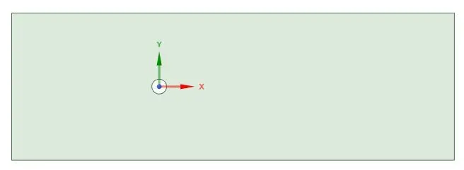
CAD clean up/Pre-process-SpaceClaim - Creating the geometry by sktching using the circle command, circle diameter D=2m. Circle is placed 20m from the inlet. Generate the surface in spaceclaim by using the given data. D=2m, Size of rectangle= 60x20 m. And delete the cylindrical surface.
Meshing:-
Generate the mesh by giving the value element size is equal to 0.25m. By changing the method to the triangle to change the mesh from quadrilateral to to triangle.
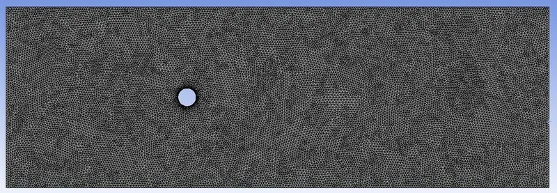
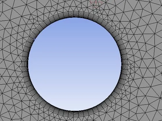
We improve the mesh around the cylinder by sizing in the mesh which is used to conrol precisely the mesh. We should add the inflation which is used to create body filled mesh.
FOR THIS CHALLANGE I AM TAKING THE VALUE OF DENSITY=1 kg/m^3 & DYNAMIC VISCOSITY=0.02 Ns/m^2
PART -1
a) Steady state ,
Re=100 , D = 2, ρ = 1, μ = 0.02 , we get Inlet velocity = 1 m/s
Setup :- In this section, we set steady state Laminar model is applied for simulatuin. We change the material properties (density and viscosity). And then we apply cell zone condition for simulation. we apply different boundary conditions like inlet , outlet boundary conditions. Then we prepare the report definition for Average vortex velocity magnitude at certain point lies 8m from the center of the cylinder, . After this initialize the process. Prepare Contour plots for pressure and velocity and animation for those . Certain No of iterations are set for simulation.
Solution:-
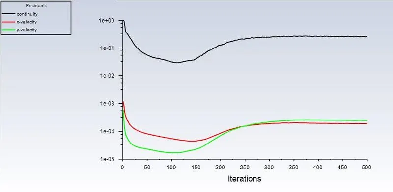
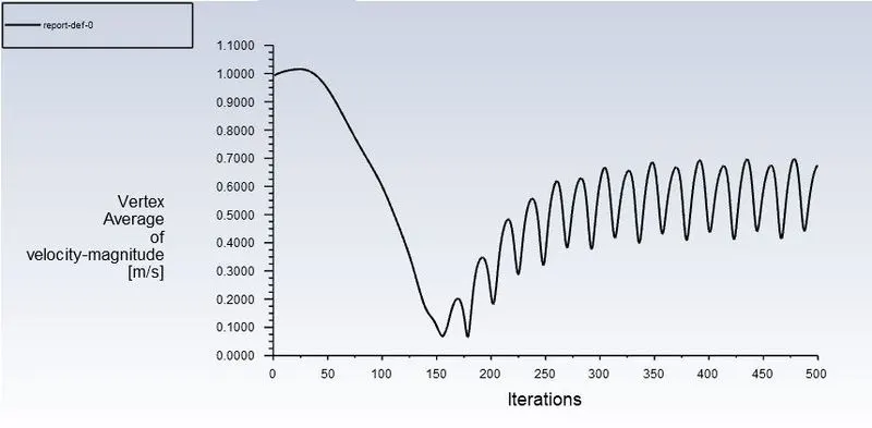
No of iteration= 500
Residuals:-
Vertex average of velocity magnitude:-
Results:-
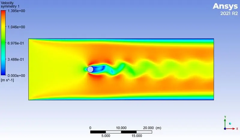
Velocity contour:-
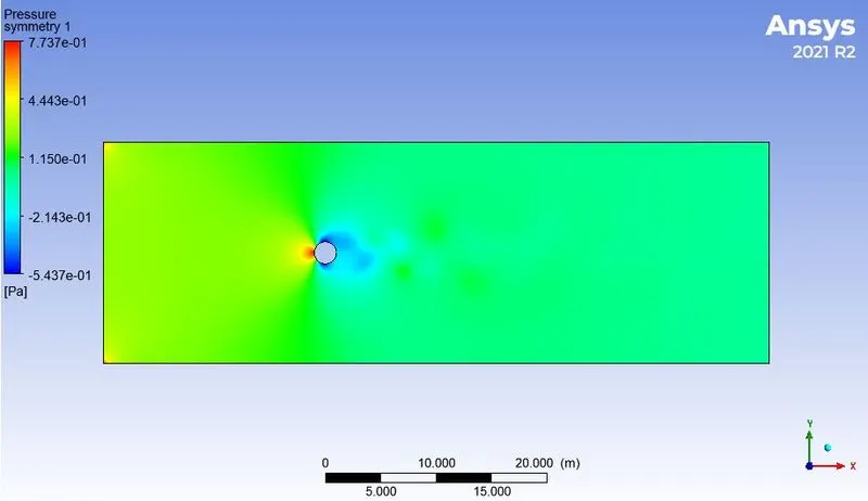
Pressure contour:-
b) Unsteady state
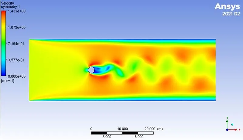
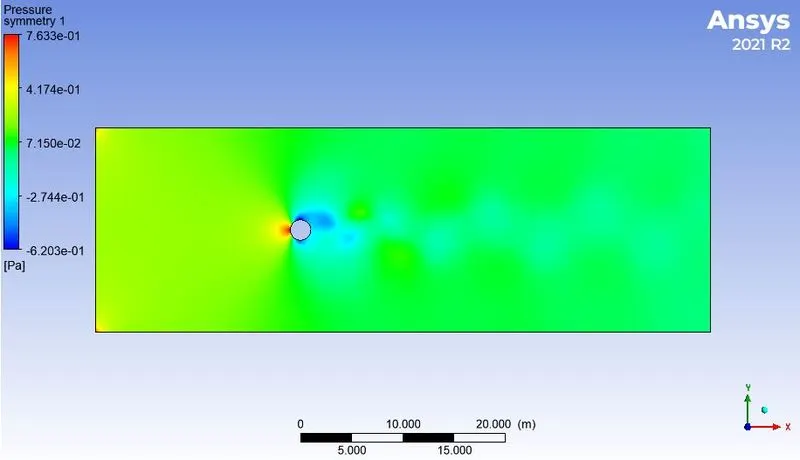
Re=100 , D = 2, ρ = 1, μ = 0.02 , we get Inlet velocity = 1 m/s
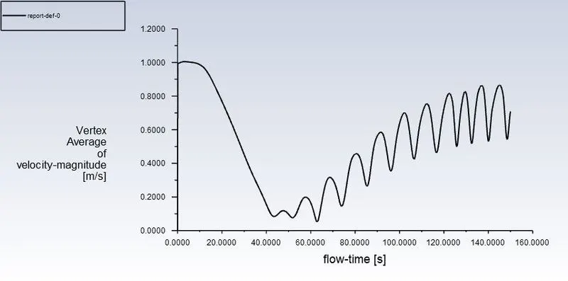
Setup :- In this section, Transient state Laminar model is applied for simulatuin. We change the material properties (density and viscosity). And then we apply cell zone condition for simulation. we apply different boundary conditions like inlet , outlet boundary conditions. Then we prepare the report definition for Average vortex velocity magnitude at certain point lies 8m from the center of the cylinder, . After this initialize the process. Prepare Contour plots for pressure and velocity and animation for those . Certain No of iterations are set for simulation.
Solution:-
Time step size = 0.1s
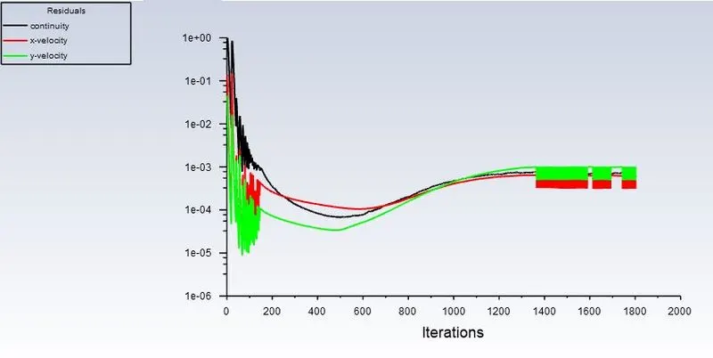
No of time steps = 1500
Residuals:-
Vertex average of velocity magnitude:-
Results:-
Velocity contour:-
Pressure contour:-
PART - 2
Re=10 , D = 2, ρ = 1, μ = 0.02 , we get Inlet velocity = 0.1 m/s
Setup :- In this section, we set steady state Laminar model is applied for simulatuin. We change the material properties (density and viscosity). And then we apply cell zone condition for simulation. we apply different boundary conditions like inlet , outlet boundary conditions. Then we prepare the report definition for Average vortex velocity magnitude at certain point lies 8m from the center of the cylinder, Lift coefficient, Drag coefficient over the cylinder. After this initialize the process. Certain No of iterations are set for simulation.
Solution:-
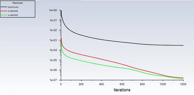
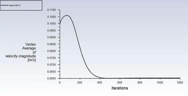
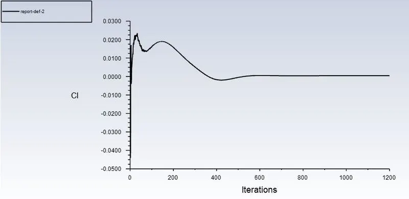
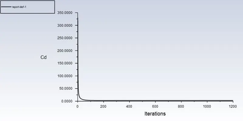
No of iteration= 1200
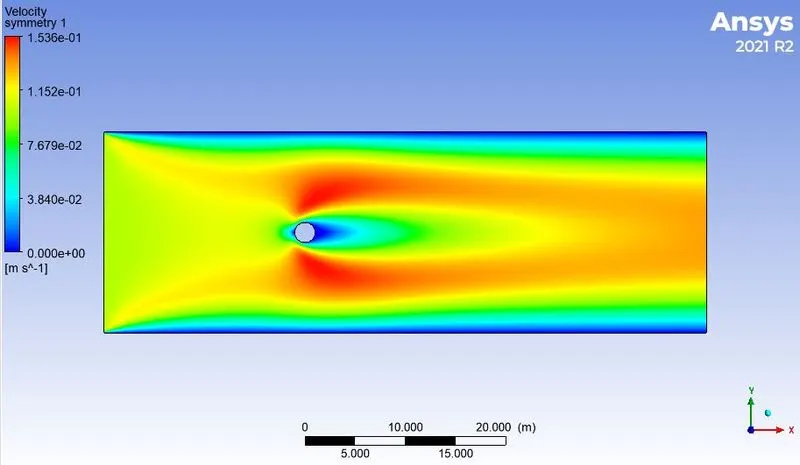
a) Re = 10, D = 2, ρ = 1, μ = 0.02 , we get Inlet velocity = 0.1 m/s
Residuals:-
Vertex average of velocity magnitude:-
Lift coefficient:-
Drag cofficient:-
Results:-
Velocity contour:-
Pressure contour:-
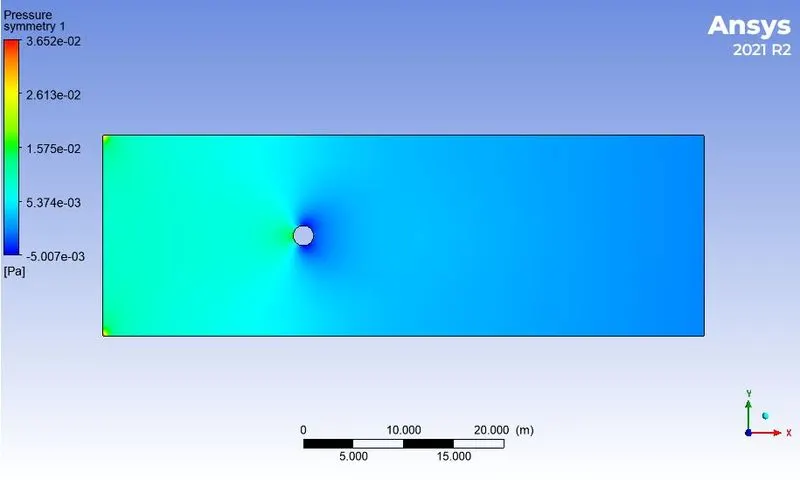
b) Re = 100, D = 2, ρ = 1, μ = 0.02 , we get Inlet velocity = 1 m/s
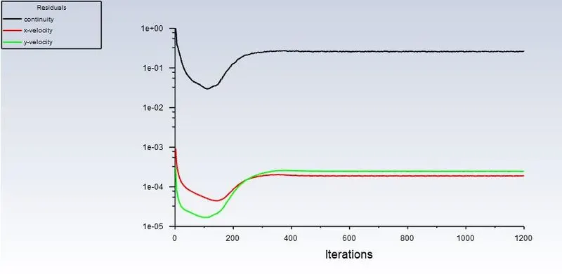
Residuals:-
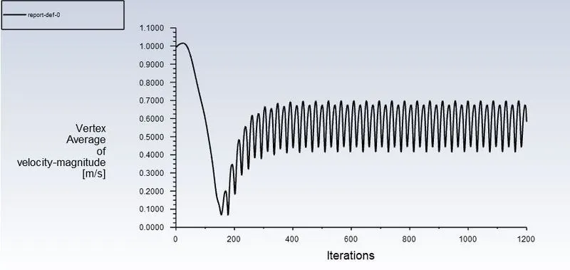
Vertex average of velocity magnitude:-
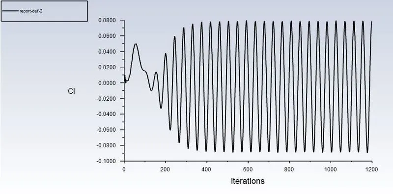
Lift coefficient:-
Drag cofficient:-
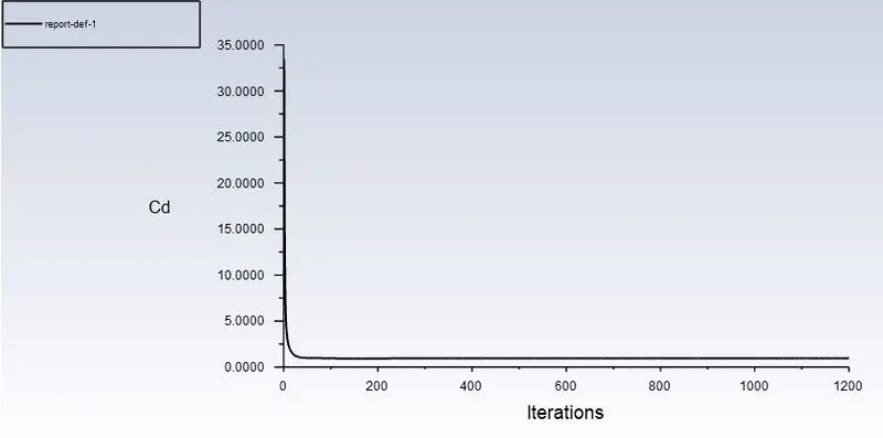
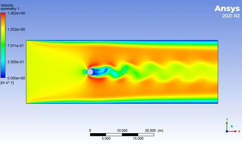
Results:-
Velocity contour:-
Pressurecontour:-
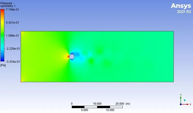
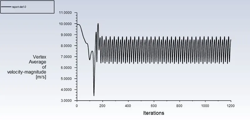
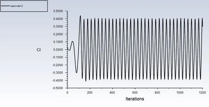
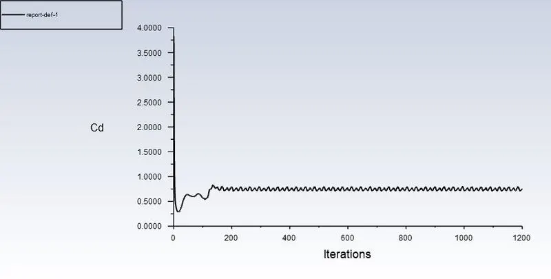
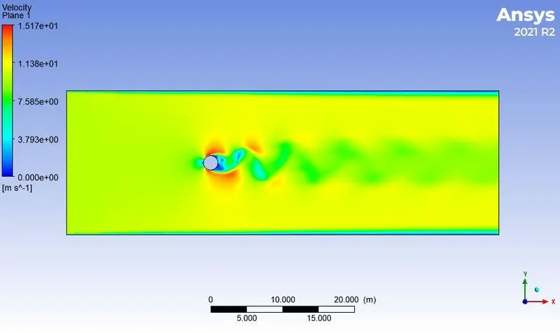
c) Re = 1000, D = 2, ρ = 1, μ = 0.02 , we get Inlet velocity = 10 m/s
Residuals:-
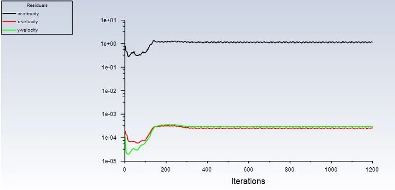
Vertex average of velocity magnitude:-
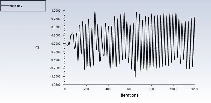
Lift coefficient:-
Drag cofficient:-
Results:-
Velocity contour:-
Pressurecontour:-
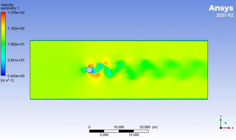
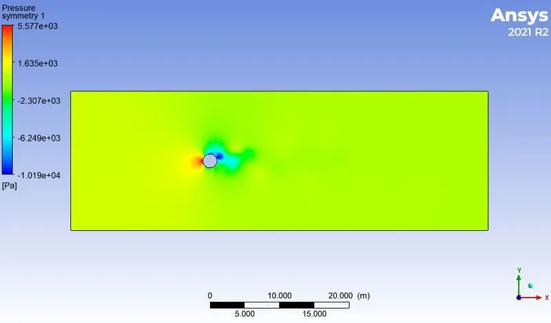
d) Re = 10000, D = 2, ρ = 1, μ = 0.02 , we get Inlet velocity = 100 m/s
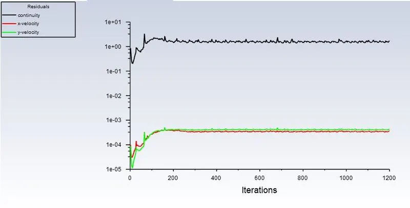
Residuals:-
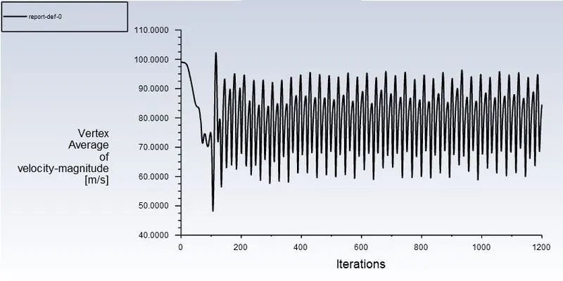
Vertex average of velocity magnitude:-
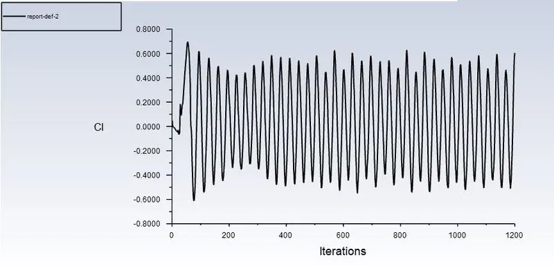
Lift coefficient:-
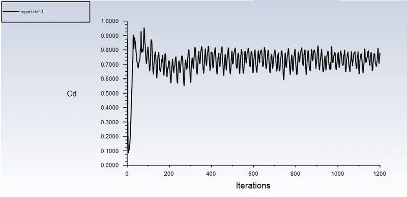
Drag cofficient:-
Results:-
Velocity contour:-
Pressurecontour:-
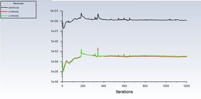
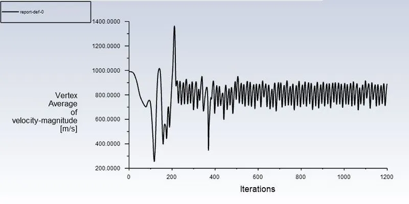
e) Re = 100000, D = 2, ρ = 1, μ = 0.02 , we get Inlet velocity = 1000 m/s
Residuals:-
Vertex average of velocity magnitude:-
Lift coefficient:-
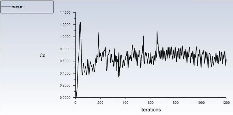
Drag cofficient:-
Results:-
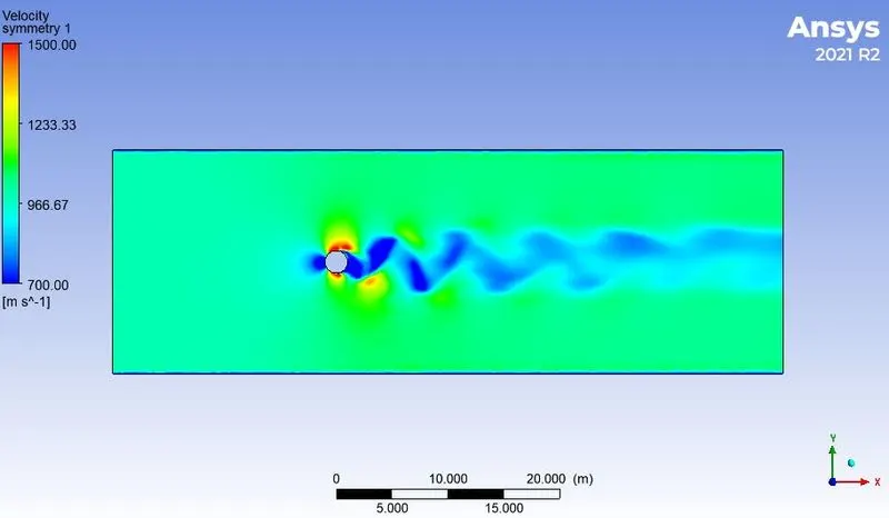
Velocity contour:-
Pressure contour:-
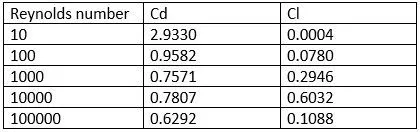
Drag and Lift coefficient for different Re:-
Conclusion:-
If we compare the data in the table, it is seen that as Reynolds number is increasing the coefficient of Drag is
decreasing and coefficient of lift is increasing.
This phenomenon is happening because of when Reynold number get increased the surface friction between fluid
and cylinder is also increasing which casue the boundary layer to break before flow seperated hence amount of
drag get decreases and lift get increases.
As the Reynold number increase in value the wake region behind the cylinder is also increasing which results in
bigger domain capturization for further simulations.
In order to observe the behavior of the drag coefficients for the simulations, the velocity of the flow is varied to
change the Reynolds number and the rest of the parameters are kept constant.
For Re=10, it is observed that there is no formation of vortex shedding and in the rest of the cases, it is clearly
observed.
For lower Reynolds number the vortices are bit symmetrical in nature but as Reynolds number get increase it start
to deviate more.
It can be seen that the steady state solver are more time friendly compared with transient one but Non-iterative
Time Advance method can provide better opportunity to solve same trasient problem with less number iteration and
time also.
In the first case, the flow over a cylinder is simulated for both Steady and unsteady cases with Re=100, and with
the results generated the phenomena of Von Karman Vortex Street are also observed.
Necessary plots are plotted in order to observe that the flow is converged and the vortex shedding is
happening.
Contours are generated in order to observe the flow over a cylinder.