Week 2 - Flow over a Cylinder.
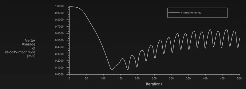
AIM: Simulate the flow over a cylinder and explain the phenomenon of Karman vortex street. Understanding the vortex shedding for different Reynolds numbers by changing the inlet velocities accordingly. Create a monitor point behind the cylinder at a distance 4 times the diameter which can be used to calculate and analyze the vortex shedding:
OBJECTIVE:
PART-I
- Simulate the flow with the steady and unsteady case and calculate the Strouhal Number for Re= 100.
PART-II
- Calculate the coefficient of drag and lift over a cylinder by setting the Reynolds number to 10,100,1000,10000 & 100000. (Run with a steady solver).
- Discuss the effect of Reynolds number on the coefficient of drag. ( Results should be validated with any standard literature and error should be within 5 %).
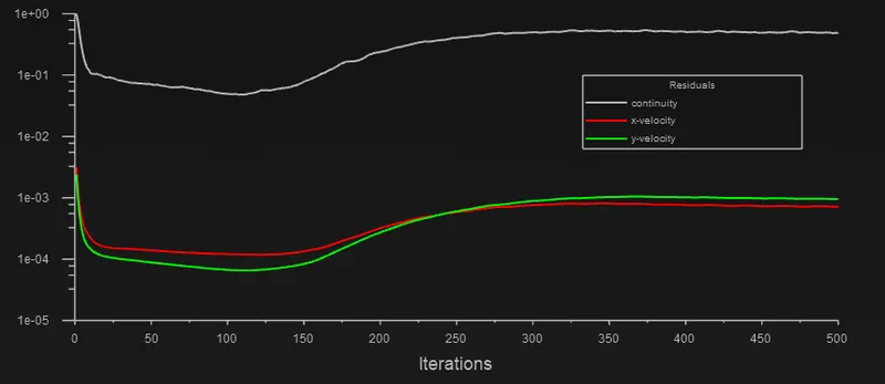
- In both approaches, show that the flow has converged. That is, what quantities or plots need to be looked at to determine that the flow has converged?
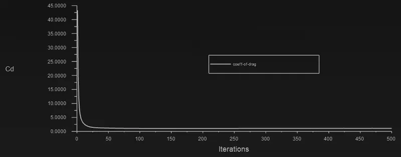
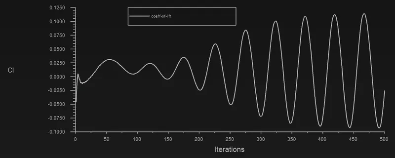
- Plots of the coefficient of drag and lift.
- Plots to show vortex shedding behind the cylinder.
- Mention the preferred material at the end of the challenge submission page.
THEORY AND EXPLANATION:
- Flow over cylinder:
In spite of extensive experimental and numerical studies almost over a century, flow around a circular cylinder still remains a challenging problem in fluid mechanics, where intensive investigations are continued even today to understand the complex unsteady dynamics of the cylinder wake flow. Cross-flow normal to the axis of a stationary circular cylinder and the associated problems of heat and mass transport are encountered in a wide variety of engineering applications. Both experimental measurements and numerical computations have confirmed the onset of instability of the wake flow behind a cylinder beyond a critical Reynolds number, leading finally to a kind of periodic flow identified by definite frequencies, well-known in the literature as the Von Karman vortex street. In case of laminar flow past cylinders with regular polygonal cross-section, the flow usually separates at one or more sharp corners of the cross-section geometry itself, forming a system of vortices in the wake on either side of the mid symmetry plane. On the other hand, for a circular cylinder, where the point of flow separation is decided by the nature of the upstream boundary layer, the physics of the flow is much more complex than what its relatively simple shape might suggest.
- Strouhal number:
In dimensional analysis, the Strouhal number is a dimensionless number describing oscillating flow mechanisms.
For large Strouhal numbers (order of 1), viscosity dominates fluid flow, resulting in a collective oscillating movement of the fluid "plug". For low Strouhal numbers (order of 10 and below), the high-speed, quasi-steady-state portion of the movement dominates the oscillation. Oscillation at intermediate Strouhal numbers is characterized by the buildup and rapidly subsequent shedding of vortices.
The Strouhal number is often given as,
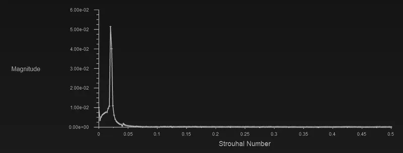
St = f*d/u
Where,
f= frequency of vortex shedding.
d= characteristic diameter of the cylinder.
u= fluid flow velocity.
3.Reynolds number:-
The Reynolds number is defined as ratio of inertial forces to viscous forces within a fluid which is subjected to relative internal movement due to different fluid velocities.
Where:
Re= (ρLu)/ (µ);
= (Lu)/ (ν)
ρ is the density of the fluid (SI units: kg/m3).
u is the flow speed (m/s).
L is a characteristic linear dimension (m) (see the below sections of this article for examples).
μ is the dynamic viscosity of the fluid (Pa·s or N·s/m2 or kg/(m·s)).
ν is the kinematic viscosity of the fluid (m2/s).
Flow characteristics flow over a cylinder for different Reynolds number:
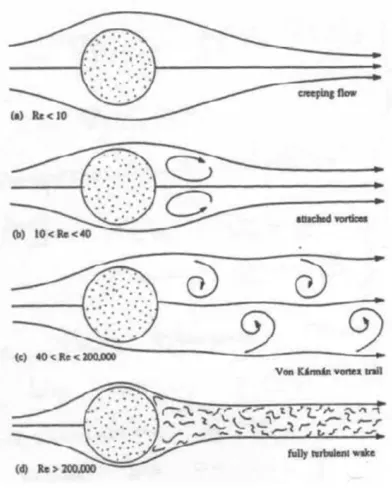
Steady state and transient state for re-100
Case (c) Re-100
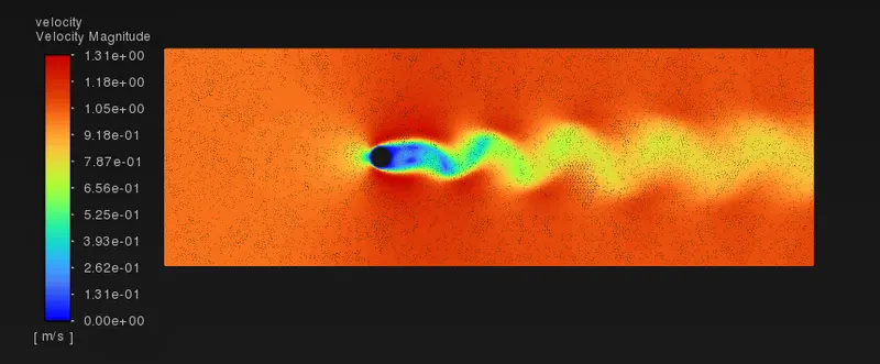
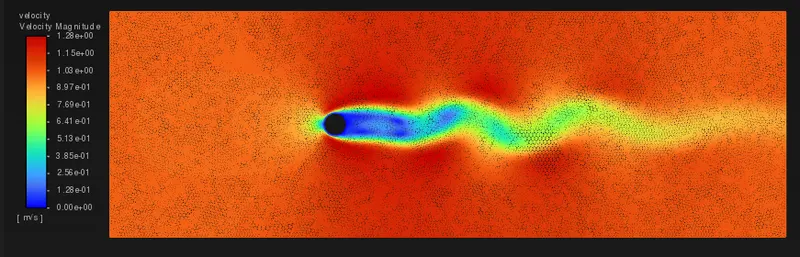
The flow over a cylinder in case(c) causes boundary separations and causes oscillating wakes at lower pressure side (right side in the fig c) these wiggles are named as Kármán Vortex Street.
4.Coefficient of drag:
Drag Coefficient is a dimensionless quantity that is used to quantify the resistance of an object. It is used in the drag equation in which a lower drag coefficient indicates less aerodynamic or hydrodynamic drag.
The formula for Coefficient of drag (cd):
Cd=2.Fd/ρ.V^2.A
where Fd is the drag force in N.
ρ - density of the material in kg/m3kgm3.
V - velocity of the inlet flow in m/s.
A - area of the object in m2m2, here A is an area of a cylinder with a diameter of 2m.
5.Lift Coefficient:-
The lift coefficient is a non-dimensionless quantity that relates to the lifting force to the density of the fluid and velocity of the fluid and associated area of the object.
The formula for Coefficient of lift(Cl):-
Cl=2.Fl/ρ.V^2.A
Where Fl is the lift force in N.
ρ- density of the material in Kg/m^3.
V - velocity of the inlet flow in m/s.
A - area of the object in m2, here A is an area of a cylinder with a diameter of 2m.
6.Vortex Shedding:
Vortex shedding is an oscillating flow that takes place when a fluid flows past a blunt body at a certain velocity. In this flow, the boundary layer separated from the surface forms a sheer layer that rolls into the vortex and detaches from the surface whereas in Von Karman Vortex Street shedding occurs from both the sides of the body which interact with each other. They shed alternatively from the cylinder and generate a regular vortex pattern called Karman Vortex Street.
A Karman vortex street (or a von Kármán vortex street) is a repeating pattern of swirling vortices, which is caused by a process known as vortex shedding. It is responsible for the unsteady separation of flow of a fluid flow around the blunt bodies.
In fluid dynamics, vortex shedding is an oscillating flow that takes place when a fluid such as air or water flows past a bluff (as opposed to streamlined) body at certain velocities, depending on the size and shape of the body. In this flow, vortices are created at the back of the body and detach periodically from either side of the body forming a Von Kármán vortex street. The fluid flow past the object creates alternating low-pressure vortices on the downstream side of the object. The object will tend to move toward the low-pressure zone.
Von Karman vortices form almost everywhere where the fluid flow is disturbed by an obstruction. And such a regular pattern of vortices called a " Von Karman vortices”. The phenomenon arises under certain flow conditions, expressed commonly by the dimensionless Reynolds number.
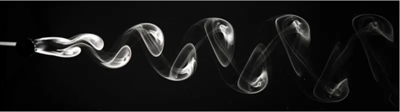
If the bluff structure is not mounted rigidly and the frequency of vortex shedding matches the resonance frequency of the structure, then the structure can begin to resonate, vibrating with harmonic oscillations driven by the energy of the flow. This vibration is the cause for overhead power line wires humming in the wind and for the fluttering of automobile whip radio antennas at some speeds. Tall chimneys constructed of thin-walled steel tubes can be sufficiently flexible that, in air flow with a speed in the critical range, vortex shedding can drive the chimney into violent oscillations that can damage or destroy the chimney.
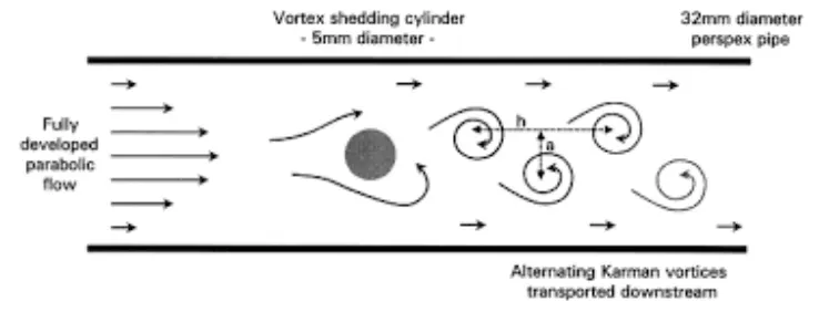
vortex street created by an aerodynamic object for reference.
FORMULA:-
ReL= V L / ν
ReL= ρV L / μ
Where,
V= the free stream flow velocity (m/s).
L= characteristic length parameter of the body or channel (m).
ρ = the reference fluid density(kg / m^3).
μ = kinematic viscosity (=dynamic viscosity/density = μ/ρ) (m^2 / s).
PROCEDURE:-
Dimensions of the Geometry:
Total length = 60m.
Total Width = 20m.
Diameter of the cylinder = 2m.
Distance between inlet and center of the cylinder = 10D = 20m.
Distance between outlet and center of the cylinder = 20D = 40m.
Setup:
Creating this geometry in space claim:-
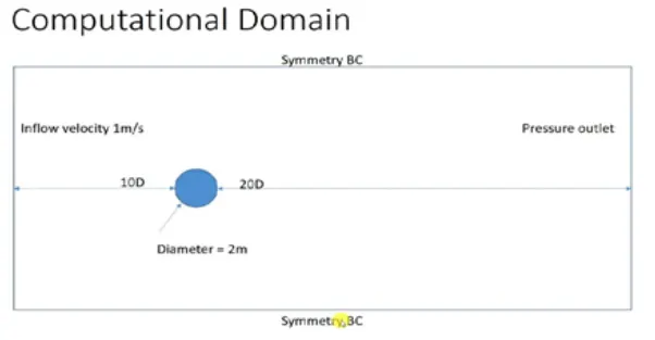
- For modelling the approach we are starting with the creation of geometry.
- First we get into the geometry section where we create the geometry using the space claim.
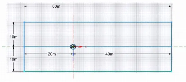
- First we select the unit in meters as required dimensions are given we create the geometry using the tools.
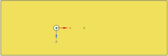
- We remove the extra edges using the deleting construction lines. We use pull command to make it a surface and we remove the circular area to create the cylinder.
- We use a meshing tool to mesh the geometry. 6. We create the mesh by giving the element size i.e 0.25 meters.
- If we are not getting the correct results for this element size , again we change the mesh size to capture the solution correctly.
- After meshing we create the named selections of boundaries. we gave the name to each of the faces of the boundaries.
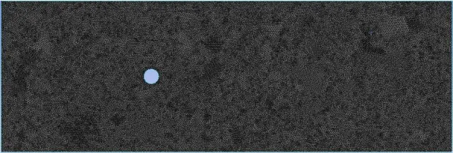
8.But in the meshing nodes, the shape is more quadrilateral than the triangle so we should do this by changing the method to the triangle in the insert option.
- After changing the node's shape into triangles we should improve the mesh around the cylinder by sizing in the mesh which is used to precisely control the mesh.
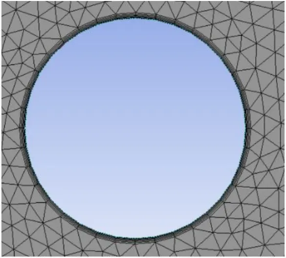
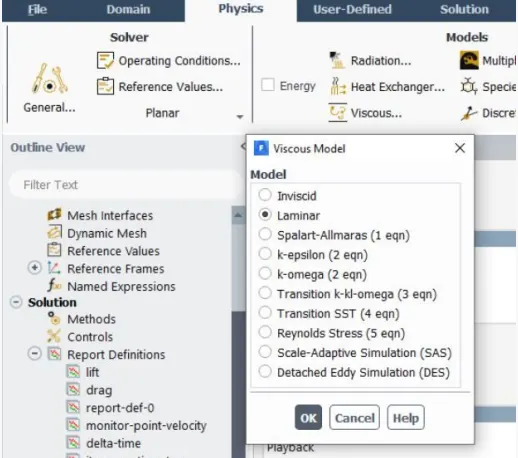
10.Before opening the set up we should update the mesh. Then we should change the viscous flow to laminar.
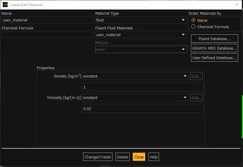
11.Open Materials and create a fluid that is to be used for the simulation for this case, it is air and also inputs the density and kinematic viscosity values.
PART-I
STEADY STATE SIMULATION:
Simulate the flow with the steady case and calculate the Strouhal number for Re=100 and velocity 1m/s:
VELOCITY CONTOUR:
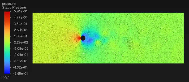
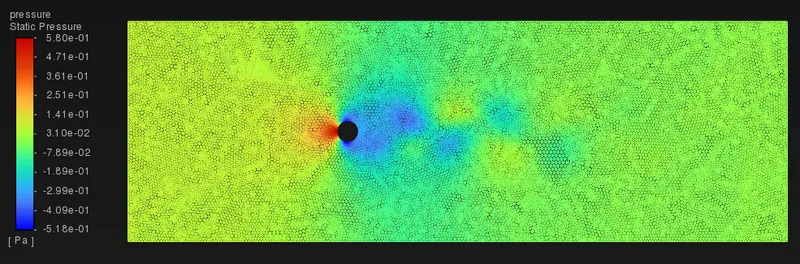
PRESSURE CONTOUR:
RESIDUAL PLOT:
VERTEX AVERAGE VELOCITY PLOT:
COEFFICIENT OF DRAG PLOT:
COEFFICIENT OF LIFT PLOT:
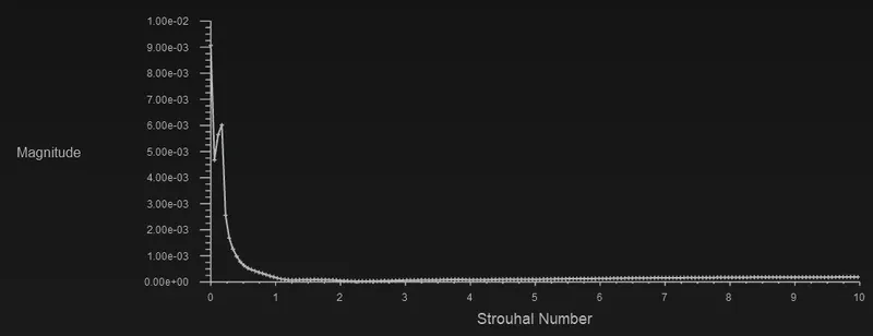
STROUHAL NUMBER:
TRANSIENT STATE SIMULATION:
Simulate the flow with the unsteady case and calculate the Strouhal number for Re=100 and velocity 1m/s:
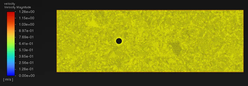
VELOCITY CONTOUR:
PRESSURE CONTOUR:
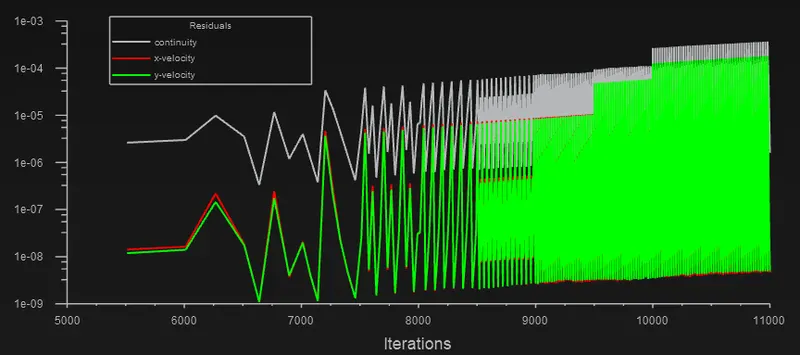
RESIDUAL PLOT:
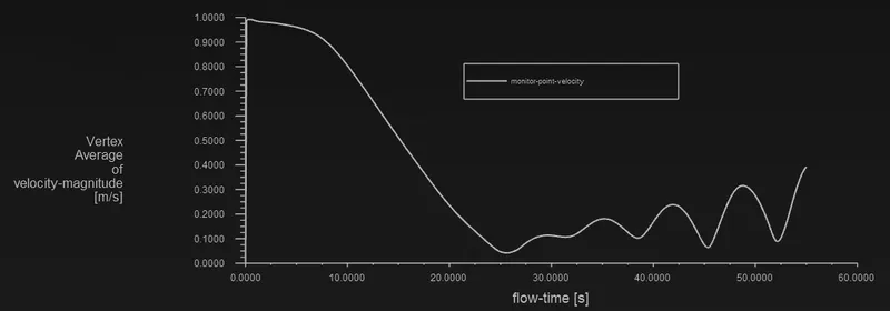
VERTEX AVERAGE VELOCITY PLOT:
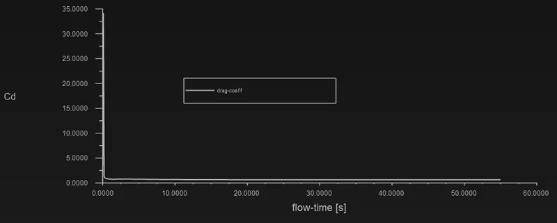
COEFFICIENT OF DRAG PLOT:
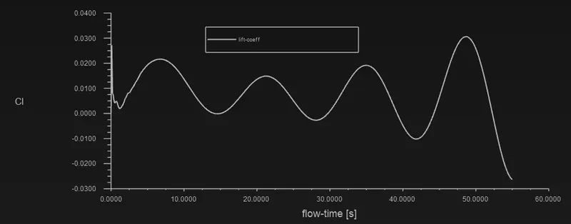
COEFFICIENT OF LIFT PLOT:
STROUHAL NUMBER:
PART-II
STEADY STATE SIMULATION:
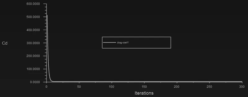
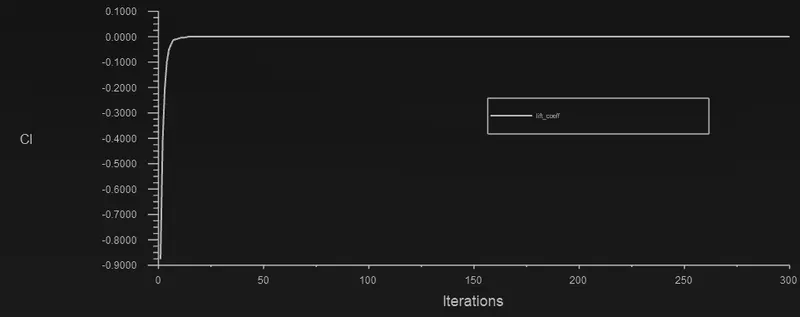
Simulate the flow with the steady case and calculate the Strouhal number for Re=10 and velocity 0.1m/s:
COEFFICIENT OF DRAG PLOT:
COEFFICIENT OF LIFT PLOT:
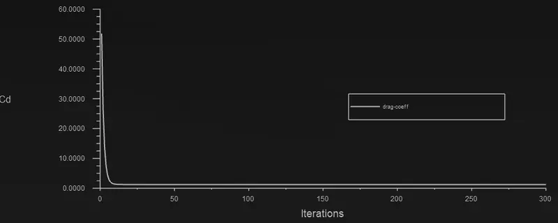
Simulate the flow with the steady case and calculate the Strouhal number for Re=100 and velocity 1m/s:
COEFFICIENT OF DRAG PLOT:
COEFFICIENT OF LIFT PLOT:
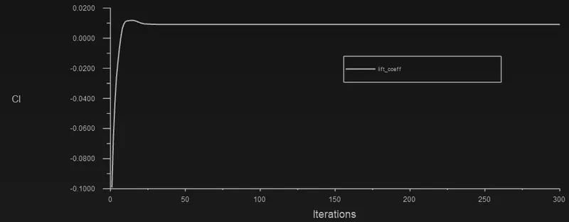
Simulate the flow with the steady case and calculate the Strouhal number for Re=1000 and velocity 10 m/s:
COEFFICIENT OF DRAG PLOT:
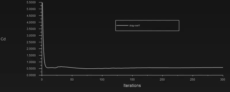
COEFFICIENT OF LIFT PLOT:
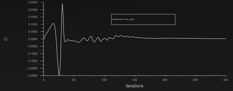
Simulate the flow with the steady case and calculate the Strouhal number for Re=10000 and velocity 100 m/s:
COEFFICIENT OF DRAG PLOT:
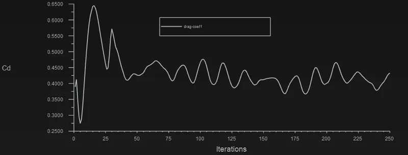
COEFFICIENT OF LIFT PLOT:
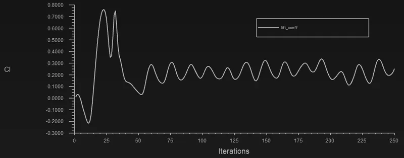
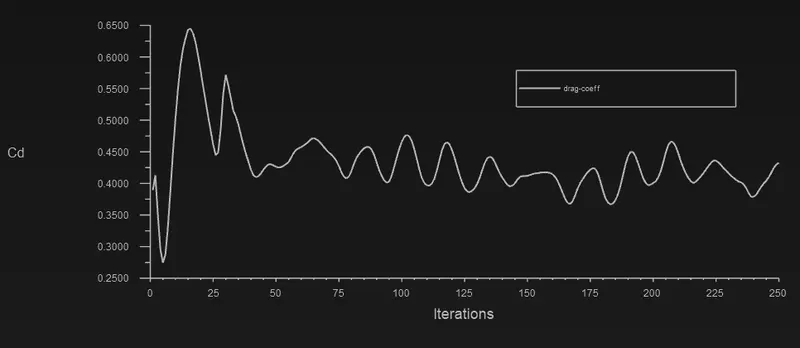
Simulate the flow with the steady case and calculate the Strouhal number for Re=100000 and velocity 1000 m/s:
COEFFICIENT OF DRAG PLOT:
COEFFICIENT OF LIFT PLOT:
Table depicting the effect of Reynolds number on drag coefficient and lift coefficient:-
| Inlet Velocity | Reynolds Number | Coefficient of Drag | Coefficient of Lift |
| 0.1 | 10 | 3.3281628 | 0.00062803886 |
| 1 | 100 | 1.2465985 | 0.0091289538 |
| 10 | 1000 | 0.58205525 | 0.0014446204 |
| 100 | 10000 | 0.41902214 | 0.30857105 |
| 1000 | 100000 | 0.43255673 | 0.25240445 |
CONCLUSION:
1. When the Reynolds number becomes greater than 1000 the oscillations were found to be increasing.
2. As the Reynolds number increases, inertial forces dominate over viscous forces.
3. The coefficient of drag (Cd) is found to be decreasing and the oscillatory nature of the coefficient of lift is observed.
4. The mean value of Vertex average of Velocity and coefficient of lift is found to be increasing with Reynolds number.
5. From the table, with increase in the Reynolds number Drag coefficient is decreasing coefficient of lift increasing.
6. Finally, we observed that along with an increase in the Reynolds number, the flow becomes more and more unsymmetrical.
7. Increasing velocity eventually brings the turbulent drag up to and even higher than the laminar drag value.
8.As Re increases, the vortices are shed alternately from the upper and lower surface of the cylinder at a definite frequency which is a function of Reynolds number.