Week 2 Challenge : Surface meshing on a Pressure valve
SURFACE MESHING ON A PRESSURE VALVE
AIM: Perform the Surface meshing on Pressure valve
OBJECTIVES:
- Target length = 1mm, 3 mm and 5 mm (i.e. 3 cases)
- Element type = Tria
Apply any one target length from the above at a time for the entire model as One case. Submit 3 different models for 3 cases.
INTRODUCTION:
A pressure valve is a device that controls or limits the pressure in a system. It can act as the main pressure relief device or the last line of defense in case of an over-pressure event that could cause damage or danger. A pressure valve can be a pressure control valve, which maintains constant pressure in the system, or a pressure safety valve, which releases excess pressure from the system.
PID is a property ID, which is used to store the specific information about geometrical entities , apply boundary conditions for CFD application. Whole geometry is divided into number of PID’s.
Import Geometry --- Cleanup the Geometry Using TOPO deck --- Apply PID selection --- Meshing the geometry using Classic mesh --- Check quality criteria --- end.
PROCEDURE/STEPS TO MESH THE PRESSURE VALVE:
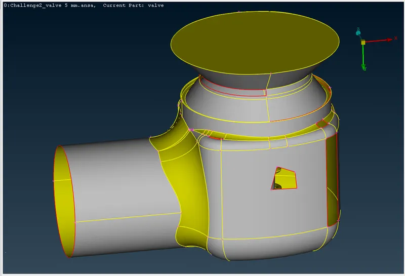
We have to Import the Geometry from web/challenge section.
Imported Geometry:
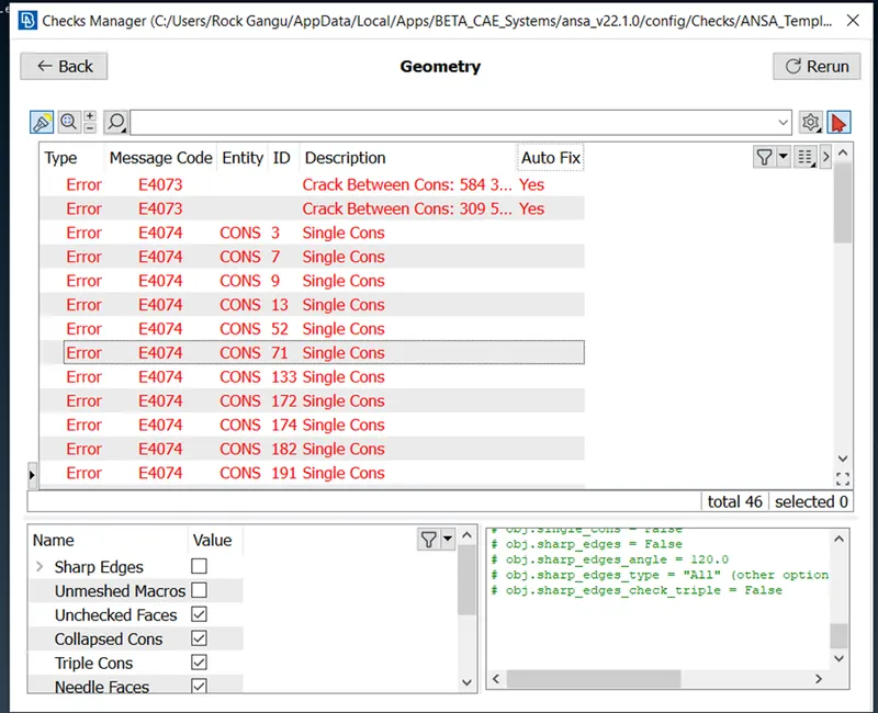
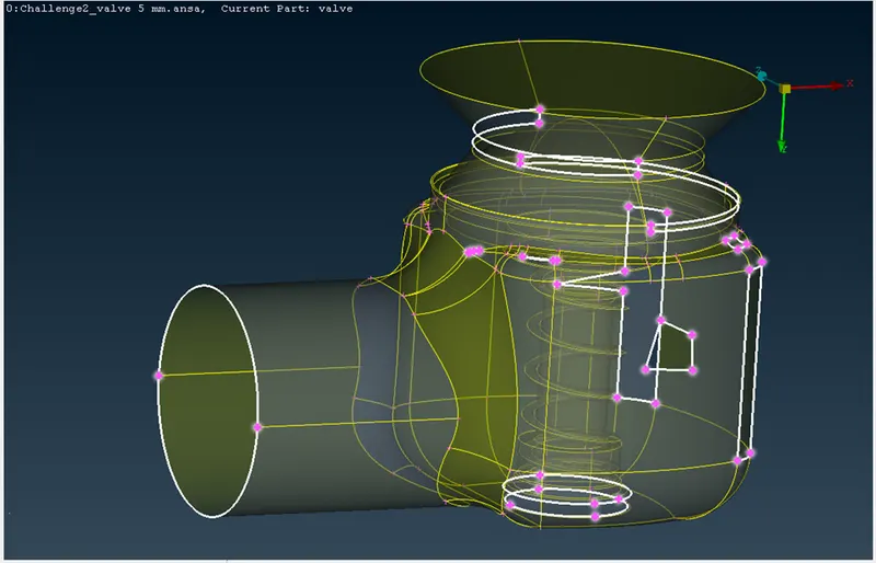
Apply check mesh on Geometry, enable the unmarked conditions then execute the process at that we get errors (single cons) list, by click on them we get those highlighted with wire frame mode.
Errors occurred in Geometry list:
Highlighted Single cons:
Now we have to fill the holes and patches by using TOPO deck.
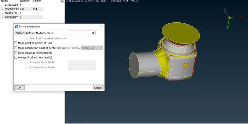
By enabling “Fill Hole”, We can fill the hole with any shaped patch with plane surface. The below Image shows the selection and fill of patch.
Fill the hole of pressure valve using Fill hole topo:
For some patches we need to enable “New” Faces to fill the patch. In that manner we used the Fitted surface type face to fill the patch. Here we used the New faces type coz the fill hole type not capable to fill the patch and it creates the extra edge on the end/creates triple con. In order to that reason we used the new face TOPO deck.
New parameter with Fitted condition:
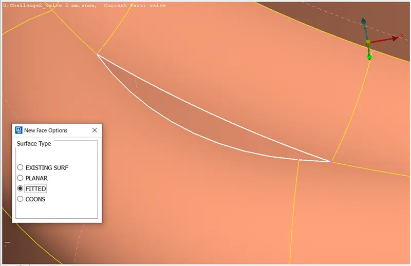
To fill the neck side patch of pressure valve we used the New Face TOPO with Fitted surface. And to avoid the wrong selection of cons we turned on the wire frame and loop option to select the patch with same length of two cons.
Selecting the cons with fitted condition with loop option:
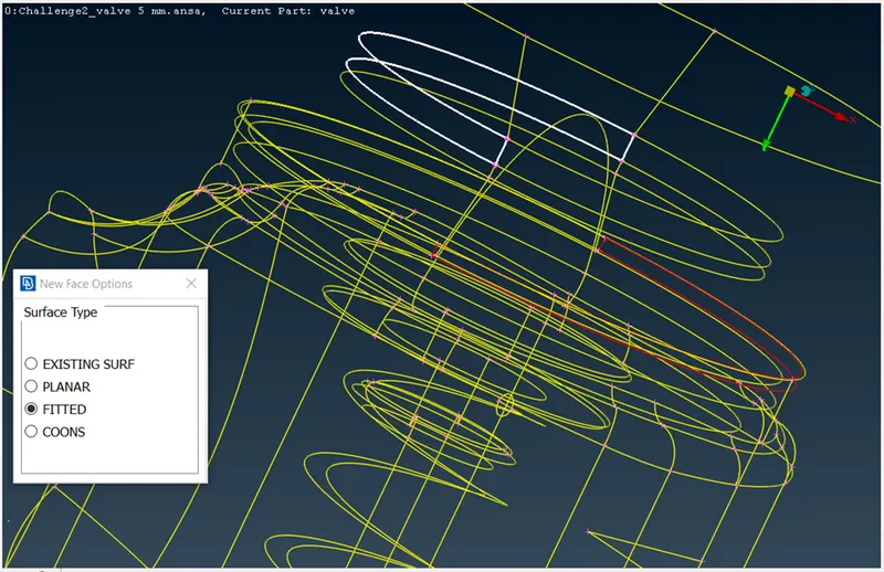
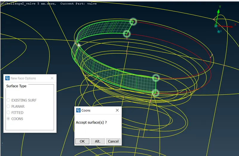
For bottom portion of pressure valve with single cons we used the CINS surface type face to fill the patch. By using the fitted type we get extreme large surface. In that manner we used the CONS type to fit the surface.
Applying CONS condition with ENT option:
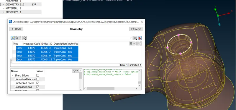
After completing the single con elimination, we have cross check the error occurred on body, so we get back check geometry then we can see that some errors occurred in the mean of triple cons. Those triple cons are negligible and those are not errors in this particular case.
Error with triple cons negligible:
The below image shows the Error/Topo cleaned pressure valve.
Cleaned Geometry:
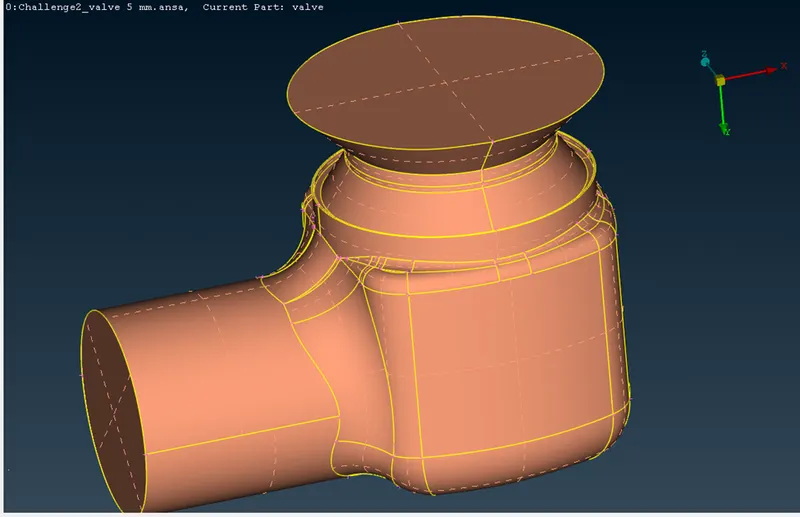
Before going to next section, we have eliminated the small cons which less than the giving mesh size. To avoid the mesh crack or to avoid problem of mesh distribution on body by deploying the mesh. And we removed the extra cons which are appears on a smooth surface are also eliminated to perform the mesh on body without show of critical view of mesh.
In simple words we can say that if any small surfaces or cons or region between two nodes having length less than desired mesh length need to be removed having no significance which may result in mesh failure at that location by using cut.
Some lesser dimension lines or ignored:
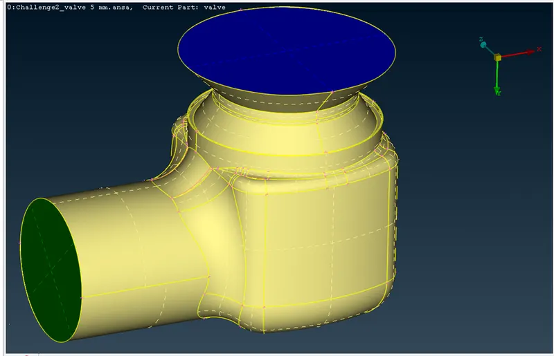
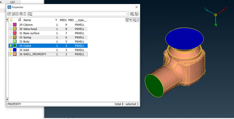
After TOPO deck cleanup we have to set the PID to the pressure valve. Here we create the inlet, outlet, body for outer portion of pressure valve.
Allowing the pressure valve to PID section and creating the Spring, Valve head, Column and Base surface for inner portion of pressure valve. The below image shows the PID applied parts with color difference to identify in smooth manner.
PID applied parts for inlet and outlet:
PID applied body of outer parts:
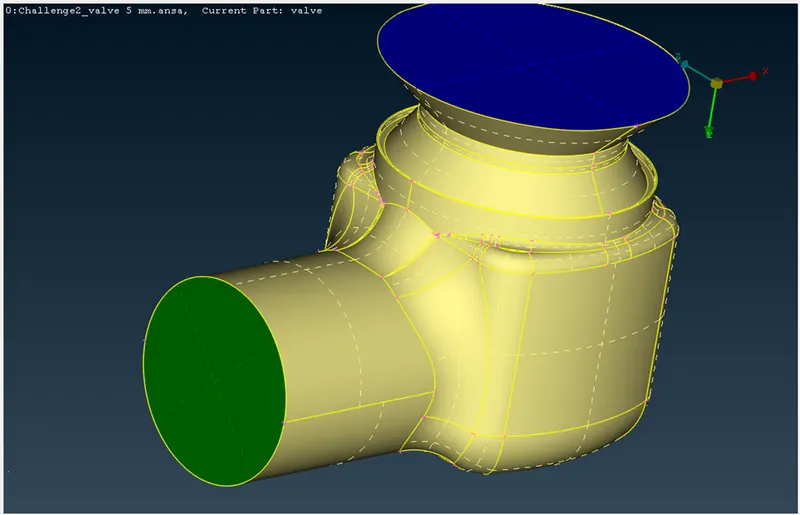
To select/apply the PID to inner parts we used the PID region.
To select the Valve head instead of PID region we used the ENT option to apply the PID on valve head. PID region will select the entire portion of internal part so to avoid the select of attached cons surface we used the ENT option for PID application.
After valve head we select the column by PID region selection method. We applied the different colors to the parts as to identify the part by color.
PID applied on inner parts:
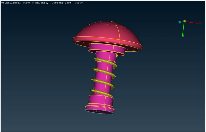
Next, we move to classic mesh section to mesh the pressure valve. In this case we have to set the target length for mesh and type of mesh. For mesh length enable the length parameter in case of perimeter and macros set the same length for both type of parameter.
The below image shows the selection of perimeter length of mesh size of 5mm.For perimeter and macros we set the mesh length as 5mm. And for target mesh length/size set the 5mm and type of Tria shape. For quality criteria enable and allow the minimum and maximum length of mesh as 3 and 7mm.
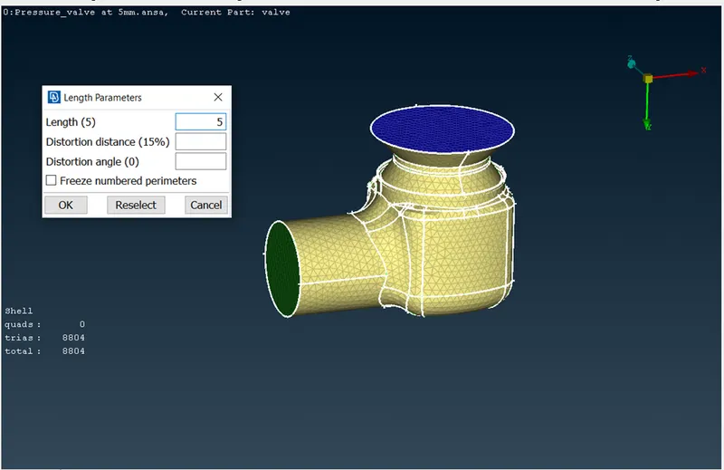
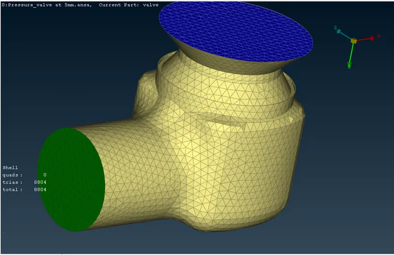
The complete meshed body with 5mm of mesh size/length:
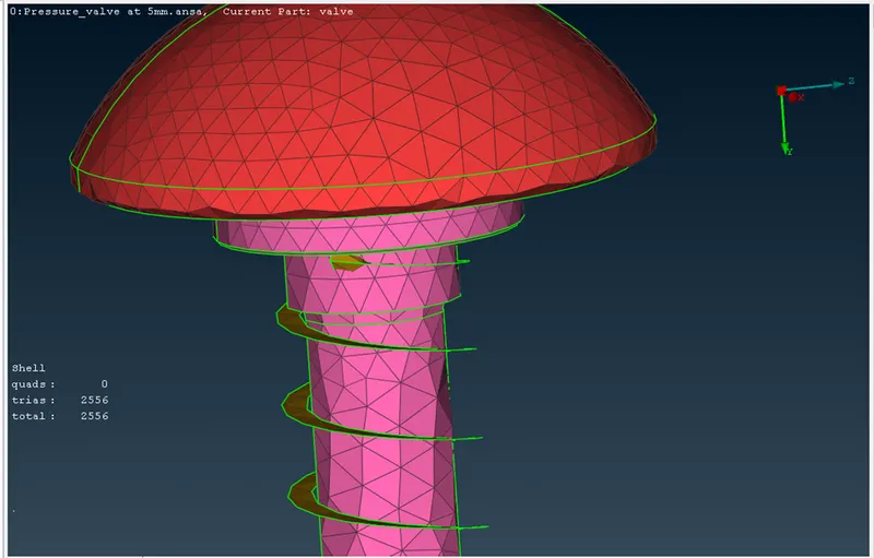
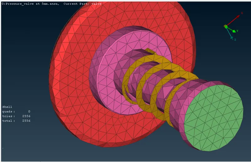
Inner body parts meshed by 5mm mesh size:
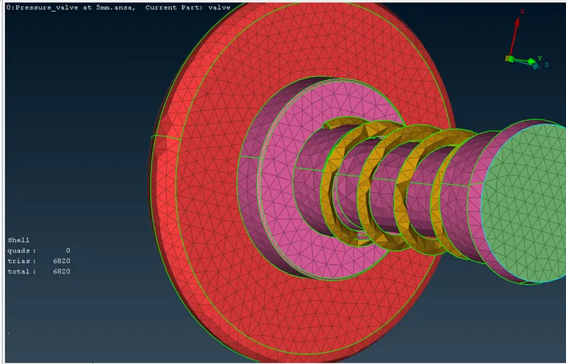
The below image shows the selection of perimeter length of mesh size of 5mm.For perimeter and macros we set the mesh length as 3mm. And for target mesh length/size set the 3mm and type of Tria shape. For quality criteria enable and allow the minimum and maximum length of mesh as 2 and 5mm.
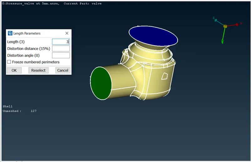
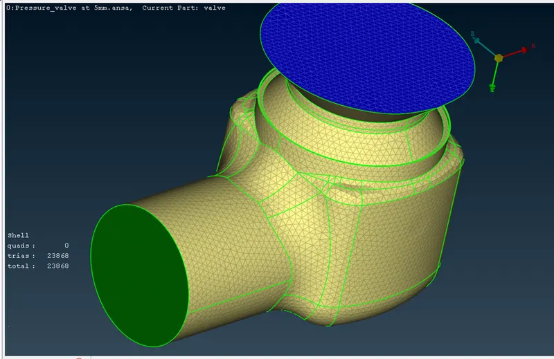
Complete body meshed by 3mm of mesh size/length:
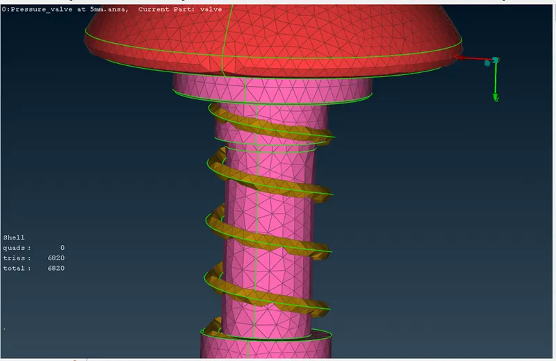
Inner body parts meshed by 3mm mesh size:
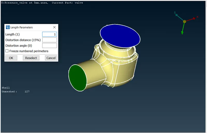
The below image shows the selection of perimeter length of mesh size of 5mm.For perimeter and macros we set the mesh length as 1mm. And for target mesh length/size set the 1mm and type of Tria shape. For quality criteria enable and allow the minimum and maximum length of mesh as 0.5 and 2mm.
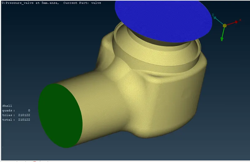
Full body meshed by 1mm of mesh size/length:
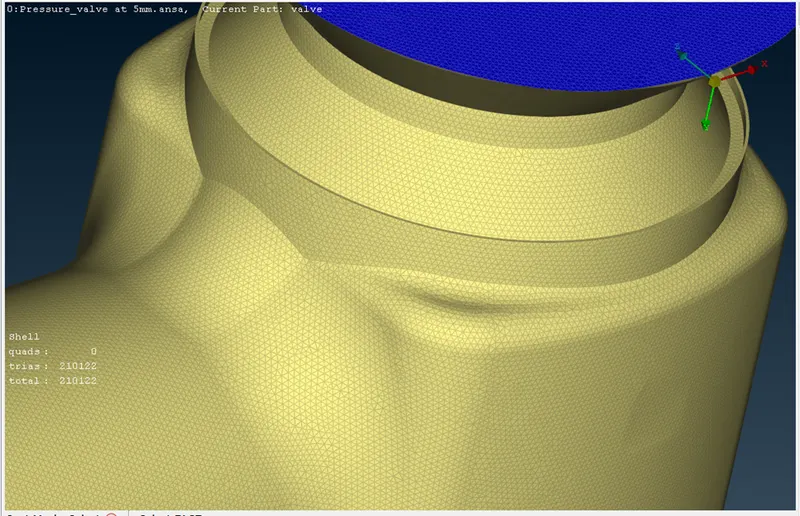
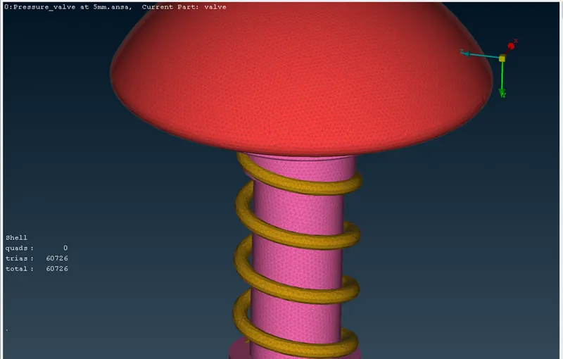
Inner body parts meshed by 1mm size mesh:

LEARNING OUTCOMES:
Correct manner of using the TOPO deck. Topo cleanup. Applying method of PID to the separate parts of the model. Meshing the body with different size of mesh.
RESULTS AND OBSERVATIONS:
|
SI No |
Size/length of mesh |
Total Elements |
Inner parts elements |
|
1 |
5mm |
8804 |
2556 |
|
2 |
3mm |
23868 |
6820 |
|
3 |
1mm |
210122 |
60726 |
From above results we see that as the mesh size decreases the elements are increased.
From the result of images, the outer portion of the pressure valve not so effect with the mesh size of any, but for inner portion of pressure valve parts have the problem of apply of mesh.
For max. of length/size of mesh the spring should seen as flat part and the finishing of the valve head is not so smooth than min. size mesh.
At 5mm mesh size the elements are less and the formation of mesh is rude/hard on the parts of pressure valve. At 3mm mesh size the elements are increased comparing to 5mm mesh size, but here also we can see that the formation of mesh less smooth and edge of valve head is almost seen as smooth curved frame. For 1mm mesh size we can see that the elements are more compare to 3&5mm. Here the formation of mesh smooth and the parts can be seen in their original shapes.
As compare to all 3 type mesh the smaller mesh is best fit the geometry, and it is not disturbs the shape, size of part.
CONCLUSION:
By considering the above results and observation we conclude that as smaller the mesh size we get the best result comparing to max. of mesh size. For this particular pressure valve model we can apply the 1mm mesh for getting the good result.