Week 2 Challenge : Surface meshing on a Pressure valve
AIM:
For the given model, check for the geometrical errors and perform Topology cleanup accordingly. Set three different target lengths as three different cases and mesh the model.
- Target length = 1mm, 3 mm and 5 mm (i.e. 3 cases)
- Element type = Tria
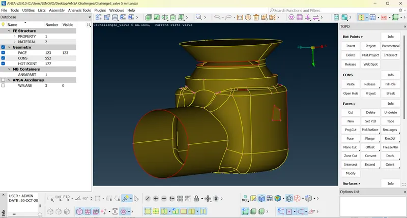
OBJECTIVE:
- Apply any one target length from the above at a time for the entire model as One case. Submit 3 different models for 3 cases
- Submit 3 different files for 3 different mesh length and Conclude by observing all the three cases. Submit all 3 models in Zip along with the report in the Report page of the Portal.
- Additionally optimum meshing with mix of above mentioned target length witrh least number of mesh elements need to be designed.
PROCEDURE:
TOPOLOGICAL CLEANUP
- Under checks- geometrical checks- template-ANSA[AUTO GENERATED TEMPLATE]-visible
- First process is to check for single cons and fill these surfaces so that in latter stages it can be produced for volumetric meshing and CFD analysis.
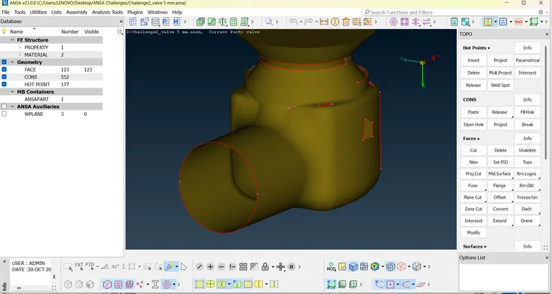
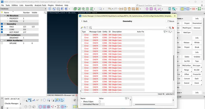
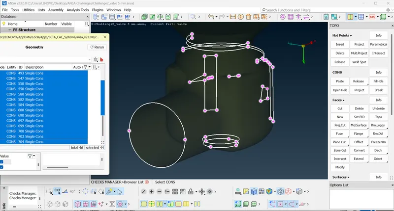
- The process used to remove errors- to remove error if we use TOPO clean up.
- Now for TOPO Cleanup select TOPO deck. In TOPO deck you have a hot points, CONS, faces,, surfaces, curve, points, auxillary.
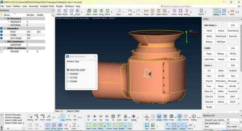
- Face-New-Existing Surf,Planar,Fitted,Coons.(These are different algorithms to obtain new surface).
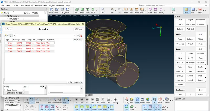
- Now for selection of CON single for coons filling the length of the single CON should we say otherwise it may lead to an equal meshes.
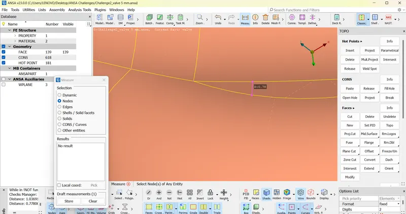
- Small surfaces should not be there in the model as these may interfere in meshing select faces in TOPO clean up. select cut and right click on single CON that makes surfaces smaller.
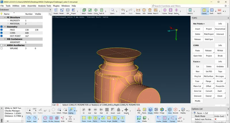
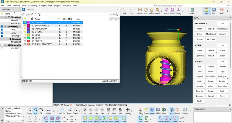
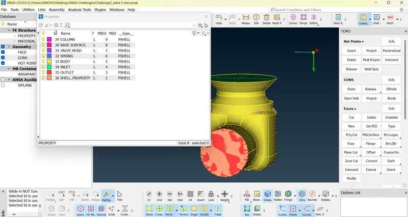
- New PID-New-Pshell-Pshell-Outlet and select outlet area in the model.
- New PID-New-Pshell-Pshell-Inlet and select inlet area in the model.
- New PID-New-Pshell-Pshell-Body and select Body area in the model.
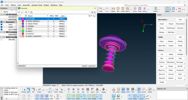
- Isolate by NOT OPTION in visibility tab and select inner spring and New PID-New-Pshell-Pshell-Spring and select spring area in the model.
- New PID-New-Pshell-Pshell-valvehead and select valvehead area in the model.
- New PID-New-Pshell-Pshell-Column and select Column area in the model.
- New PID-New-Pshell-Pshell-Base Surface and select Base Surface area in the model.
MESHING
CASE1: 5MM TARGET LENGTH
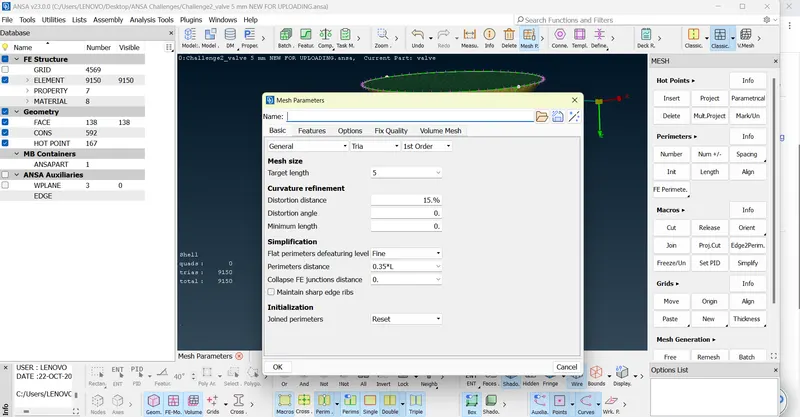
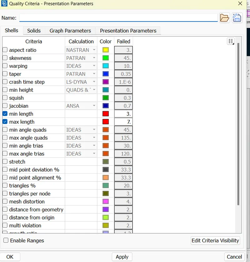
- Select Mesh parameters and set target length as 5mm and Select Quality Parameter and set minimum length as 3mm and maximum length as 7mm.
- Select Mesh deck and and select mesh parameters by selecting CONS of each PIDs and set length as 5mm and select macros and set as 5mm.
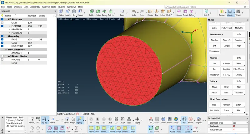
- Now select spot mesh and select face and middle click on mouse to see the meshes.
- Continue for each PID’s by NOT, Neighbour, All, AND, OR options in visibility tab.
CASE2: 3MM TARGET LENGTH
- Select Mesh parameters and set target length as 3mm and Select Quality Parameter and set minimum length as 1mm and maximum length as 5mm.
- Select Mesh deck and and select mesh parameters by selecting CONS of each PIDs and set length as 3mm and select macros and set as 3mm.
- Now select spot mesh and select face and middle click on mouse to see the meshes.
- Continue for each PID’s by NOT, Neighbour, All, AND, OR options in visibility tab.
CASE3: 1MM TARGET LENGTH
- Select Mesh parameters and set target length as 1mm and Select Quality Parameter and set minimum length as 0.5mm and maximum length as 2mm.
- Select Mesh deck and select mesh parameters by selecting CONS of each PIDs and set length as 1mm and select macros and set as 1mm.
- Now select spot mesh and select face and middle click on mouse to see the meshes.
- Continue for each PID’s by NOT, Neighbour, All, AND, OR options in visibility tab.
CASE2: MIXED TARGET LENGTH
- Select Mesh parameters and set target length and Select Quality Parameter and set minimum length and maximum length FOR DIFFERENT pid’S
- Select Mesh deck and and select mesh parameters by selecting CONS of each PIDs and set length and select macros.
- Now select spot mesh and select face and middle click on mouse to see the meshes.
- Continue for each PID’s by NOT, Neighbour, All, AND, OR options in visibility tab.
LEARNING OUTCOME:
- Lifelong Learning
- Modern Tool Usage
- Communication
RESULT:
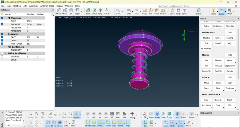
CASE1: 5MM TARGET LENGTH
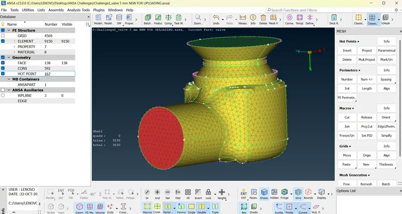
Mesh length= 5mm
Total Mesh elements=9150
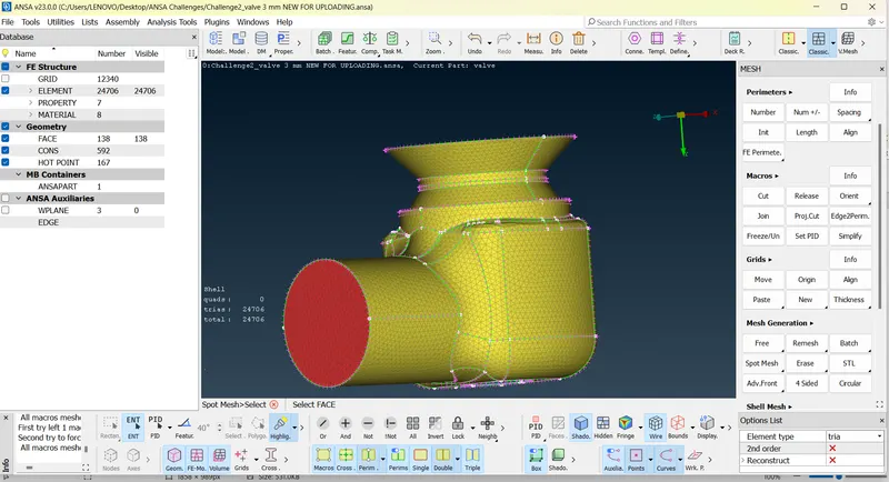
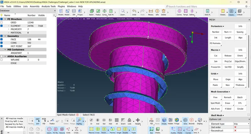
CASE2: 3MM TARGET LENGTH
Mesh length= 3mm
Toltal Mesh elements=24706
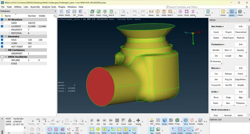
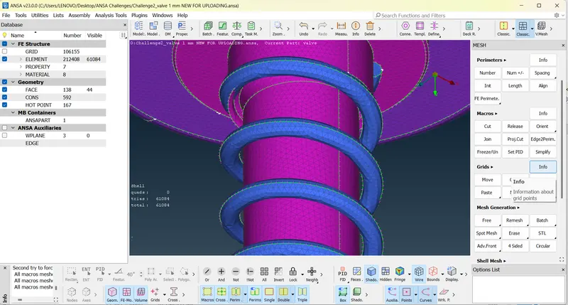
CASE3: 1MM TARGET LENGTH
Mesh length= 1mm
Total Mesh elements= 212408
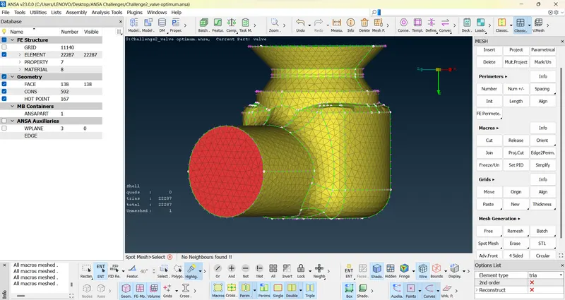
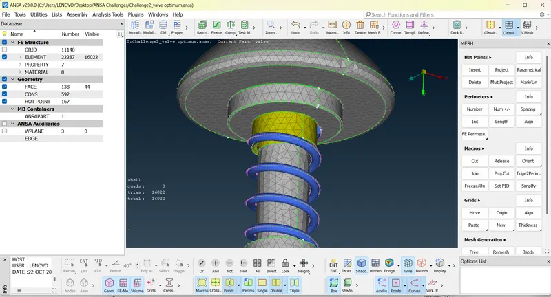
CASE4:MIXED TARGET LENGTH
Mesh length= 1,3,4,5 mm
Total Mesh elements=22287
ALL MODELS ATTACHED GOOGLE DRIVE LINK:https://drive.google.com/drive/folders/1-noIJvWz0WEfUKBhJ-GNsfBPFWugrs_C?usp=sharing
CONCLUSION:
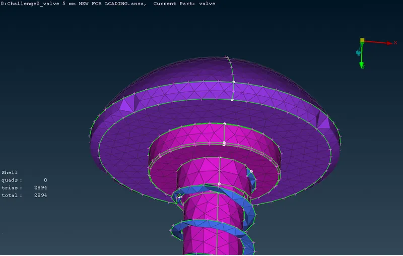
In the case 1 with 5 mm mesh length, it was found that spring and some areas of valve head was found to be distorted.Best results were obtained when mesh sizes were smaller, but increase in mesh elements is not appreciable, so a mix of mesh lengths were used in this project to get best otuputs in case4 study.