Week 2 Challenge : Surface meshing on a Pressure valve
Aim:
Perform surface meshing on Pressure Valve.
Objective:
For the given model, check for the geometrical errors and perform Topology cleanup accordingly. Set three different target lengths as three different cases and mesh the model.
- Target length = 1mm, 3 mm and 5 mm (i.e. 3 cases)
- Element type = Tria
Apply any one target length from the above at a time for the entire model as One case. Submit 3 different models for 3 cases.
Write a detailed report on your meshing process and also mention which case is giving good results along with the reason.
Answer:
Received model.
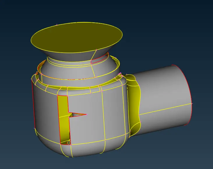
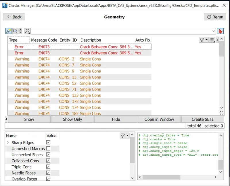
Initial geometry checks.
As it can be seen from the below image that the geometry has total 46 problems. These problems need to be resolved before proceedings ot the meshing.
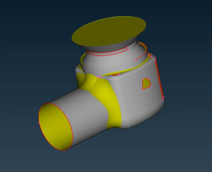
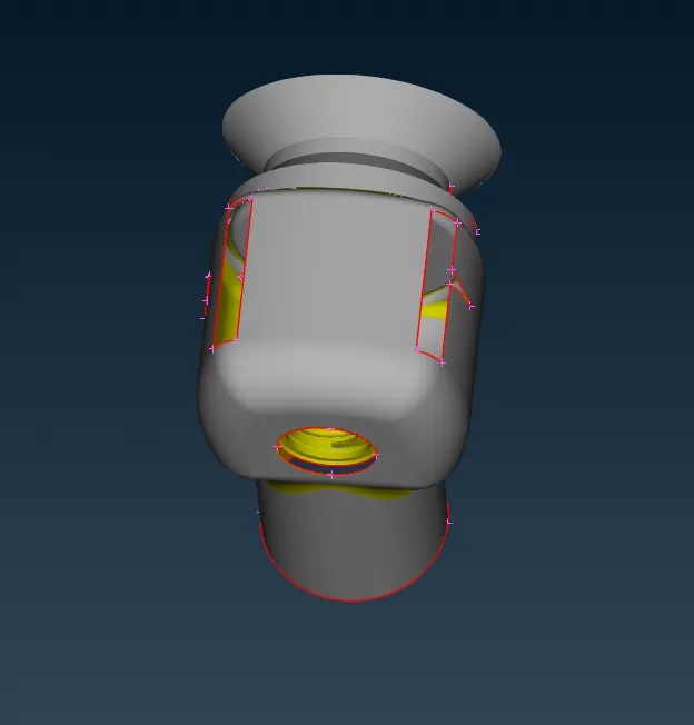
Erros are shown in below model:

Commands from the following toolbars has been used:
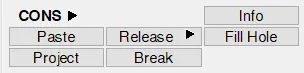
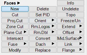
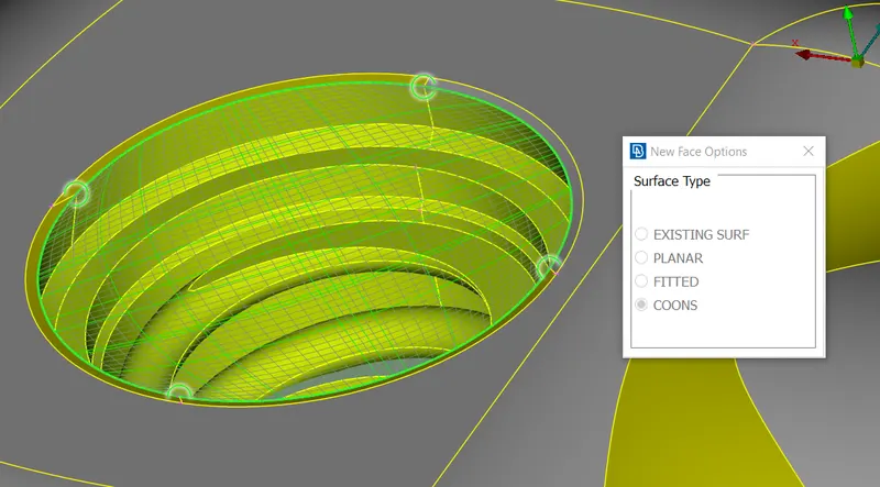
First of all, cracks & missing surfaces has been filled using "New" faces from faces toolbar.
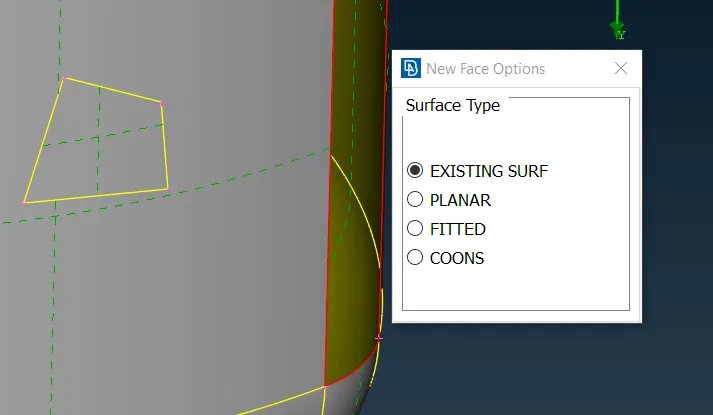
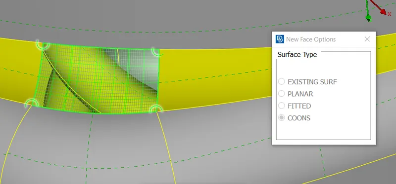
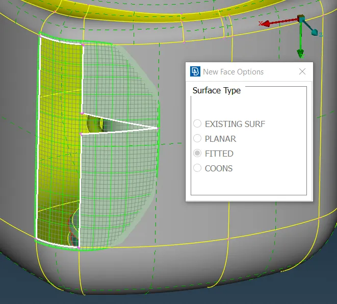
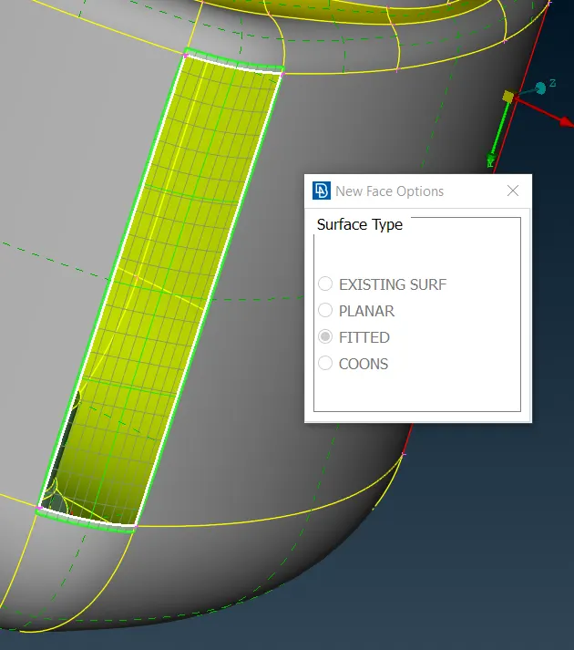
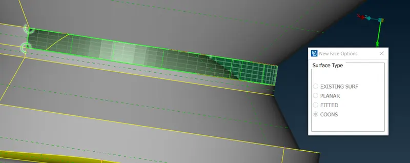
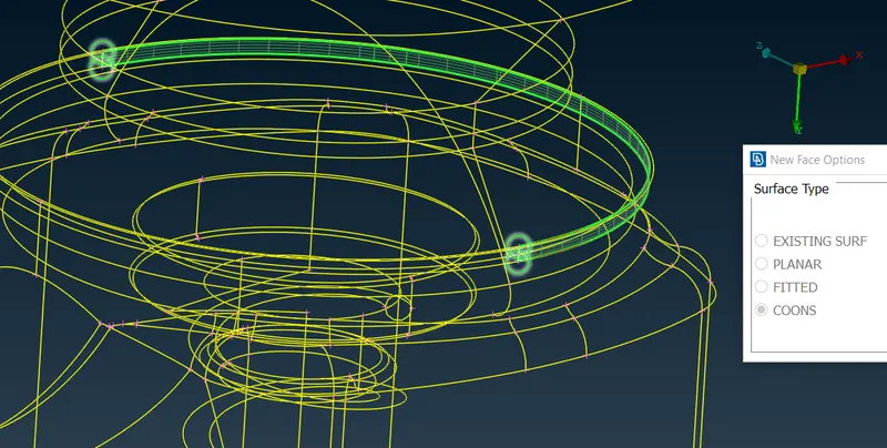
In following case, vertical surface was unable to form by the command if we are using "loop" command to select the CONS. That's why, the surface has been formed in two steps by using "Entity" mode to select similar length of CONS to form vertical surface.
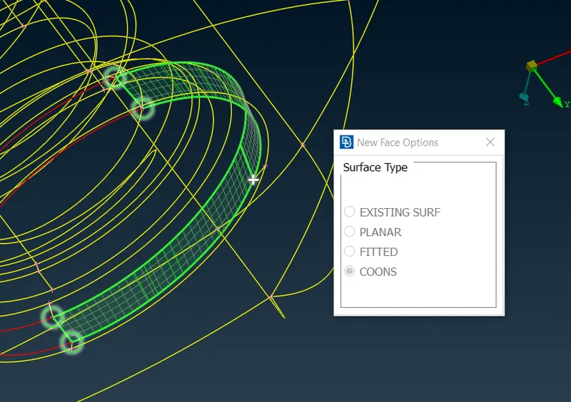
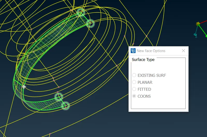
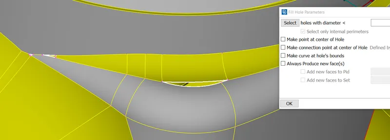
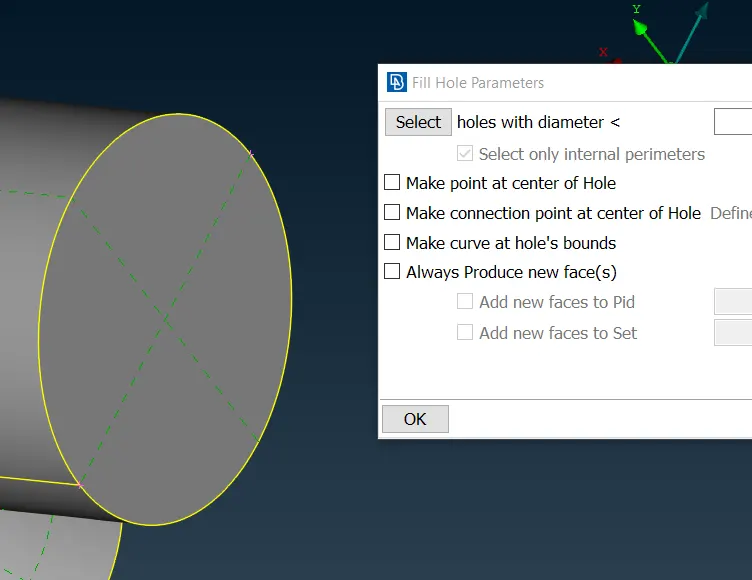
At smaller gaps, "Fill Hole" command has been used to fill the gaps.
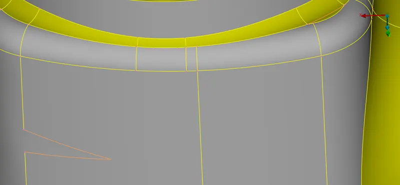
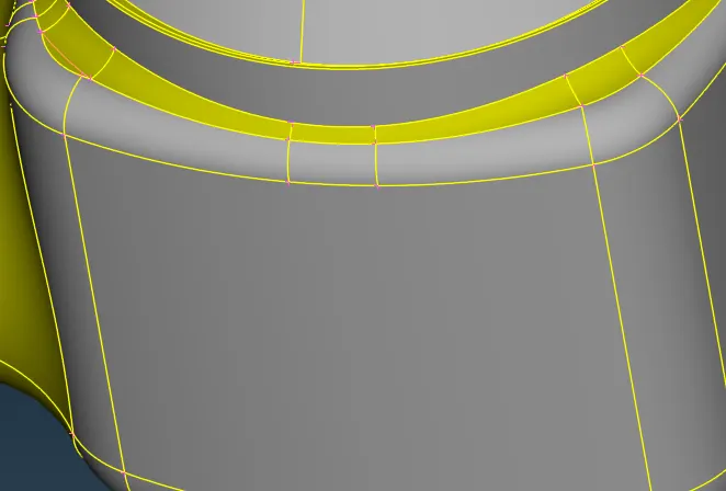
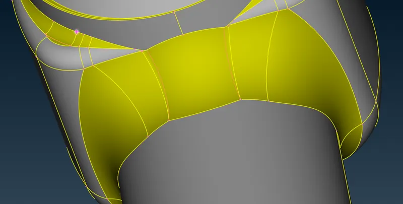
Using "cut" command, unneccessary edges has been removed. These edges might have sizes lesser than the actual element length or they might create the face whose areas are very small compare to mesh element size. In below images, orange color edges are the edges which has been removed.
For CFD application, fluid volume is required to extract from the geometry to perform simulation. To make the close geometry, the Pressure valve has been closed using "Fill Hole" command.
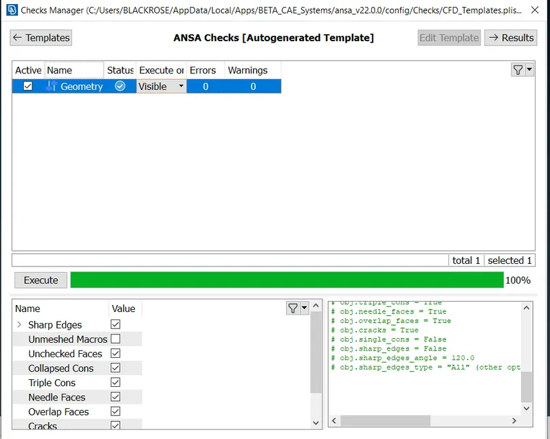
Final Geometry Checks after correcting the problems determined in previosu check.
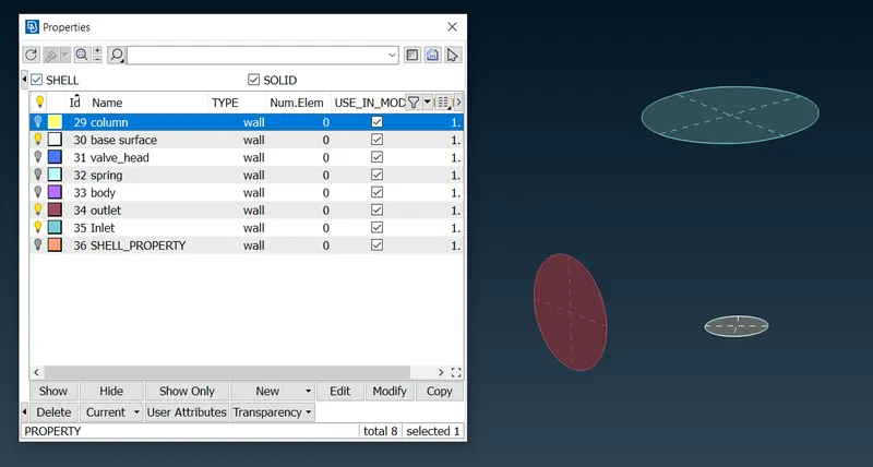
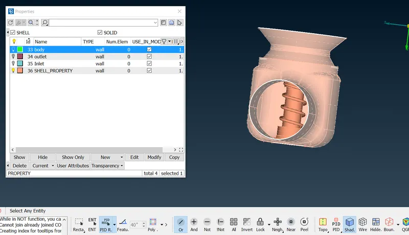
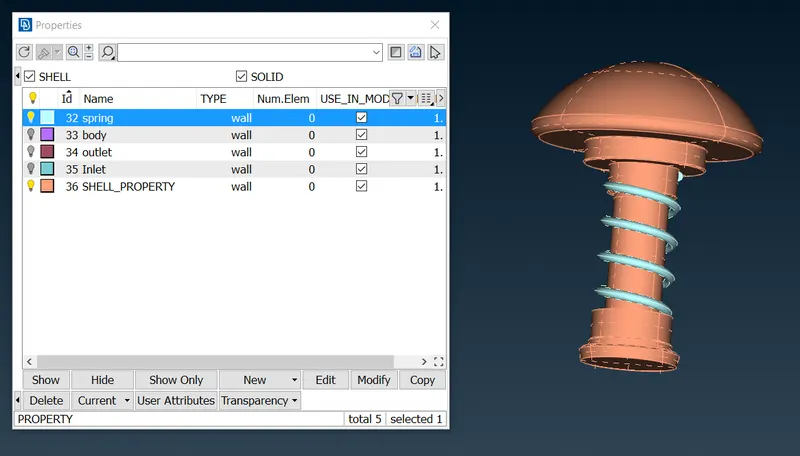
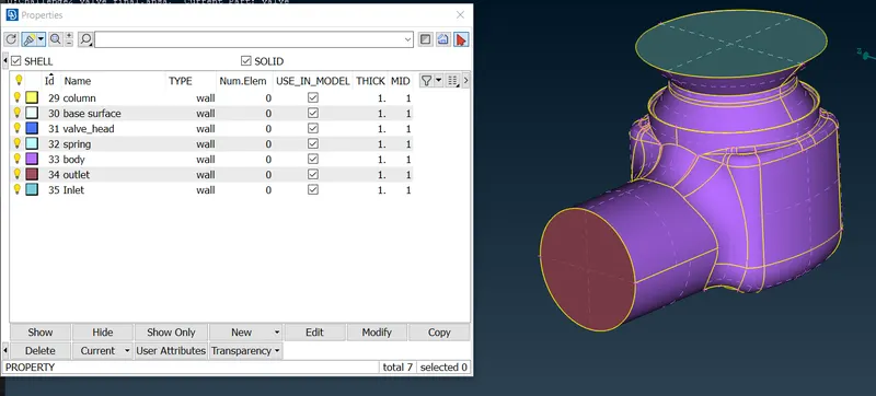
The whole geometry has been divided into different sections like inlet, outlet, body, spring, base surface, column & valve head. In ANSA, this sections has been assigned different PID (Properties ID) to identify them & for easy filtration in later stages of process.
PID for each section has been created in properties toolbar and than apply them to respective faces as shown in below images.
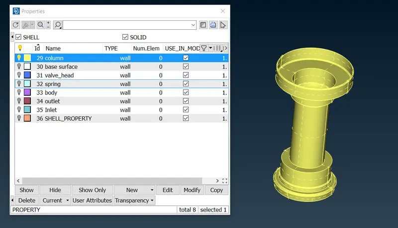
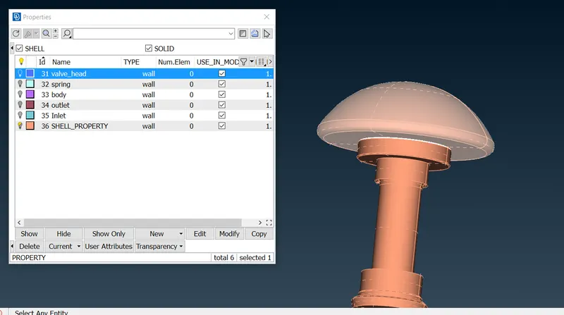
After assigning the seperate PID to each faces, the empty "SHELL_PROPERTY" was tried to remove but the problem has been faced and received following error,
" Selected Id is used by a deleted FACE and cannot be deleted. "
To resolve this issue, the command called "undelete" in faces toolbar has been used. This commad displays the all deleted geomentries from the model as shown in below image.
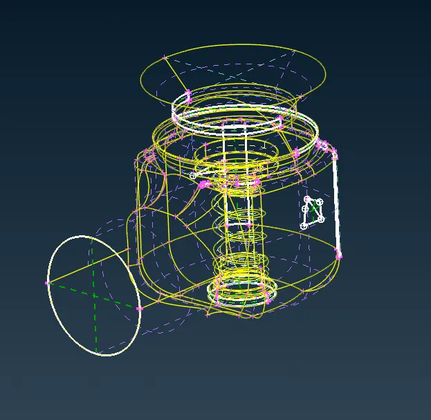
As it can be seen from the above image that the hatch lines have different color than the rest of the magneta hatach lines which indicates that that face might have overlapping face.
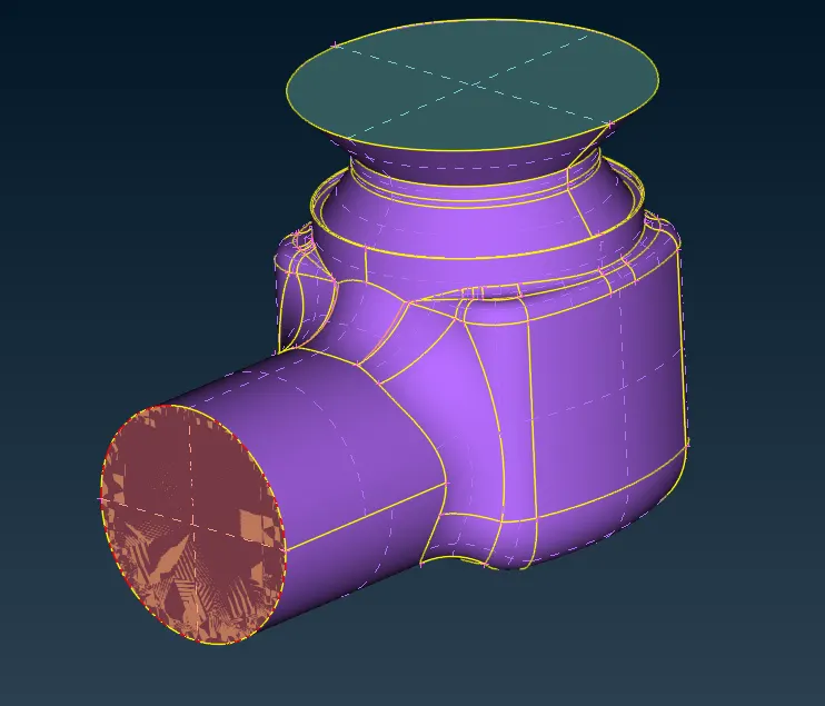
Now the "SHELL_PROPERTY" has been successfully deleted.
After deleting "SHELL_PROPERTY" PID, following message has been published in the info bar.
"24 entities from other decks were also deleted.
31 Items deleted."
At last "Topo" command has been used to reconnect the surfaces.
Final PIDs.
Meshing:
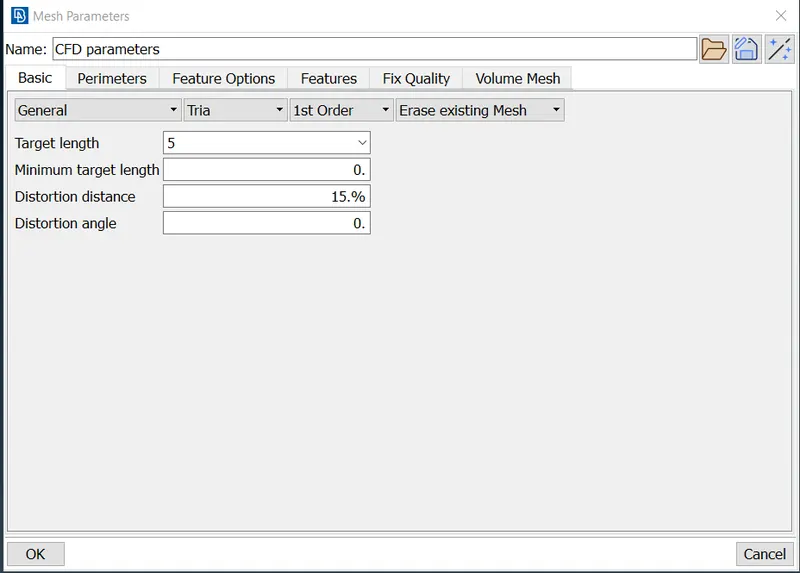
Initially mesh length has been required to enter at four places.
Mesh element length = 5mm
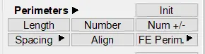
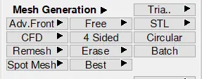
Following toolbar has been used:
Mesh Parameters
Quality Criteria
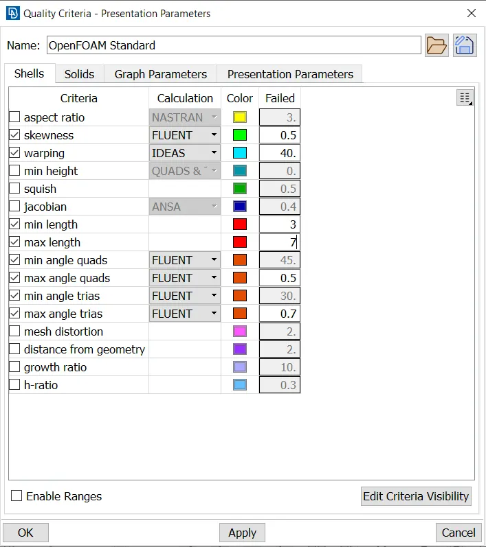
Length command from Perimeter toolbar
Here element length has been entered for both Perimter & Macros in similar way.
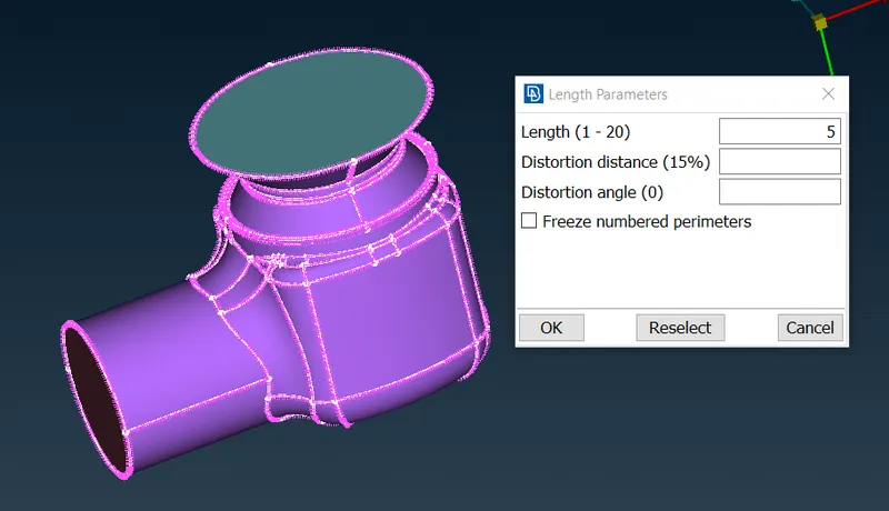
Above steps will be same for all three mesh sizes. The mesh parameters & quality criteria will be set according to following sizes.
- For 3 mm mesh size
min length = 2mm
maximum length = 4mm
- For 1 mm mesh size
min length = 0.5mm
maximum length = 2mm
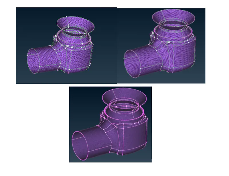
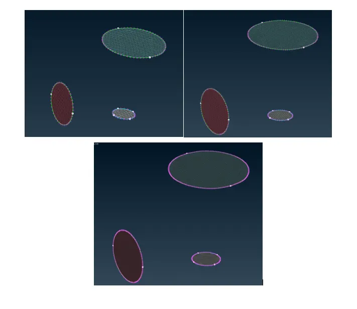
Screenshots has been presented to compare the effect of mesh size on the model.
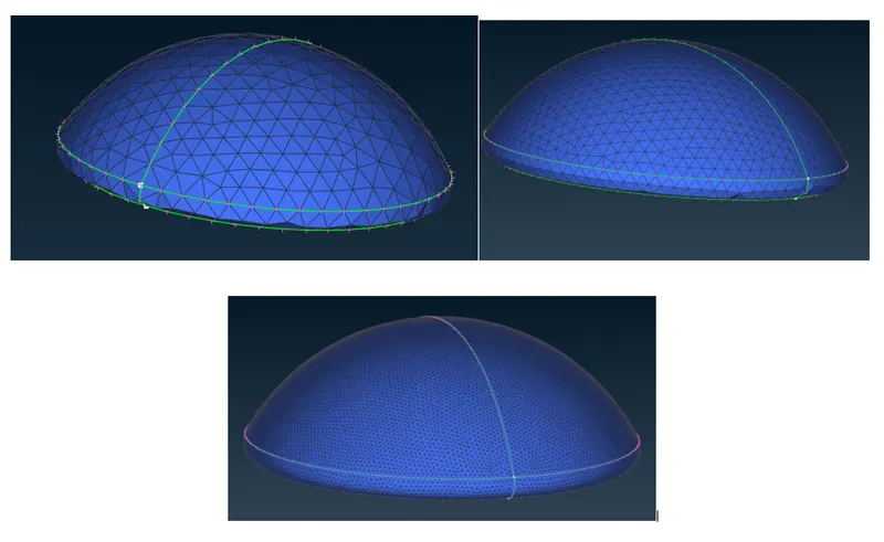
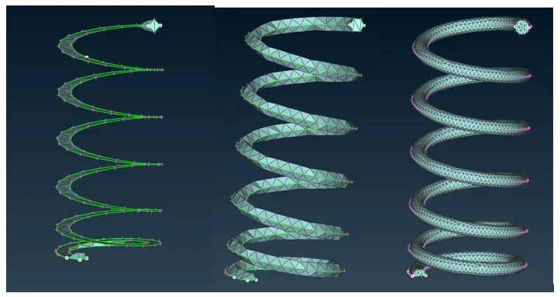
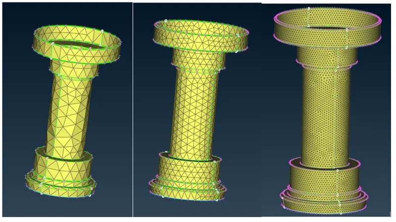
Images has been presented in clockwise direction for 5mm, 3mm & 1mm from top left corner.
Body
Inlet, outlet & Base Surface Mesh
Valve head
Spring
Column
Final Model
For 5 mm
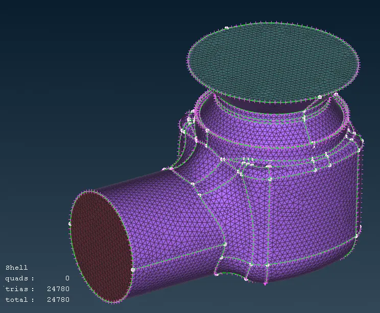
For 3mm
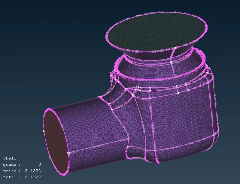
For 1 mm
Number of Elements for each size
| Element Length (mm) | Number of Tria Elements |
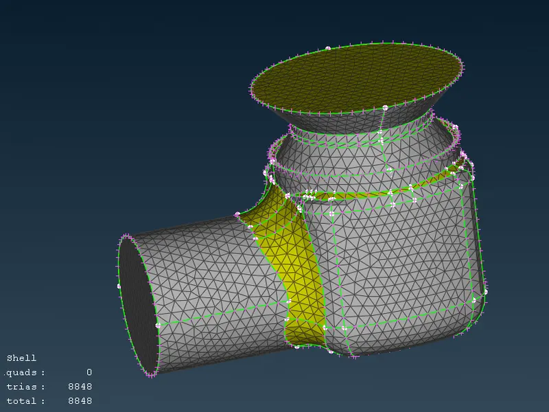
| 5 | 8848 |
| 3 | 24780 |
| 1 | 211522 |
After comparing all three results, the model with 1mm element length has captured details like curvature, fillets more precisely. While the model with 5 mm element length has failed to capture some key details like the shape of the springs or valve head details.
Number of elements for 1mm element size is 211522 comapre to 8848 for 5mm & 24780 for 3mm. More elements means it requires more computer resources & more time to solve the problems which affect the cost of project.