Week 2 Challenge : Surface meshing on a Pressure valve
AIM- To clean the geometry for the surface mesh on a pressure valve with element type tria and mesh lengths of 5mm, 3mm, 1mm respectively by using ANSA.
THEORY
Terminologies or modules used
TOPO-Set of tools for geometry cleanup and setting PID's
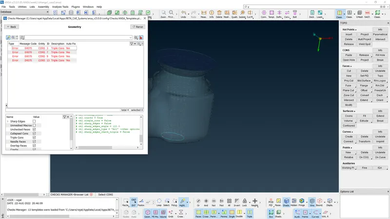
- GEOMETRY CHECK- There is check command in which we choose geometry for checking geometrical errors.
- FILL HOLES- In geometry cleanup the fill holes is used to fill surface gaps.
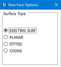
- NEW FACE- It's also geometry cleanup module which has 4 options for surface gap filling .
- PROPERTIES(PID's)- We use this to assign PID's for face or surface for creating different PID's and also giving it colour and other properties.
MESH- To generate Surface mesh or 2d-Mesh
- MESH PARAMETERS- We use this to give minimum & maximum lengths of mesh and also determine type of element in this case its tria .
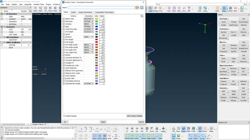
- MESH QUALITY-We use this to determine mesh properties and qualities to determine mesh.
- PARAMETER- We assign element lengths in this case 5mm,3mm& 1 mm.
- SPOTMESH- We use this to generate CFD mesh.
STEPS & MODEL
1. Import CAD model
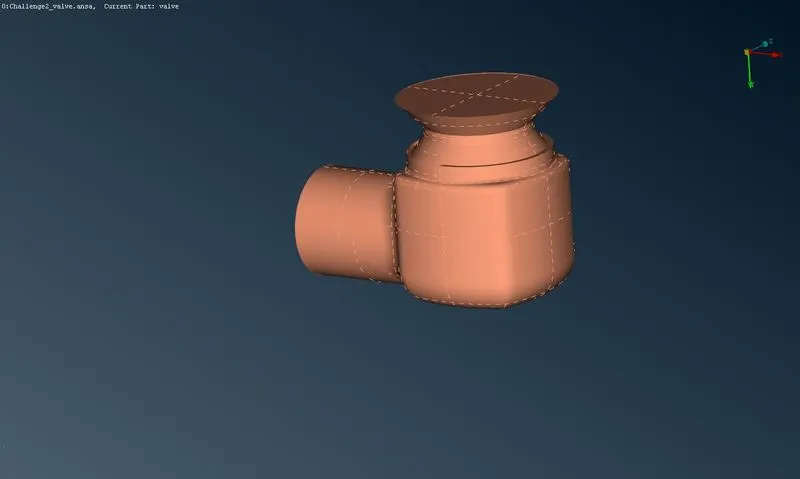
We import valve file which contain errors.
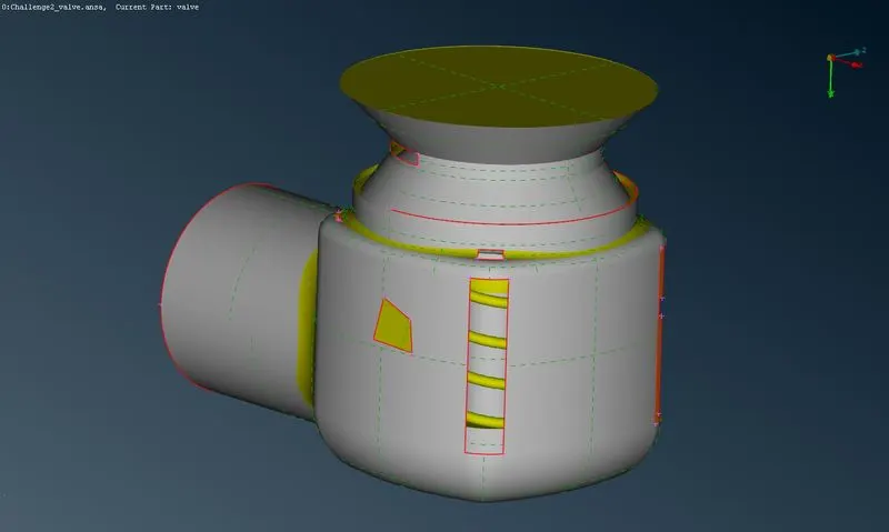
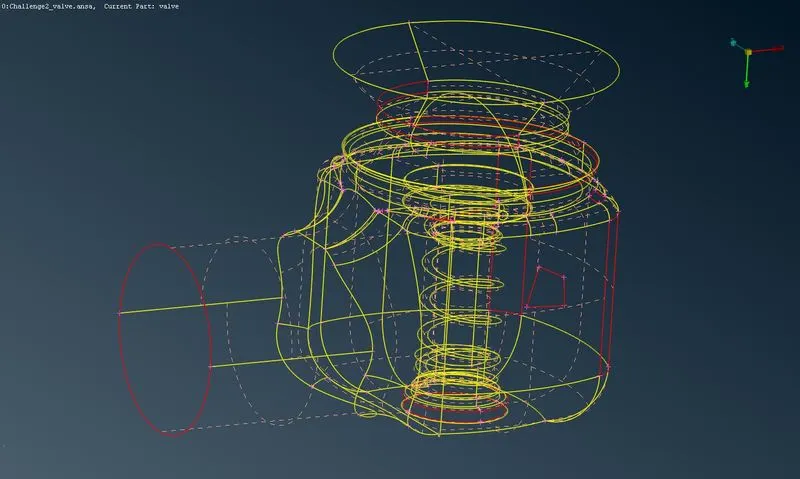
As we can see in both SHADOW MODE & WIREFRAME MODE the red cone or single cone is shown considered as errors . We need to resolve this error in geometry cleanup. The exact can be found in geometry check mentioned in next step.
2. Geometry checkup
We go to Check option in toolbar and click Geometry to execute any errors in geometry when we click it shows error as below
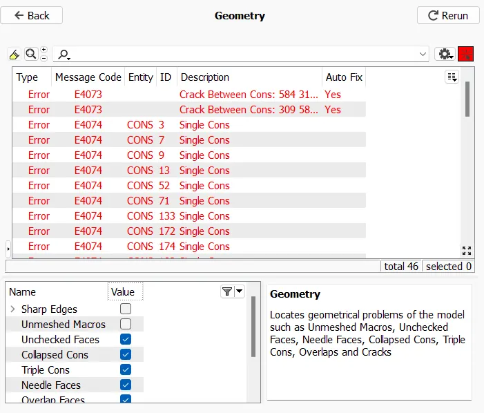
These all errors need cleanup which we will be doing in next step.
3. Geometry Cleanup
We will clean geometry by choosing red cones step by step or via check bar results .
We can also click to switch off the double cons and tripl cos so only single cons is visible.
After finding the cones we can fill gaps or create surface using 2 commands
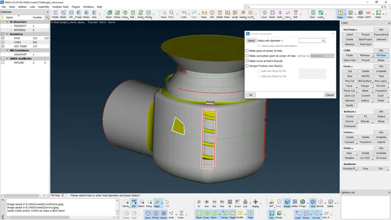
1. Fill holes.- We click at fill holes and choose red cons and middle click or enter to fill holes.
2. New(faces)- Here we click the new icon then selct cons via entity , PID's etc and middle click or enter to execute the surface filling.
Solved body after errors
IF we run check again it only shows one triple con which can't be considered as error as we need to fill the holes to make body enclosed as we want CFD solutions so this triple cone created is neccesarry.
4. Setting Relevant PID's
For setting up new PID's we need to open properties then right click and select new and create shell and enter name accordingly.
Then we right click on name and click on apply and select surface we wanna use for PID's
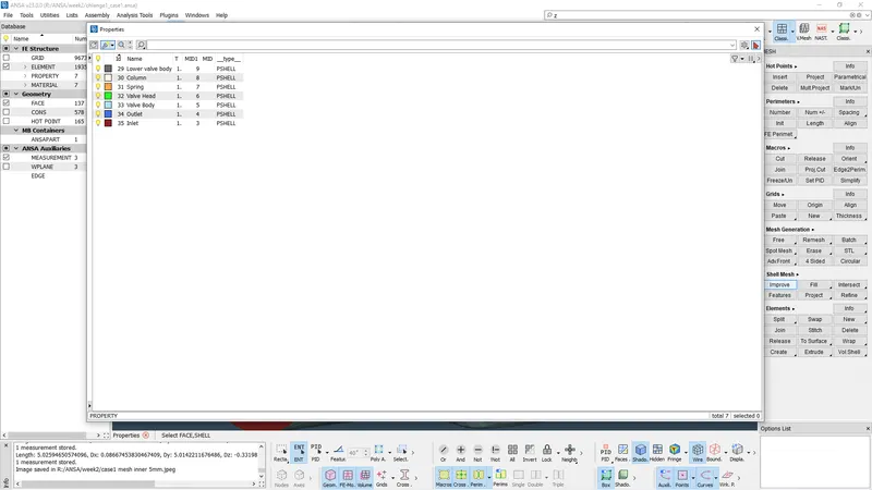
Also we assign different colours so it can be easy to determine.
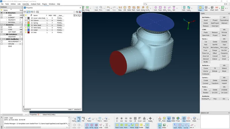
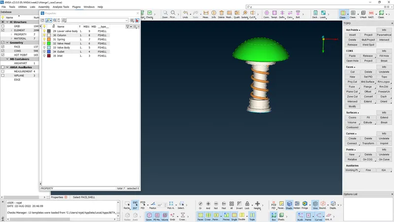
Yellow light in property index shows which PID's is visable and grey shows which is invisible.
5. Defining size and length of element
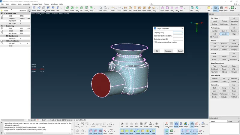
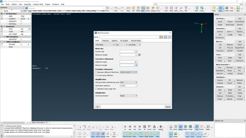
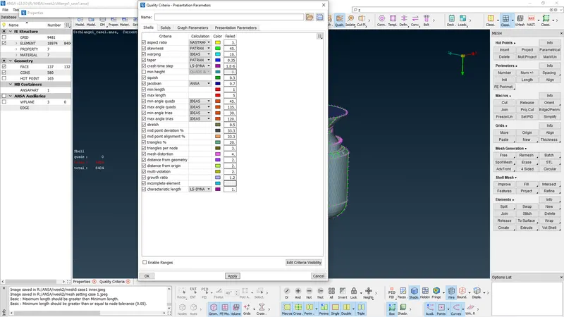
We determine mesh quality and length for differnet case 5mm ,3mm, 1mm etc using mEsh parametere, Mesh quality command & Length command
for example
6. Selecting mesh type and generating mesh
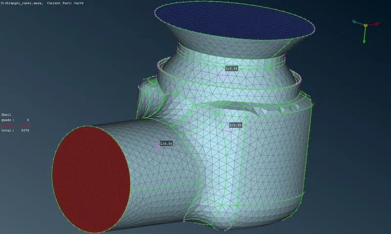
CASE 1 = 5mm
Parameter length is selcted as 5mm and mesh parameter min & max lengths are given accordingly as shown above.
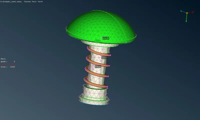
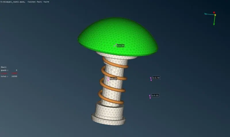
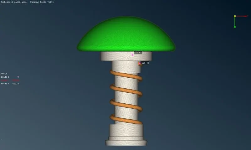
For spring in all case the mesh parameter is selected as 1 mm because the dia is approx 2.5mm if we use mesh parameter of 3mm or 5mm it will show flat surface .
Then we use spot mesh to create the mesh for 5mm.
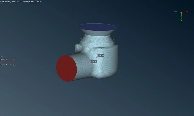
CASE 2= 3mm
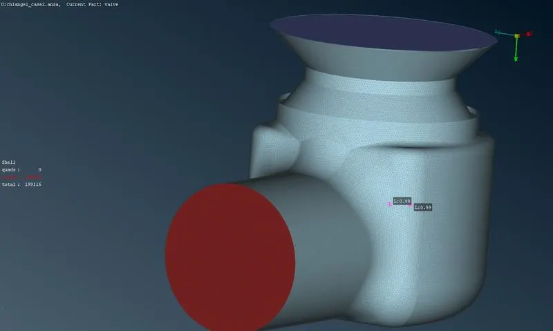
CASE 3 = 1MM
CONCLUSION
- We can observe that as the mesh length decreases from 5mm to 1mm the no. of element increases .
- It is because we are decreasing distance between each nodes.
- So, The more no. of elements better is mesh quality and it takes longer for simulation even if its by fraction.
- For 1mm mesh length the elements are most than 5mm mesh length .Benifit of more elements is that it will capture the geometry in much more detailed and specific ways as we can see there is error in geometry for 5mm near the curvatures but for 1mm length the curvature geometry is fine and smooth.
LINK
https://drive.google.com/drive/folders/12Sjai2dI2EPmxzJdRvv4jFqQn0zyUNJS?usp=sharing