Week 2 Challenge
1.1)answer:
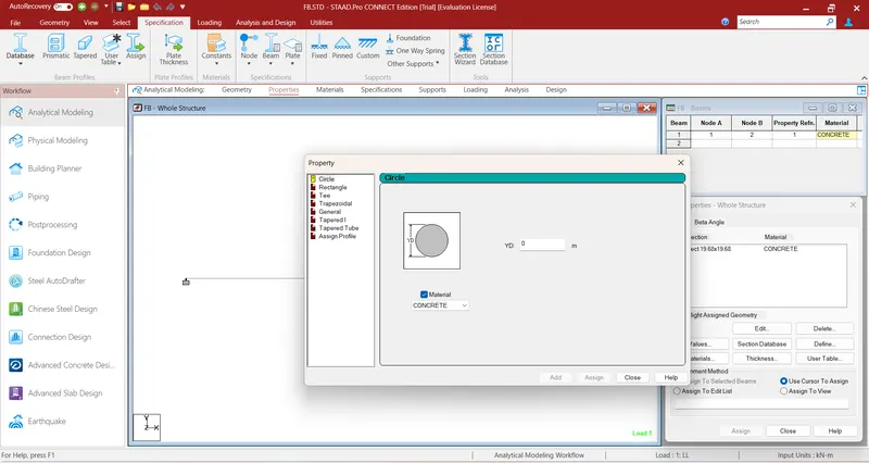
Go to properties in that select define property select circle and give the radius for the member and assign the defined circle to the member created
1.2)answer:
-
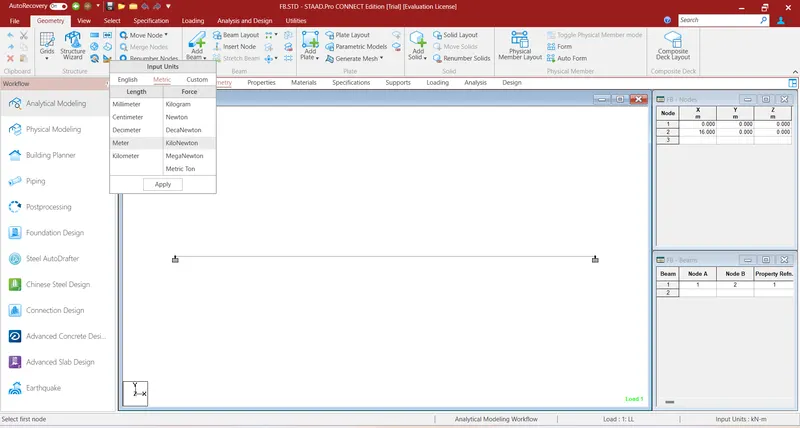
While creating a model go to unit system and assign the units Go to geometry in that’s elect input units and assign the units ,Go to view menu in that select display options in that select structure units
1.3)answer:
-
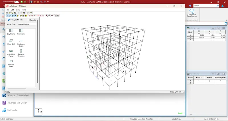
Go to geometry tab in that select structural wizard in that select frame model in that select bay frame ,Give the parameters like length, height, width, No. of bays along length, No. of bays along height and No. of bays along width
1.4)answer:
- Euro code, ACI, IS code
1.5)answer:
- In design select materials as concrete and select the code and then go to define parameters and select FC then specify the value
2.1)answer:
Steps involved in RCC design are,
- Geometry
- Properties
- Materials
- Specification
- SupportLoading
- and Load combinations
- Analysis
- Design
2.2)answer:
- When the fixed type of support is specified, for those degrees of freedom which are to be treated as fully restrained, STAAD assumes the displacements to be known quantities whose value is zero. Hence, these degrees of freedom are not considered for the stiffness matrix and their value is not calculated When the enforced type of support is specified, for those degrees of freedom which are to be treated as restrained, STAAD assign a spring with a spring stiffness – translational stiff springs for translational restraints and rotational stiff springs for rotational restraints. Those degrees of freedom which are free to displace are assigned springs of zero stiffness. Hence for all the 6 degrees of freedom at such supports, the displacements are calculated. The one which have a stiff spring with end up having a negligible displacement and those with zero stiffness springs will have a displacement based on the structure geometry, properties and loading
3.1)answer:
- Read or study drawings (Plan/Elevation/Section)
- Input Geometry
- Input Properties
- Input Specifications/Constants/Supports
- Run analysis
- Specify analysis type
- Input design standards
- Input load and load combinations
- Verify results
- Design
- Represent design as document and drawing
3.2)answer:
- Node by node method
- Grid method
- Structural wizard method
3.3)answer:
- Fixed support
- Pinned support
- Fixed but support
- Enforced support
- Enforced but support
3.4)answer:
- Create the staircase by using the nodes in the geometry panel After creating the nodes assign the plate elements as the slab property after that define load cases and calculate the area load acting on the staircase and apply load cases and load combination to the staircase slab and then create a mesh on the plate element
- After that run the analysis and go to post processing mode and click on plate result option in that select stress distribution result and choose the stress type accordingly and that stress distribution result is displayed Maximum and minimum stress values are displaced
3.5)answer:
- After completing the design and running the analysis software will provide the BMD and SFD
- After the analysis click on Post processing mode and click OK
- Go to deflection command and click on beam result
- In reaction command click the beam deflection
PRACTICAL:
A)
AIM: To analyze the simply supported beam by STAAD Pro.
PROCEDURE:
- Open the new STAAD.Pro file
- Create the nodes in geometry tab as per the question
- Go to geomerty tab select add beam and draw the beam by usinf beam cursor
- Go to properties tab and select define and give the rectagular dimensions for the beam
- Select the created beam and assign the rectangular property to the beam
- Go to material tab give the materialas concrete
- As per the question load P is located at 5m from each support
- Go to geometry tab and add nodes at 5m and 15m
- Go to support tab and create a enforced but supportand click on add and add the support to the beam using node cursor
- Go to loading tab add the load cases
- Assign the loads to the beam using use cursor to assign
- Go to analysis tab and select analysis command and do perform analysis
- Run the analyis
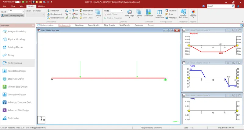
RESULT: I understand the how to analyze the given member by STAAD pro.
B)
AIM: To analyze the fixed beam by STAAD pro.
PROCEDURE:
- Open the new STADD.Pro file
- Create the nodes in geometry tab as per the question
- Go to geomerty tab select add beam and draw the beam by usinf beam cursor
- Go to properties tab and select define and give the rectagular dimensions for the beam
- Select the created beam and assign the rectangular property to the beam
- Go to material tab give the materialas concrete
- Go to support tab and create a fixed support and click on add and add the support to the beam using node cursor
- Go to loading tab add the load cases
- Assign the loads to the beam using Assign to selected beam
- Go to analysis tab and select analysis command and do perform analysis
- Run the analyis
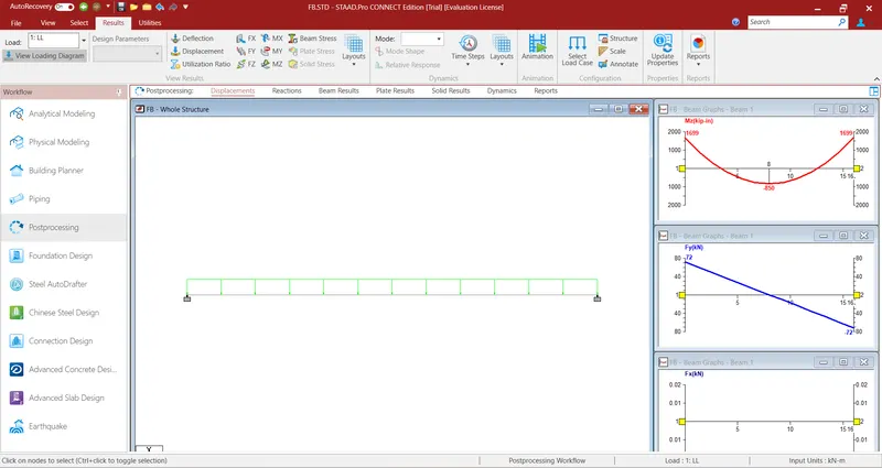
RESULT: I understand the how to analyze the given member by STAAD pro.