Week 2 Challenge
1. Creating Column Pedestal Properties and modeling in software
In order ro create Column Properties, we hae to go to the option of "Manage Propoerty Sets" in the top toolbar as shows in picture below

After this tab opens , to define the new property of any structural member, click on "New" > "Member" and select the member type that we want to define. In this case we have to define the property of concrete column first.
In steel Structures , the Steel Column rests on Concrete column/pedestal which trhansfers the load to foundation. The Size of steel column should be selected on the basis of a few factors
1) Basic judgement on the basis of column layout
2) Span between column
3) Loading on the structure
4) Type of building (Industrial,commercial,residential)
5) Column location in layout.
To define the Column Property the process is shown in image below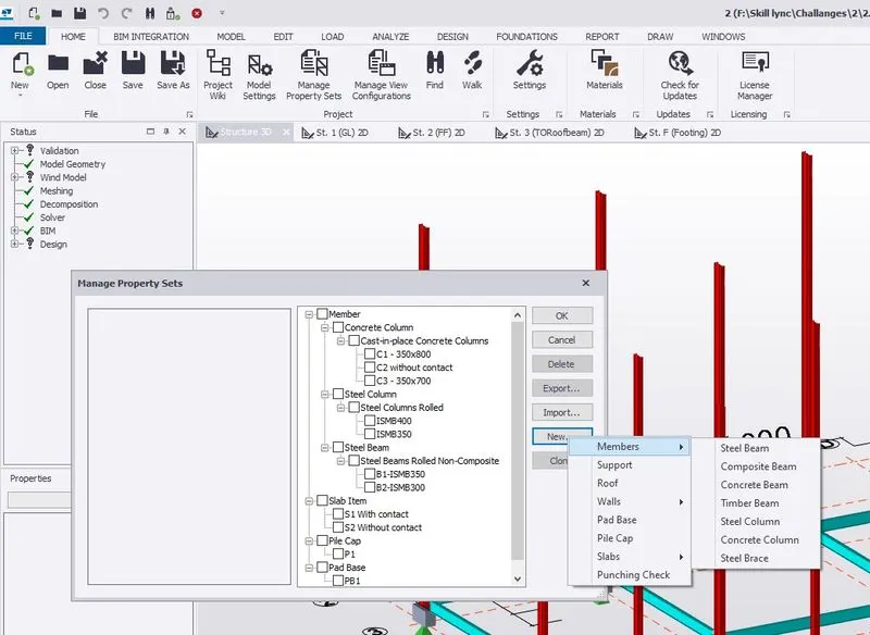
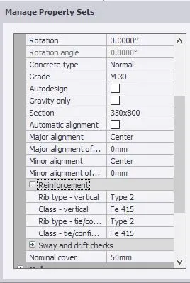
After selecting the option to define Concrete/Steel Column, another tab opens to define various properties e.g. Grade of material , section type and size , releases , cover , bar dia etc as shown in image
From the study and observation of plan two type of column are fixed. The size of Concrete column should be more than the steel column to accomodate the steel column and base plate.
To model the column in the in software, click on model tab as shown in image

After we click the option of column in concrete section, another dialogue box opens in properties tab where we have to select from the predefined column properties and define bottom and top level of column as shown below
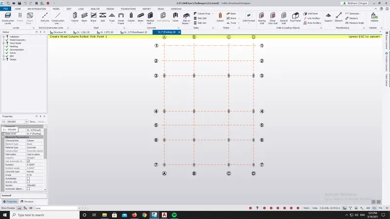
After fixing these properties we have to go on the plan at particular floor (for concrete pedestal, it is Foundation level) and start clicking on the points where we want to place the column .
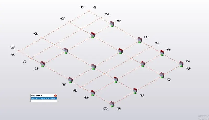
After Placing the column , 3D view can be checked as shown here
2. Creating Steel Column Properties and modelling of column above concrete Pedestal
To model steel column, the procedure is almost same . Instead of going for concrete column we have to select the option of defining steel column properties as shown below
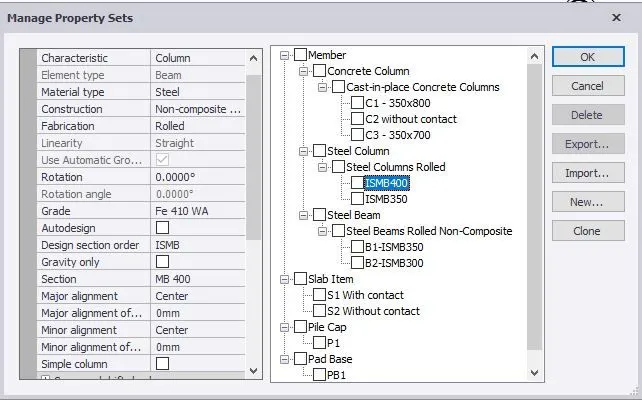
While defining steel column properties, we have to fix the Material grade (Fe290/410 etc) . The option of Auto Design shall be unchecked for every member. After selecting from various sections (I-section, Channel , angle) the section size is to be fixed. Here for Column I section (ISMB) has been choosen. Now the steel column is to be modeled above concrete column pedestal by clicking on the column location in Plan of respective floors.
Releases - The Steel concrete joint shall be assigned as pinned joint and the top of steel column is to be assigned as fix joint.
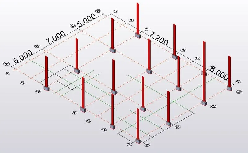
The 3D view after modelling concrete column is shown below
3. Creating Beam Properties and assigning primary and secondary beams on Floor
In order to create beam properties , the process is same as of column . This time we have to select the option to define steel beam. Just as the case of steel column, to model the steel beam the material grade, section type and size is to be defined as shown below. The initial assumption of beam size usually depends on the load coming from slab and the span of the beam. Here we have selected two sections to start with.
Alignment - It is an important aspect in beam model. It gives us the option to place the beam at different location with respect to column axis and levels.
For example, when we want to model the beam below floor the Major alighment of beam shall be selected as TOP. And when we model ground floor beams we can select the major alignment option as BOTTOM.
Primary Beams are those which extendds from column to column and those beams which rests on beam (on one end or both ends) are considered as secondary beams. The Secondary beams are useful in dividing the slabs in shorter area , which increases the stability of structure and reduces the deflectoin. Also , the secondary beams are provided where the wall load is present.
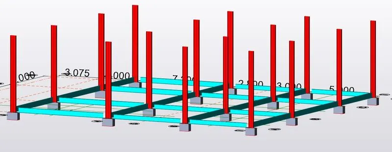
To model the Primary beam on plan, select the option to model beam in steel section. Select the beam property from pre-saved sections and model the beam by conecting two columns with cursor. after joing the columns with primary beams, the 3D view looks as shown below
To model Secondary Beams, the location of the beam should be selected in such a way that the the effective span of slab is reduced. The beam should be modeled in shorter direction. If there is any wall load on slab, the beam can be modeled in it's location below. If there is no wall load, the slab can be divided in equal parts. To fix the beam position, construction line can be modeled by taking offset from pramary beams.
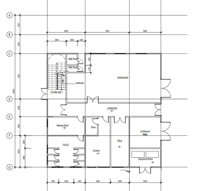
Plan of the ground floor is attached below. with reference to tha plan and internal arrangement the secondary beam position is marked and is modeled in the structure.
To model the Beam, we have to go the option of modelling steel beam and load from presaved properties as shown below
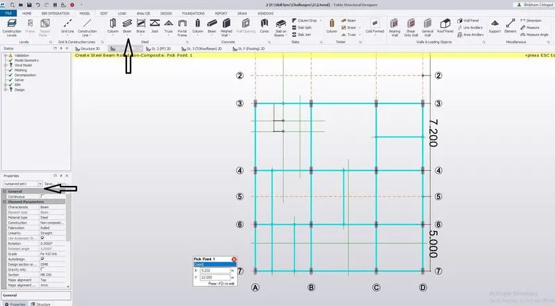
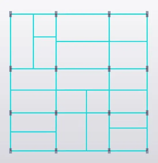
From the understanding of the plan and internal arrangement, beams are modeled and is shown in image below
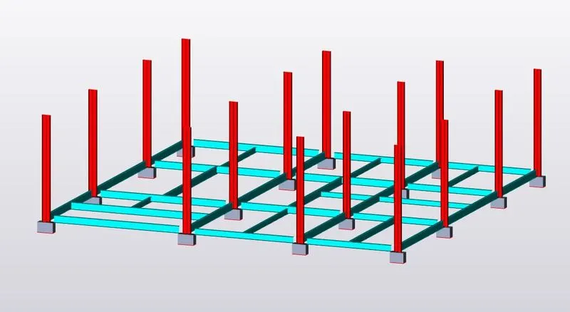
Validation - This is one of the most important tool in modeling , analysis, and design of any project . This helps us in finding the error and rectifying it. In order to keep the process smooth and get proper results , it is always recommended to use the tool often.