Week 3 Challenge
1. Creating Beam Properties for first floor and modeling
The procedure for Beam property modeling at any floor is same. The only thing it differs is the placement of beams for different floors. The firstfloor plan is attached below.
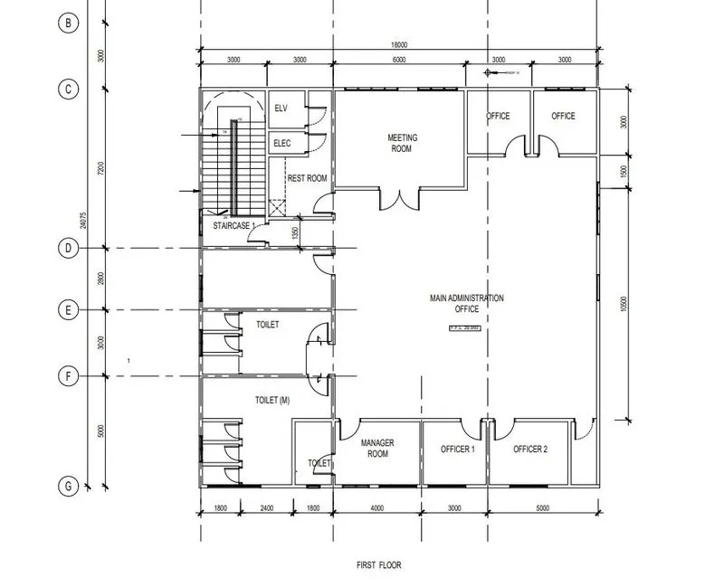
In order to model the beam for this floor, first the plan is to be studied carefully and potential beam position is to be marked. The beams should be in the combination of primary and secondary . Primary beams are the ones which connects column to column ans the secondary beams are used below the walls (line load) and to divide slabs into smaller effective spans. Based on the knowledge the beam position marking is shown here
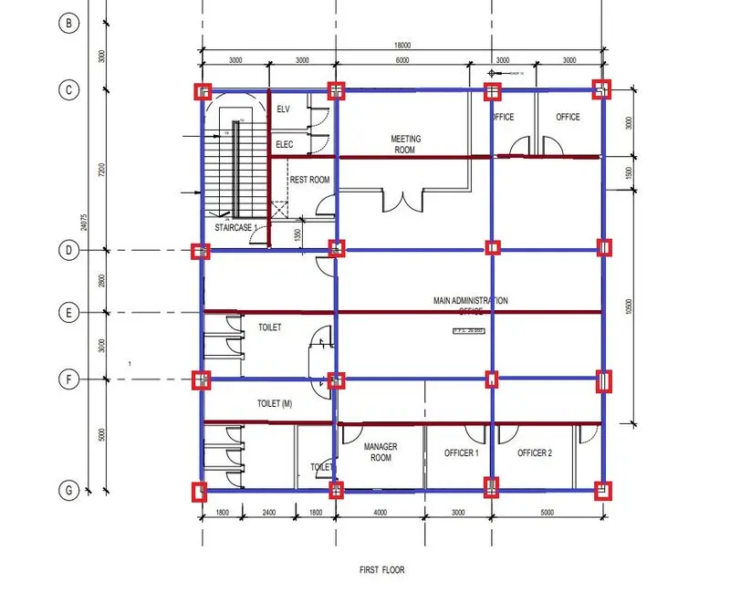
As seen from the image, the Beams marked with Blue colour are primary beams and are directly resting on columns. Beams marked with Brown colour are secondary beams.
Note: The beam size should be selected in such a way that the depth of secondary beam should not be more than the primary beam on which it is resting.
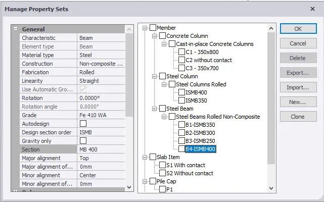
The Beams section is taken as ISMB and the depth of section is choosen from few aspects such as Span of beam, Imposed load on beam, beam position and the Type of building. depending on these factors , four type of section depth are considered here to start with. Later after analysis we can change the section size to make the structure safe as well as economical.
In order to create beam properties ,we have to select the option to define steel beam in the "Manage Property Sets" Tab. To model the steel beam the material grade, section type and size is to be defined as shown below.
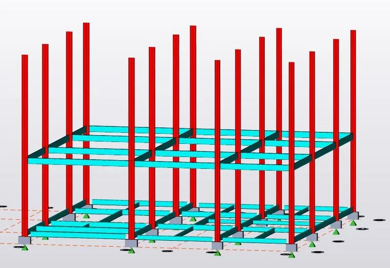
To model the Primary beam on plan, first go to the respective floor and select the option to model beam in steel section. Select the beam property from pre-saved sections and model the beam by conecting two columns with cursor. after joing the columns with primary beams, the 3D view looks as shown below
To model the secondary beams on floor, we should model the construction line to fix the position of secondary beams. From the study of plan, the construction line marking is shown below.
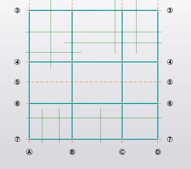
The procedure to model secondary beams is similar to primary beams. Here the beam will rest on beams as shown below
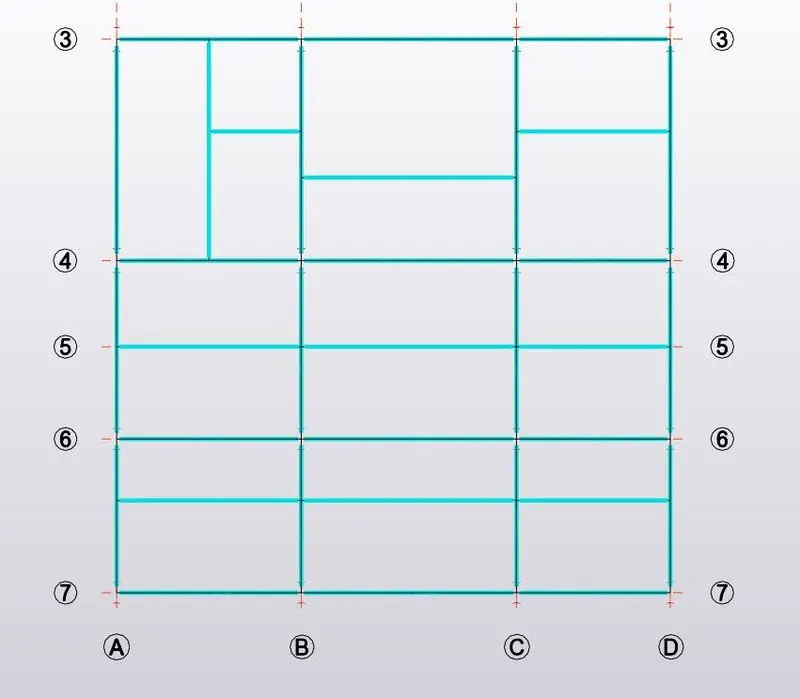
After Modeling the beams on First floor , it is required to run the Validation to check and rectify the errors, if any. The warning after validation can be seen in the "Status" Window on the left side as shown below
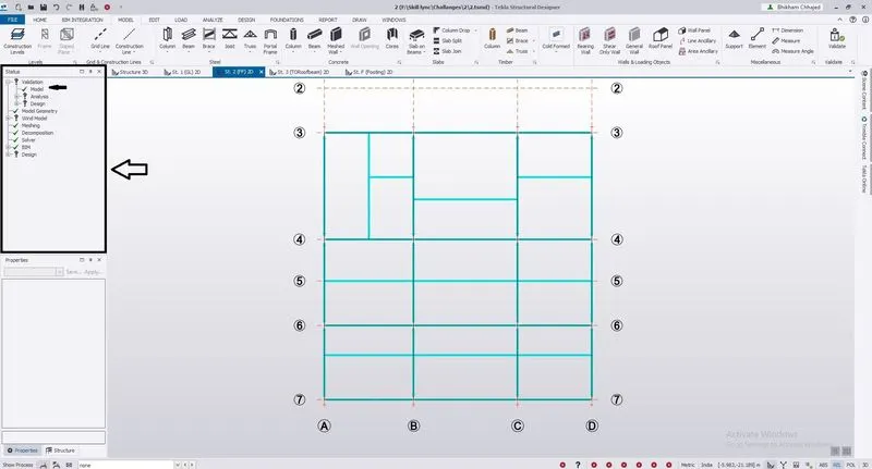
If the Program doesn't shows any error, we are good to proceed further.
2.a Creating Rafter Beam on Second floor and assigning Joint restraints
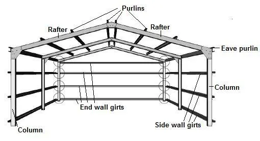
In Industrial steel structure , Rafter beam is an integral part. It is a sloping structural member which connects the crown of shed with the eaves (ends). This is used to support roof of shed. The roof sheet rests on purlins and the purlins rest on rafter. This can be understood with the following image
To model the rafter in software, we need to have front/side elevation of structure. In order to get the elevational view, we take the help of "Frame" tool. It can be accessed from the "Model" tab as shown below

In order to access this tool, the model is to be in 3-D view. Once we click on the "Frame" tool , we have to select the Grid lines along which we want to create sectional elevation. Once we click on the particular Grid line, it creates sectional elevation, as shown below
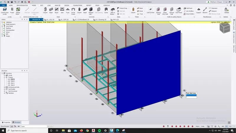
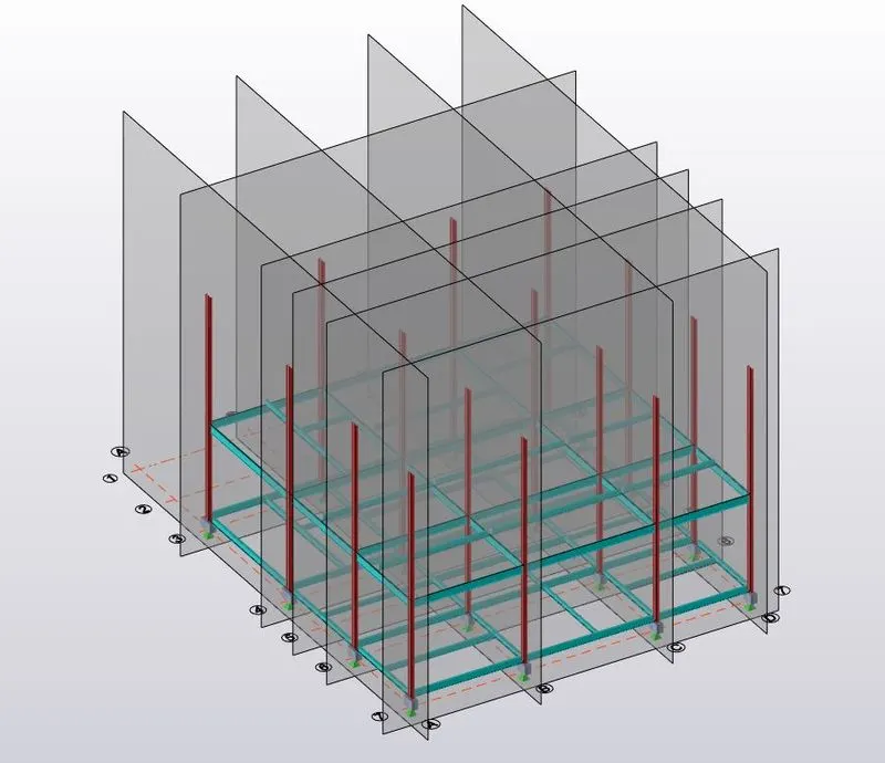
After selecting different Grid lines one by one, the Frame planes are shown below
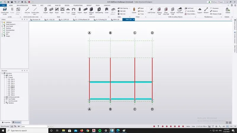
The Elevational view for Grid 7 is shown below
In order to get the crown point , we have to refer the sectional view of the building that is attavhed below
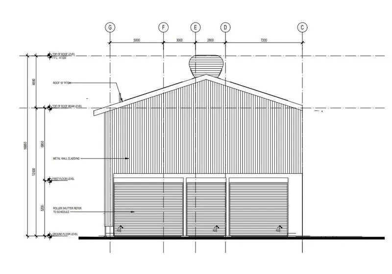
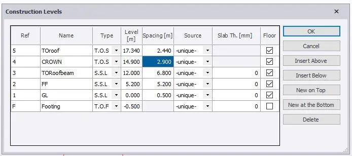
Now, the Slope is given as 18 degree and considering the crown at the center of the building we can calculate the height of crown above Roof level. From rounding the calculation is came as 2.9m above top of roof level. This level is added in construction level as shown below
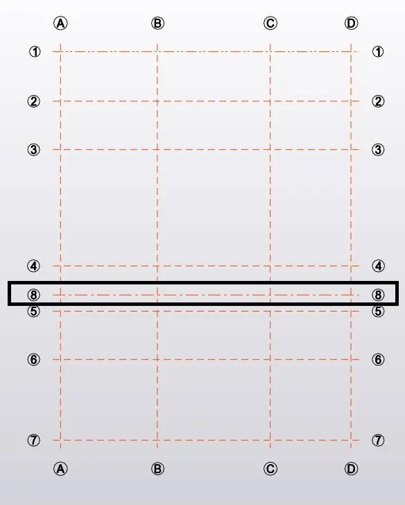
Now, to mark the center position on plan , another Grid line is created at center as shown below
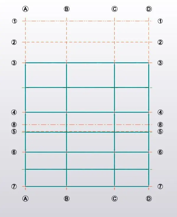
Before modeleing the Rafter beam the, floor beams at roof level is to be modeled. The process is similar as modeling the First floor beams.
Since it has to carry just its own weight and no other extra floor load, small beam sections can be choosen. Slab area is divided into half with the help of secondary beams
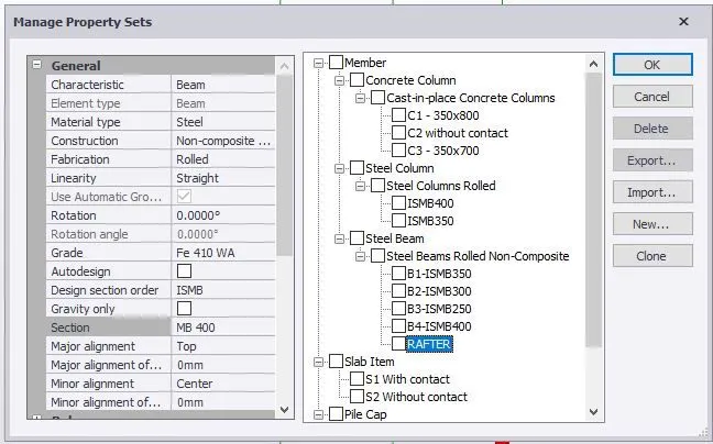
To model the rafter beam, the beam property is created first as "Rafter" from the Manage Property sets tab as shown below
After defining the beam property, we have to go in the sectional elevation to model the Rafter . Click on the option of modelling steel beam and draw sloped member by connecting column at eave level with the crown. This process is to be done on both side of the crown.
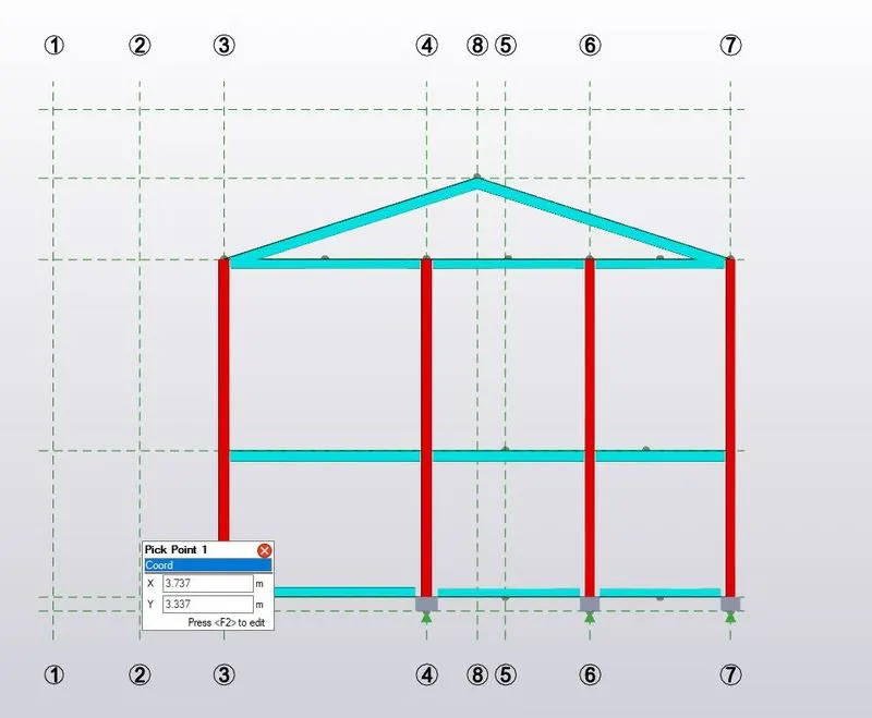
After modeling the rafter beam on one grid frame, the end constraint of the rafter beam is to be defined. We have to define the connection as "Moment Frame Connection". This type of Connection is used to transfer the moments and uses Rigid Connection between the members.
For this , we go to 3-D view and click on the member, after this a property window will open and we have to go to the option of "Releases" . To make the member fixed on both ends the end constraint is to be selected as "Fully Fixed" as shown below.
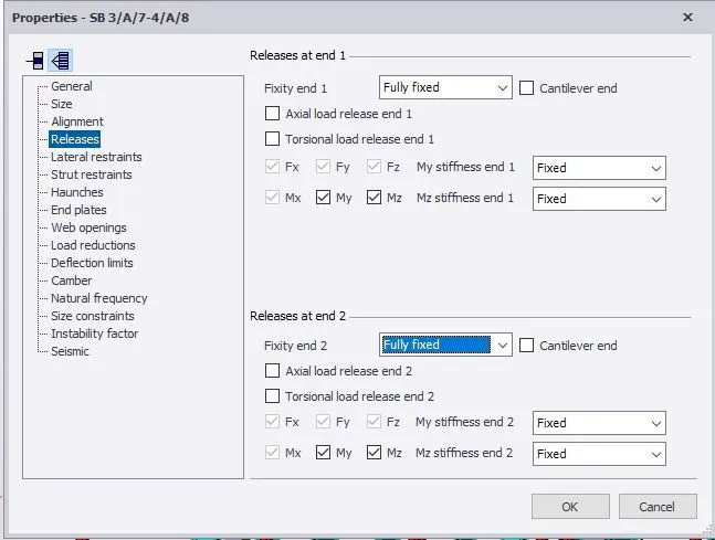
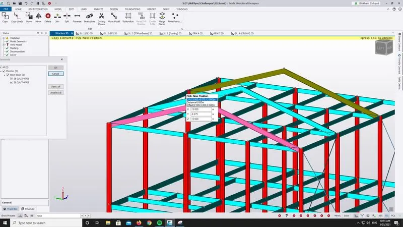
Once we model and define restraints of rafter beam on one grid, we have to replicate the same for other grids also. For this we can use the help of "Copy" command of "Edit Menu". Select the member to be copied and click on the copy command. Pick up the reference point and click on the other points where we want to paste the members. The updated view is shown below
Click on the "Validation" tab to chech the errors , if any
2.b Modeling and placing bracings in Structure
Bracings - In order to increase the stability of structure against lateral loadings and to transfer the lateral loadings properly, the bracings are used. Bracings are usually of two types e.g. Vertical and Horizontal (depending on the plane in plane in which they are used). Vertical bracings are used in vertical planes to tie columns, it can be of different type i.e. X-type, K-type, V-type etc. Bracings should be placed in such a manner that almost every column gets connects through it on either side. Preferably the bracings are to be provided at extreme ends first then at other suitable position, it can be placed.
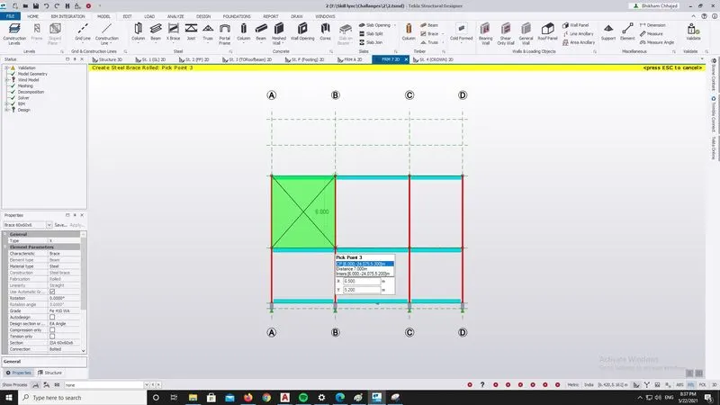
Before modeling the bracings, we have to define property. To define the property we have to go the "Manage Property Sets" tab and select the option to define Steel brace under the member section. Angle sections are suitable as braces, so, equal angle section of 60x60x6mm has been choosen.
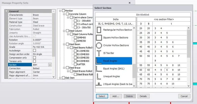
To model the bracings , go to the elevational view and click on the option to model X-brace, select the property from saved sets and model the brace by clicking on the four corners as shown below
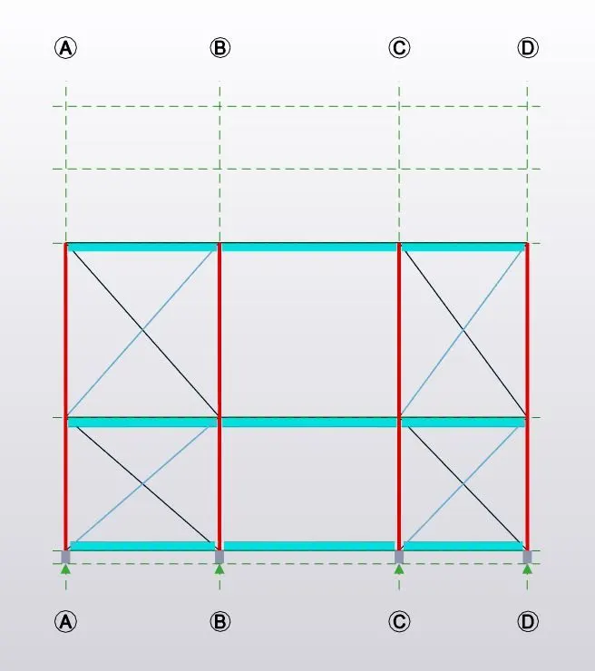
Similarly , the bracings can be modeled for other grids.