| LOADS |
CLAUSE |
DEFINITION |
| 1. DEAD LOAD |
203 |
The dead load carried by a girder or member shall consist of the portion of the weight of the
superstructure (and the fixed loads carried thereon) which is supported wholly or in part by
the girder or member including its own weight. |
| 2.LIVE LOAD |
204 |
204.1 Details of I.R.C. Loadings
204.1.1 For bridges classified under Clause 201.1, the design live load shall consist of
standard wheeled or tracked vehicles or trains of vehicles as illustrated in Figs. 1 to 3 and
Annex A. The trailers attached to the driving unit are not to be considered as detachable.
204.1.2 Within the kerb to kerb width of the roadway, the standard vehicle or train shall be
assumed to travel parallel to the length of the bridge and to occupy any position which will
produce maximum stresses provided that the minimum clearances between a vehicle and
the roadway face of kerb and between two passing or crossing vehicles, shown in Figs. 1 to
3, are not encroached upon.
204.1.3 For each standard vehicle or train, all the axles of a unit of vehicles shall be
considered as acting simultaneously in a position causing maximum stresses. |
| 3. WATER CURRENT FORCES |
210 |
210.1 Any part of a road bridge which may be submerged in running water shall be
designed to sustain safely the horizontal pressure due to the force of the current.
210.2 On piers parallel to the direction of the water current, the intensity of pressure shall
be calculated from the following equation:
P = 52K\/
where,
P = intensity of pressure due to water current, in kg/m^
V = the velocity of the current at the point where the pressure intensity is being
calculated, in metre per second, and
K = a constant having the following values for different shapes of piers illustrated
in Fig. 7
i) Square ended piers (and for the superstructure) 1.50
ii) Circular piers or piers with semi-circular ends 0.66 |
| 4.EARTH PRESSURE |
214 |
214.1 Structures designed to retain earth fills shall be proportioned to withstand pressure
calculated in accordance with any rational theory. Coulomb's theory shall be acceptable,
subject to the modification that the centre of pressure exerted by the backfill, when considered
dry, is located at an elevation of 0.42 of the height of the wall above the base instead of 0.33
of that height. No structures shall, however, be designed to withstand a horizontal pressure
less than that exerted by a fluid weighing 480 kg/m^ All abutments and return walls shall be
designed for a live load surcharge equivalent to 1 .2 m earth fill.
214.2 Reinforced concrete approach slab with 12 mm dia 150 mm c/c in each direction
both at top and bottom as reinforcement in M30 grade concrete covering the entire width of
the roadway, with one end resting on the structure designed to retain earth and extending for
a length of not less than 3.5 m into the approach shall be provided. |
| 5.TEMPERATURE |
215
|
Daily and seasonal fluctuations in shade air temperature, solar radiation, etc. cause the
following:
a) Changes in the overall temperature of the bridge, referred to as the effective
bridge temperature. Over a prescribed period there will be a minimum and a
maximum, together with a range of effective bridge temperature, resulting in loads and/or load effects within the bridge due to:
1) Restraint offered to the associated expansion/contraction by the form
of construction (e.g., portal frame, arch, flexible pier, elastomeric
bearings) referred to as temperature restraint; and
ii) Friction at roller or sliding bearings referred to as frictional bearing
restraint;
b) Differences in temperature between the top surface and other levels through the
depth of the superstructure, referred to as temperature difference and resulting
in associated loads and/or load effects within the structure.
Provisions shall be made for stresses or movements resulting from variations in the
temperature. |
| 6.SEISMIC |
219
|
219.1 Applicability
219.1.1 All bridges supported on piers, pier bents and arches, directly or through bearings,
and not exempted below in the category (a) and (b), are to be designed for horizontal and
vertical forces as given in the following clauses.
The following types of bridges need not be checked for seismic effects:
a) Culverts and minor bridges up to 10 m span in all seismic zones
b) Bridges in seismic zones II and ill satisfying both limits of total length not
exceeding 60 m and spans not exceeding 15 m
219.1.2 Special investigations should be carried out for the bridges of following description:
a) Bridges more than 150 m span
b) Bridges with piers taller than 30 m in Zones IV and V
c) Cable supported bridges, such as extradosed, cable stayed and suspension
bridges
d) Arch bridges having more than 50 m span
e) Bridges having any of the special seismic resistant features such as seismic
isolators, dampers etc.
f) Bridges using innovative structural arrangements and materials. |
2.how to decide the boreholes location and its depth of exploration in case of shallow foundation? What all the parameters we need to get from the site/geotechnical investigation for design of the foundation.
Ans-: Borehole-:A borehole is deep vertical hole with small diameter drilled into the ground to obtain soil samples for soil investigation required for the construction of suitable foundation for the planned structure. It is required to carefully plan boreholes so as to obtain required information with minimum possible cost.
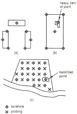
Following are the procedure for setting up borehole layout for site investigation:
- Selecting location and layout of boreholes
- Deciding number of boreholes
- Depth of boreholes
Deciding Number of Boreholes for Site Investigation
The number of boreholes required for a thorough investigation of the given site is difficult to determine because it is affected by several factors such as time allocated for investigations, cost, the structure for which the investigation is conducted and sometimes the availability of necessary equipment and individuals with adequate skills and experience.
Determining Depth of Boreholes
The depth of boreholes is controlled by the depth of the soil that is under the influence of bearing pressure of the foundation. The recommended borehole depth is equal to one to three times the width of the loaded area. This is because it is suggested that bearing pressure below this depth would cause detrimental effect on the structure. If the shallow strip foundation is considered with considerable spacing, then deep boreholes would not be required as shown in Figure
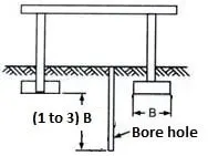 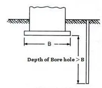 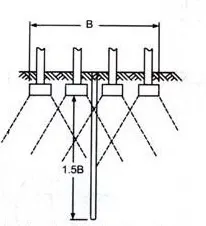
Strip Foundation Large Raft Foundation Influence of footing on soil(raft)
Following are some of the general information obtained through primary site exploration.
- Approximates values of soil's compressive strength.
- Position of the groundwater table.
- Depth and extent of soil strata.
- Soil composition.
- Depth of hard stratum from ground level.
- Engineering properties of soil ( disturbed sample)
different type of soils/rock
Sand
Sandy soils are formed from rock such as shale, granite, quartz and limestone. Sand is the largest of all soil particle types. As a result, sandy soil is loosely packed and very free-draining. Sand does not retain water well and allows air to freely circulate through it.
Silt
Silt is one of the most fertile types of soils and is highly prized by gardeners. Quartz and other necessary plant minerals are present in silt, which is finer than sand but still drains well. Silt has the capacity to both absorb and release water, keeping the soil moist but not wet.
Clay
Clay is made up of very fine soil particles making it very dense. Wet clay is very sticky, while dry clay is hard and difficult to work. Clay soils are tightly packed, allowing very little water drainage or air flow.
Loam
Loam soil is a mixture of clay, sand and silt soils. Because of the mixture, it's considered to be the best for planting.
Sedimentary
Sedimentary rocks are considered "secondary" rocks because they often are made up of pieces of other rocks. Igneous rocks in the crust of the earth are sometimes covered by a thin layer of loose debris and sediment that gets compacted together to form sedimentary rocks.
Shallow foundations are used when the soil is very good or the loads are light and generally consist of fairly light-weight structures, such as footings, raft foundations or simple strengthening of the surface soil (compaction, reinforced earth etc.). Otherwise, deep foundations are required.
|