Week 2 Challenge
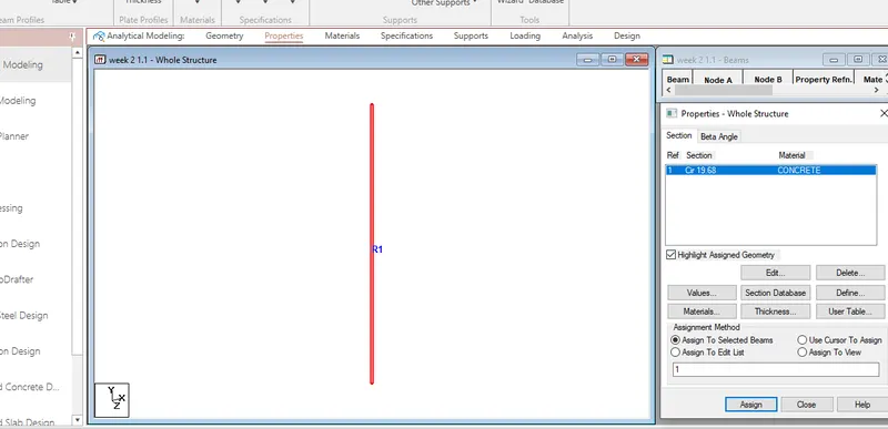
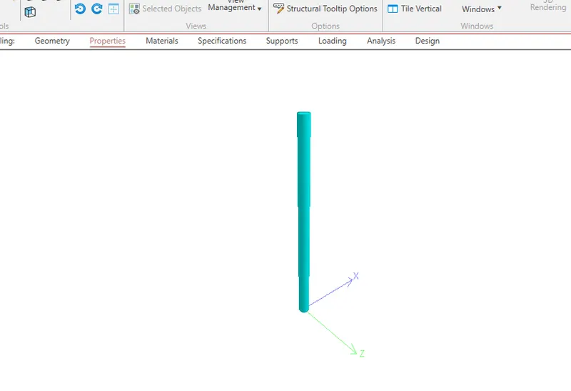
1. 1. How will you assign Circular section to column?
- Open STAAD.pro software
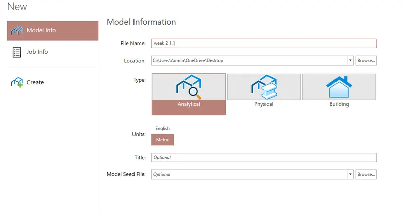
- Create a new model
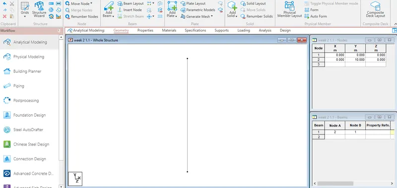
- Mark the nodes with 10m gap in Y axis
- Join the nodes by Add beam option
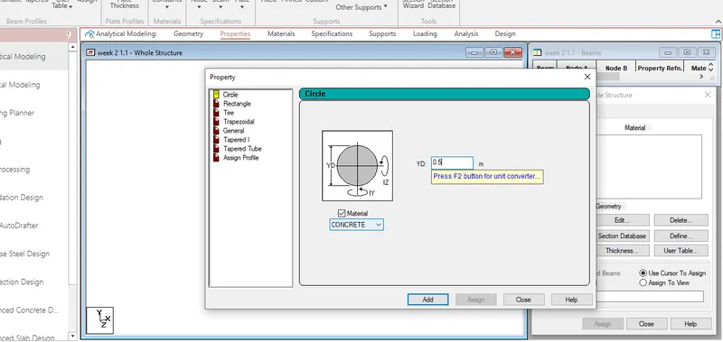
- Now, click on properties
- Seelect define parametersas circular column of 500mm radius
- Assign the circular shape to column
2. How will you assign Unit system to a .std model file?
- First of all, even if we have modelled in metric units, we can still get the data displayed in imperial units
- To do that, we just need to, Go to view - Display option and set appropriate units for structure units, section units, force units etc as needed
- The model data will be displayed graphically in those units
- Also, to ensure that any data going forward is entered in imperial units, we can go to tool> set current input units and set length and force units appropriately.
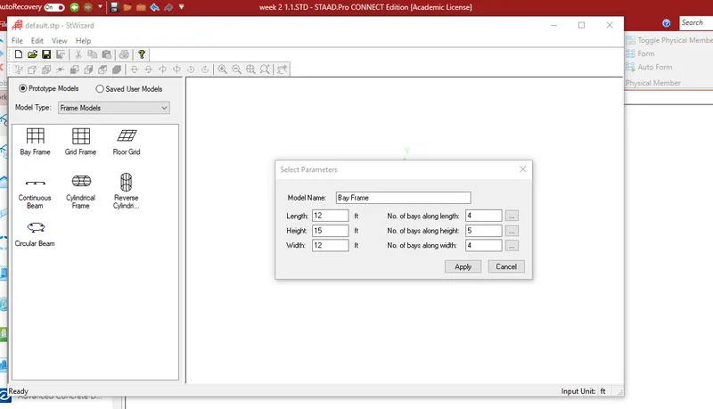
3. What are the parameters to be specified while using “Bay Frame” option?
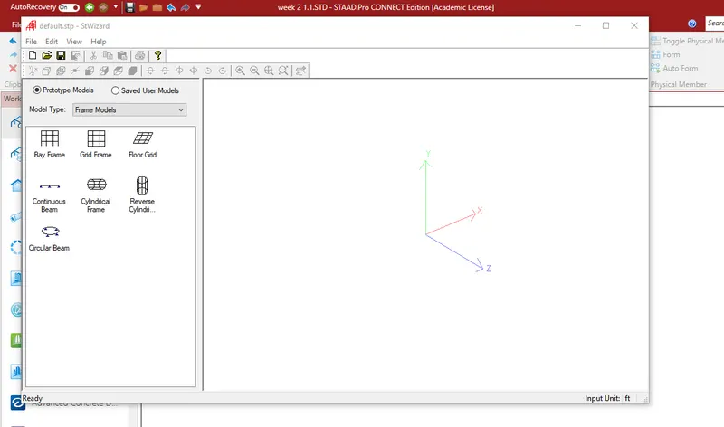
- The parameters to be specified while using Bay frame option are length, breadth, height, number of bays along length, number of bays along width
- To create the parameter of the design by bay frame, click on the structural wizard option under geometry tab
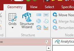
- click frame model and the bay frame
- Enter parameters like length, breadth, height
- Click apply to get the model designed.
4. Name few codal standards incorporated in STAAD Pro software.
There are various codal provisions in STAAD.pro whischa re incorporated as per different country standards, However,the frequently used indian standards are
- For steel, the codal provisions are IS800, IS 800:2007LSD, IS800:2007WSD
- For concrete, the codal provisions are IS456:2016
- For seismic IS 13920 and IS1893:2016
- For wind load - IS 875 part 3.
5. How will you specify the design compressive strength for a RCC section?
- Go to the design option
- Clisck on the define parameter
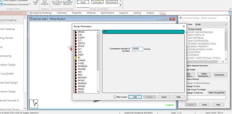
- In the design parameter the FC(compressive strength) of RCC section is to given as the respective value ie., for example, 30000 kN/m2 for M30
2. 1. State the “Input” steps involved in RCC design.
Input steps involved in RCC design
- Geometry - The node locatopns and spacing are done.
- Properties - Sectional propertoes os the section and materail is choosen in this step
- Input/constant/supports - The end supports are psecified to the structure i this section.
- Load and load combinations : Speecified loads and load combinations are done here.
- Design standards : Select the codes andand parameters which you need to design, then select characteristic compressive strength for grade of concrete, yeild strength of rebar, clear cover, main reinforcement dia etc.
- Design command - Then click on commands and select type of design like beam design or column design etc.
- Analysis type - Specify the analysis type.
2. Explain the difference between Fixed and Enforced support condition in STAADPro.
Fixed support :
When the fixed type of support is specified, for those degrees of freedom which are to be treated as fully restrained, staad assumes the displacement to be known quantities whose value is zero. Hence, those degrees of freedom are not considered for the stiffness matrix, and their value is not calculated.
Enforced support :
When the enforced type of support is specified for those degrees of freedom which are to be treated as retrsined, staad assigns a springs for transitional restraints, and rotational stiff springs for rotational restraints. Those degrees of freedom which are free to displace are assigned springs of zerp stiffness. Hence, for all the six degrees of freedom at such supports, the displacements are calculated. The ones which have a stiff spring will end up having a negligible displacement, and those with zero stiffness springs will have a displacement based on the structure geometry, properties and loading.
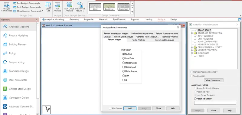
3. 1. Explain the steps involved in analysis of a model using STAAD Pro sequentially.
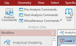
- Select the run analysis tool in the analysis group on the analysis and design ribbon tab
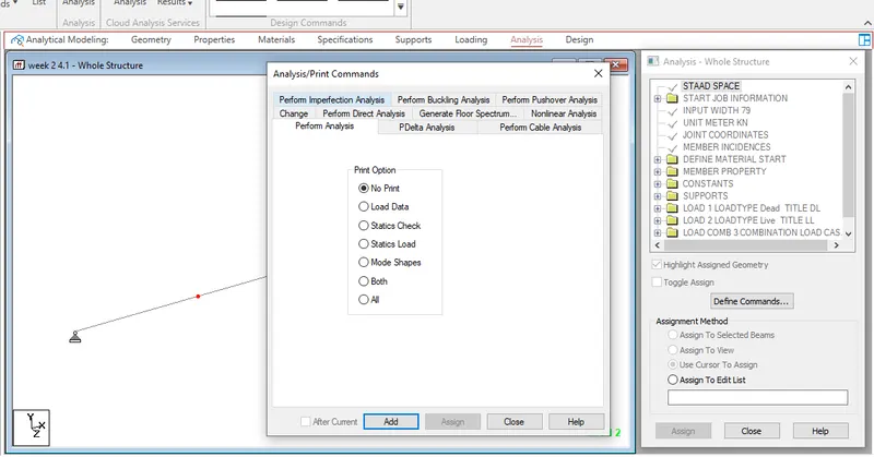
- Click on analysis command
- A window with analysis print commnds pops up
- select the type of analysis which you want to perform
- Click on add
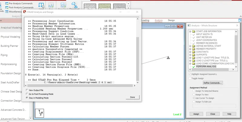
- Click on run analysis, if model has zero errors, output will be generated.
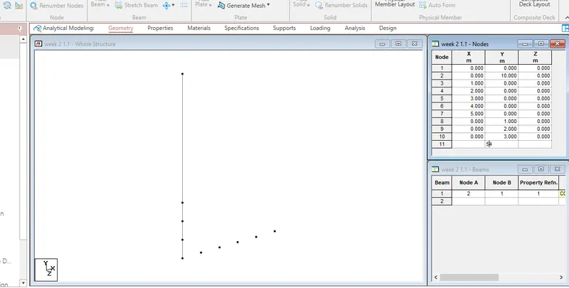
2. Explain the two ways in which a structural framework/model can be created in STAAD Pro software.
The two ways to create the structural framework is
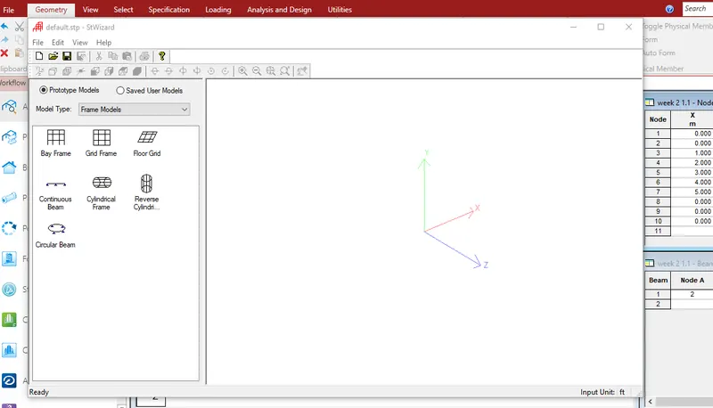
- Creating model by node to node
- Creating model by bay frame using structure wizard option
3. Elaborate the different support conditions in STAAD Pro.
There are three types of support conditions that are predefined in the software
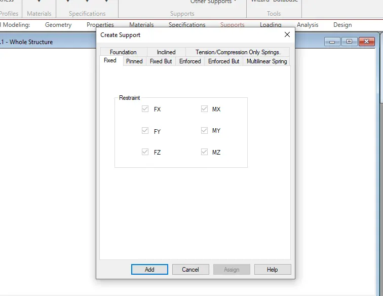
- Fixed - All the transitional and rotational displacements are restrained.
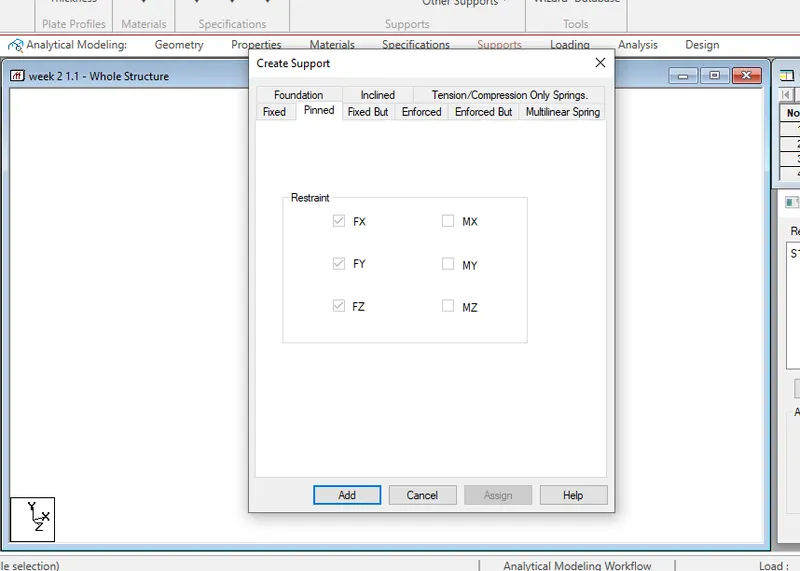
- Pinned - Transitional displacements are restrained but rotational moments are not restrained.
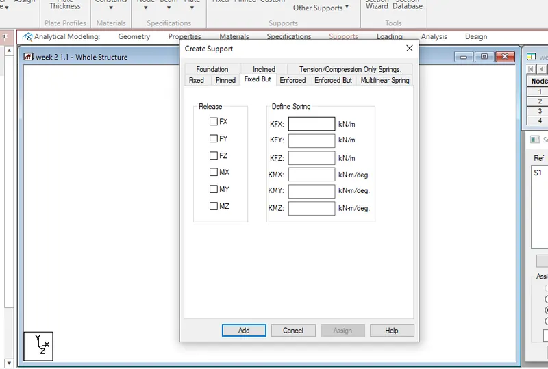
- Fixed but - the fixed butsupport is similar to pinned support as it allows us to provide the degree of freedom to view the displacement either in transition or in rotation.
- Enforced - When enforced supports are assigned to the structure the software allows the springs to itself and the displacement can be calculated however there is no provision to provide the spring constant.
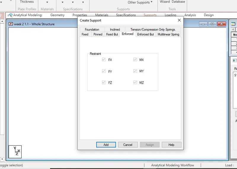
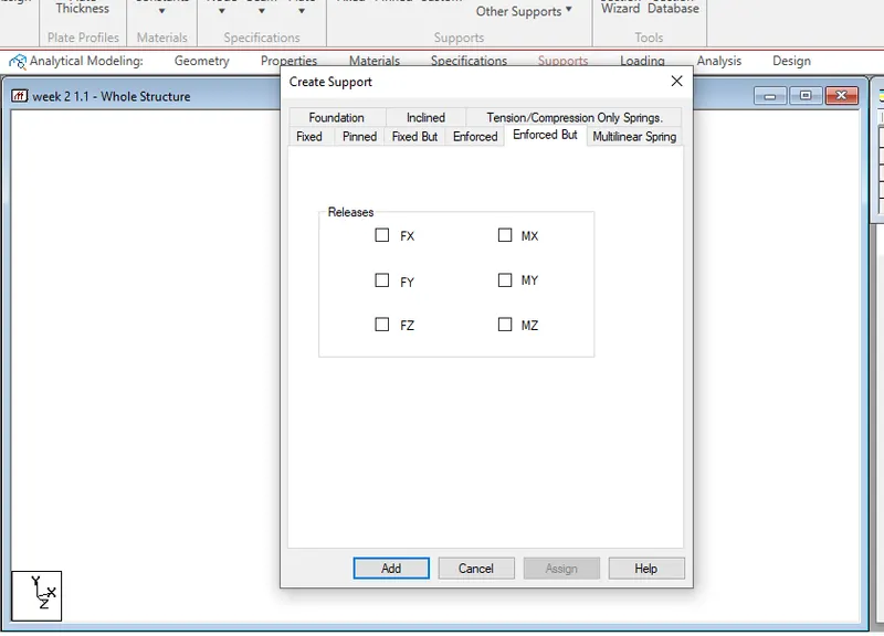
- Enforced but - The software assigns the spring itself with zero stiffness or high stiffness.
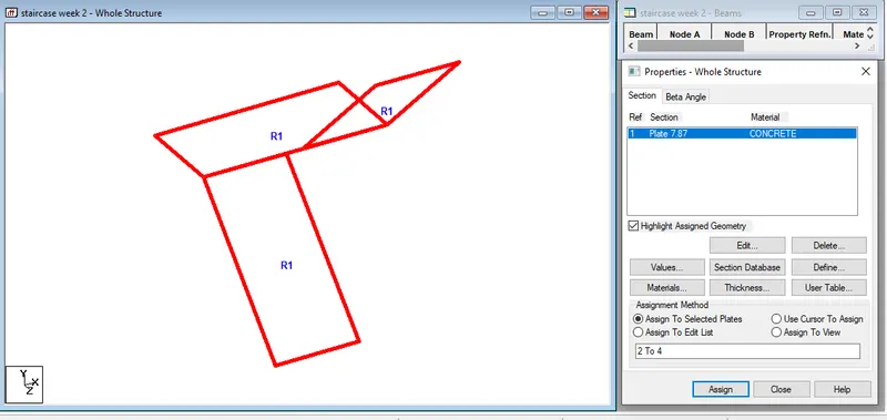
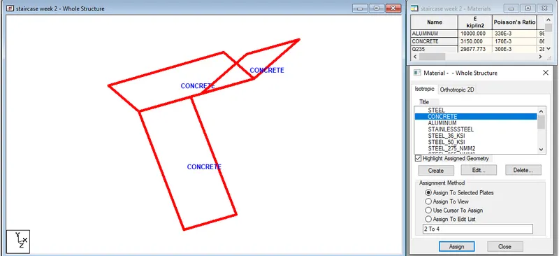
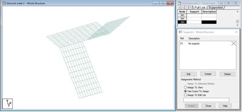
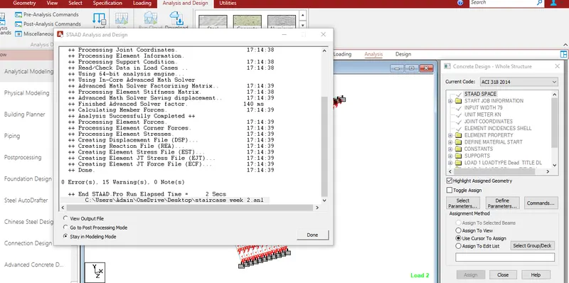
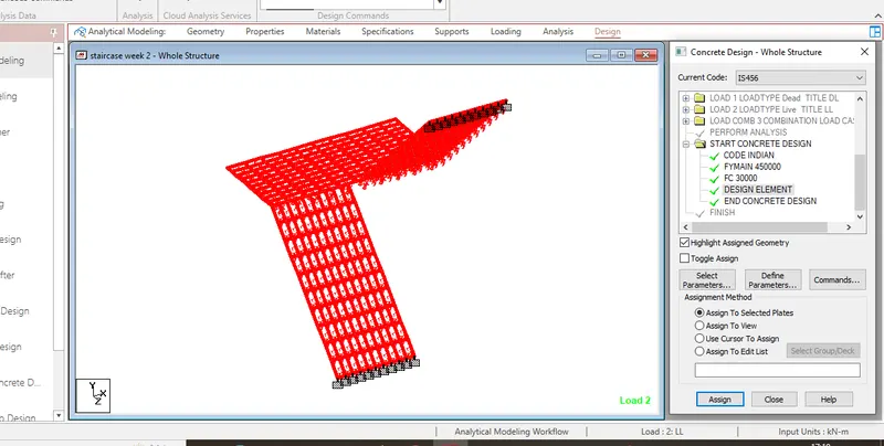
4. How will you extract the stress distribution for a staircase slab?
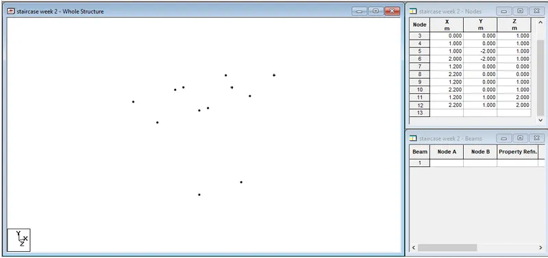
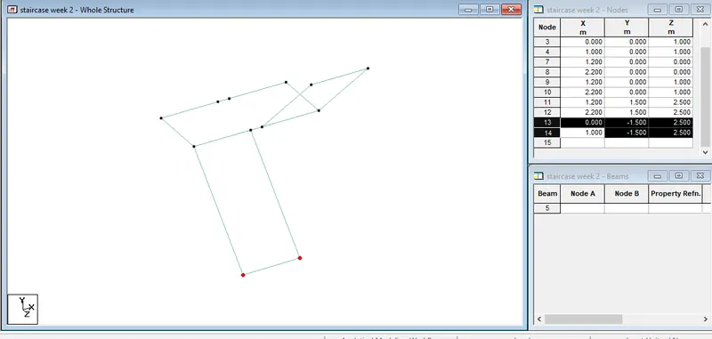
- Firstly define the nodes to thestaircase design
- Then add beams
- Then add support conditions
- Add material properties, add platesolid to represent the staircase slab
- Define and assign loads and load cases
- Click analysis command and add preferred type of analysis
- Run the analysis
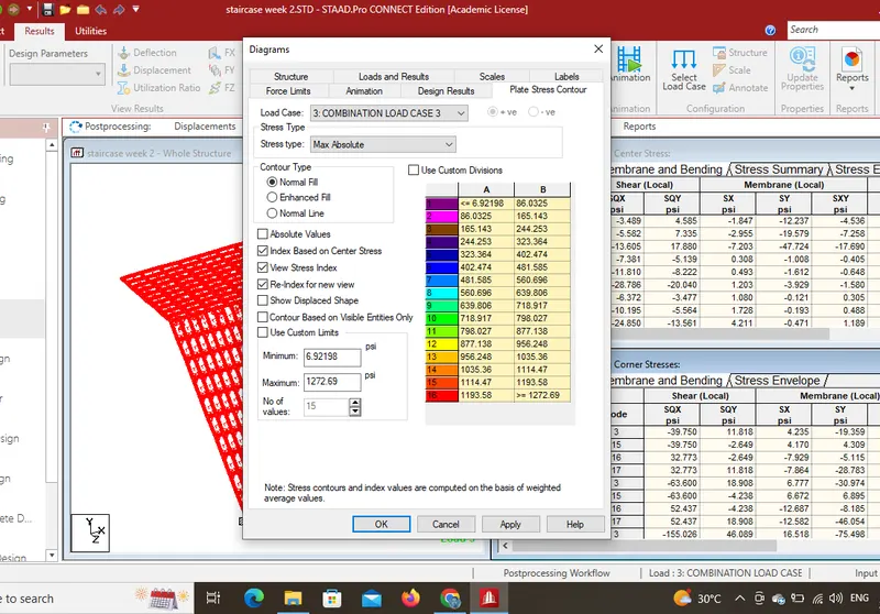
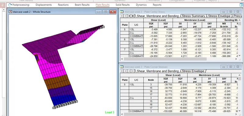
- After the analysis goto the post processing mode ans click plate result, click on plate stress and then one tab will appear, after that click to maximum absolute stress.
- The final result of plate stress is obtained with different color specificatios.
5. Explain the different ways to view SFD & BMD in STAAD Pro.
- After completion of the design the STAAD.pro will automatically provide SFD and BMD
- By entering to the post processing, click ok
- By clicking beam results deflection command
- For deflection, click on the beam deflection
- Click on annotate, select MaxBM to see the value.We can see the SFD and BMD in a graphical view also by clicking on Layout>select graph, SFD and BMD can be viewed graphically.
Practical
1. Analyze the following structural elements and validate the results
A. Simply Supported Beam
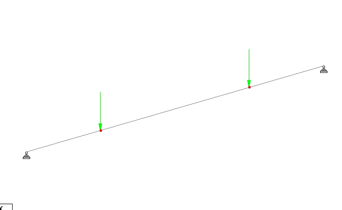
a. A Simply supported beam with two point loads symmetrically placed
b. Span L = 20m
c. Load P = 50kN each
d. Both P located at 5m from each support
Aim :
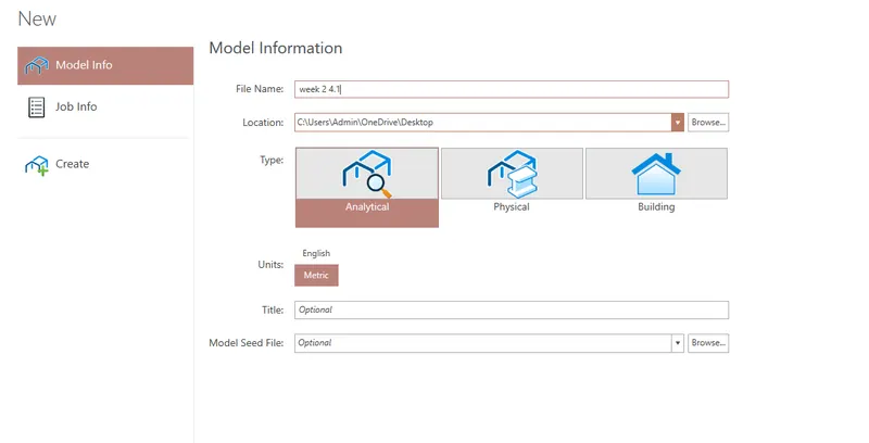
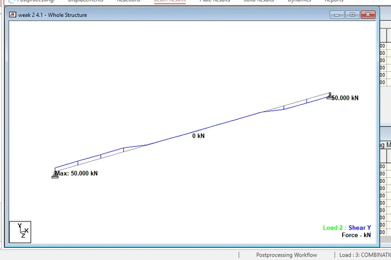
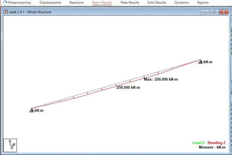
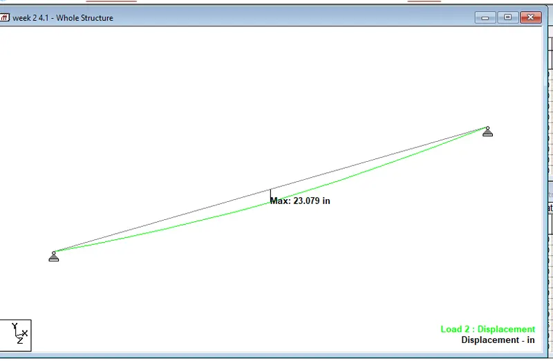
To analyse the simplysupported beam of 20m length having two 50KN point loads in 5m distance from end at both the sides. Also to provide the results as SFD and BMD and displacement
Procedure:
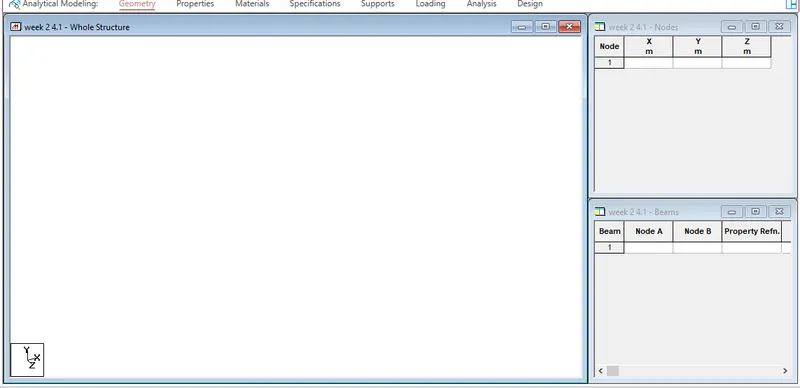
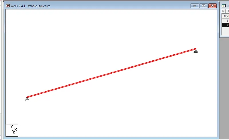
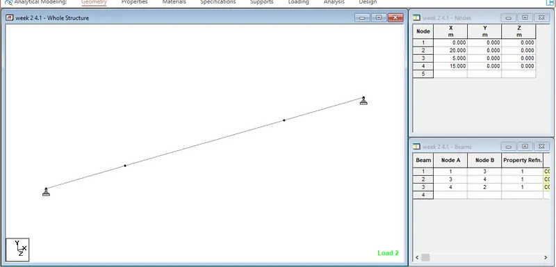
- Open staad pro and create a new template and add nodes using geometry tab
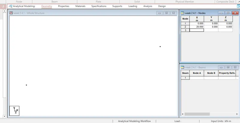
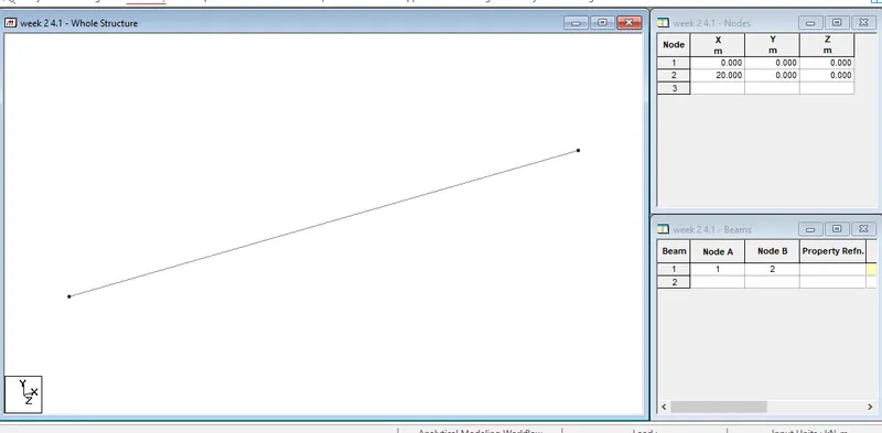
- Add two nodes with the distance of 20m between them and add beam using add beam option
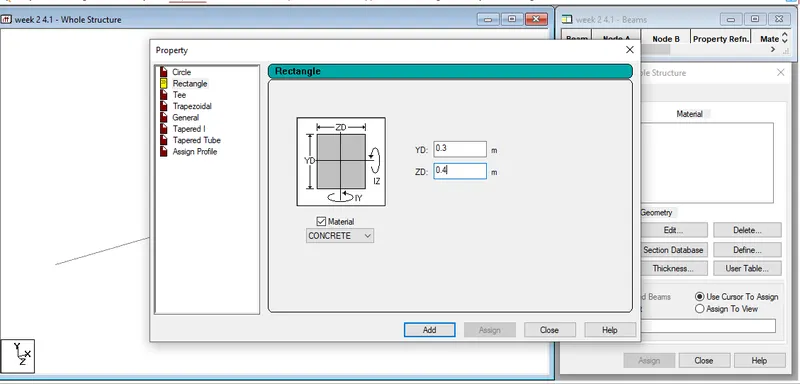
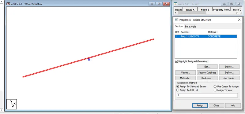
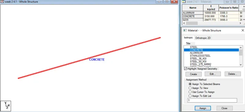
- Go to properties and define beam material as concreteand give dimentions as 300mmX400mm then click add and assign the material to the beam previously created.
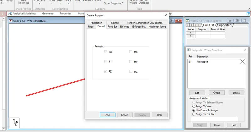
- Now, add pinned supports to both the nodes to make it a simply supported beam and assign them to the given nodes.
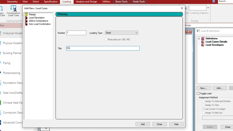
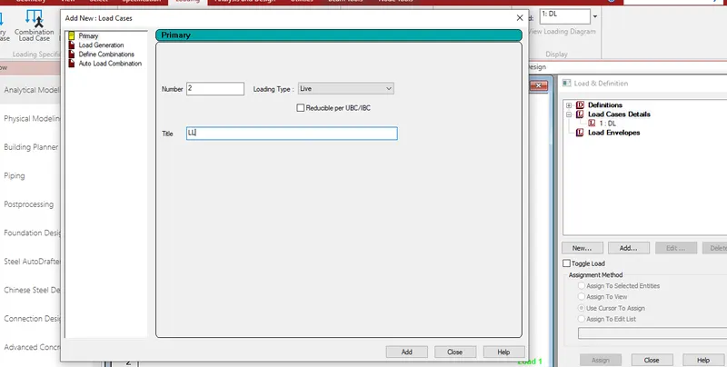
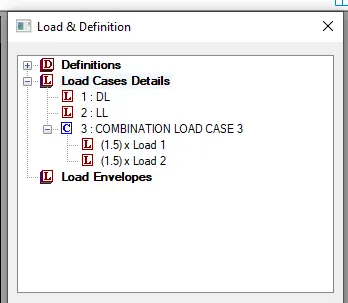
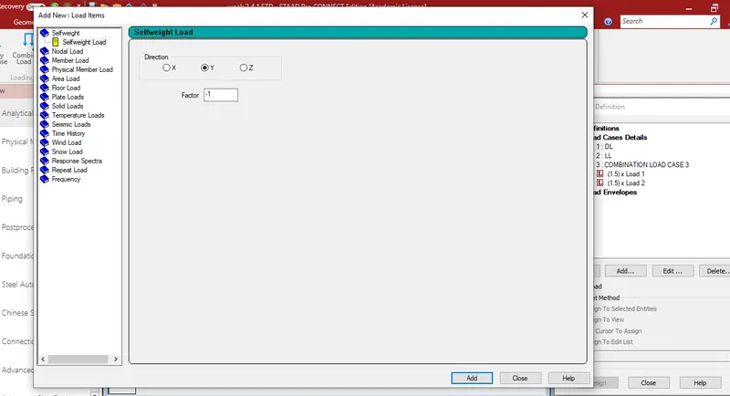
- Now, add dead load, live load and combination load as required
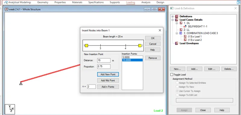
- Add self weight for dead load and two 50KN point loads at 5m apart from both the nodes.
- Assign the loads to the beam
- Finally, analyse the beamusing perform analysis option.
- Check for errors and if there are no errors, go to post processing mode for results
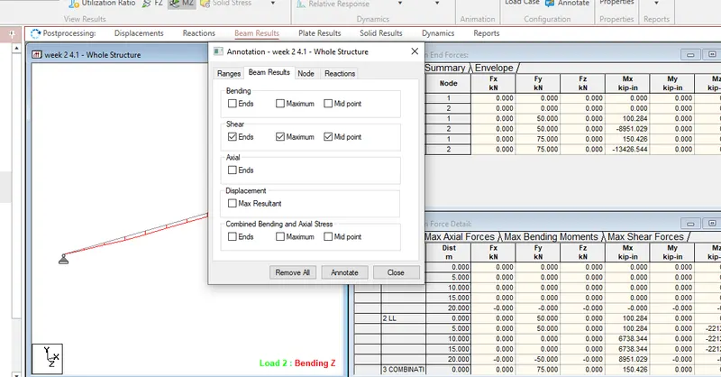
- Then goto beam result tab and select shear force, go to annotate and select values to be displayed
- Select displaceemt, SFD and BMD.
Result :
Shera force diagram
Bending moment diagram
Displacement diagram
B.Fixed Beam
a. Span L = 16m
b. Uniformly Distributed Load w=9kN/m
Aim :
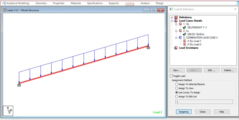
To analyse the fixed beam of 16m length with uniformly distributed load of 9KN/m. Also to provide the results as SFD and BMD and displacement
Procedure:
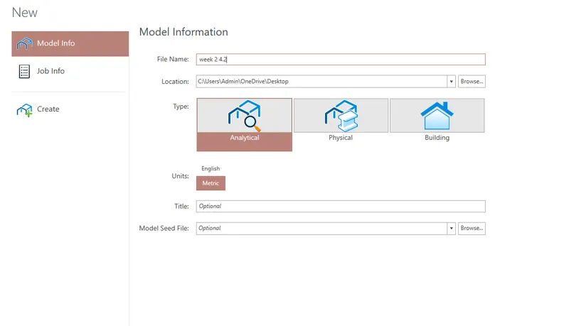
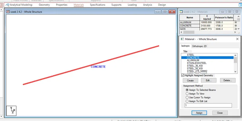
- Open staad pro and create a new template and add nodes using geometry tab
- Add two nodes with the distance of 16m between them and add beam using add beam option
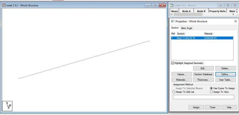
- Go to properties and define beam material as concreteand give dimentions as 300mmX400mm then click add and assign the material to the beam previously created.
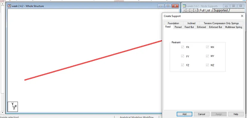
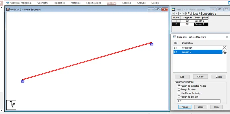
- Now, add fixed supports to both the nodes to make it a fixed beam and assign them to the given nodes.
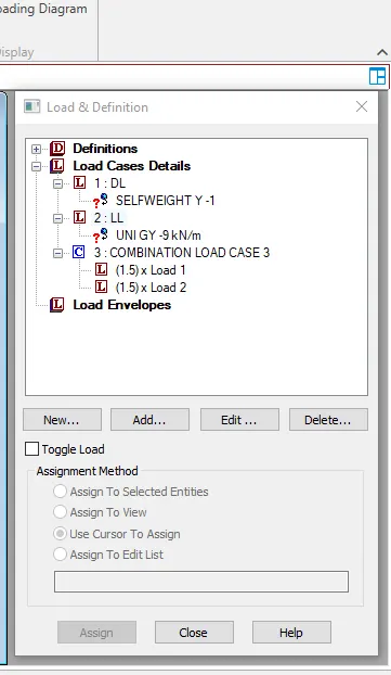
- Now, add dead load, live load and combination load as required
- Add self weight for dead load and uniformly distributed load of 9KN/m as live load
- Assign the loads to the beam
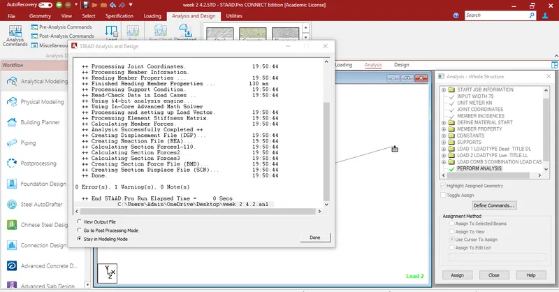
- Finally, analyse the beamusing perform analysis option.
- Check for errors and if there are no errors, go to post processing mode for results
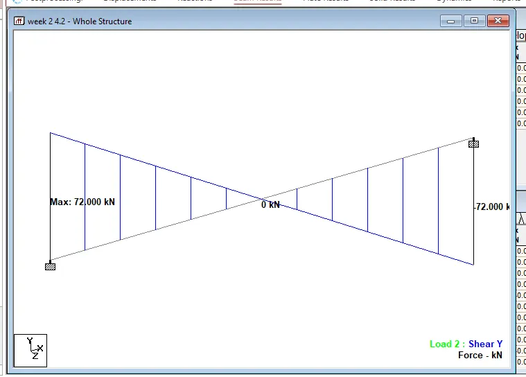
- Then goto beam result tab and select shear force, go to annotate and select values to be displayed
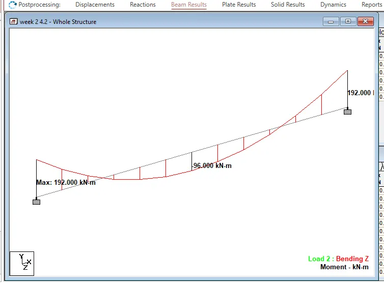
- Select displaceemt, SFD and BMD.
Result :
shear force diagram
Bending moment diagram
Displacement diagram