Week 2 Challenge
WEEK 2 CHALLENGE ON VALVE:
AIM:
For the given model, check for the geometrical errors and perform Topology cleanup accordingly. Set three different target lengths as three different cases and mesh the model.
- Target length = 1mm, 3 mm and 5 mm (i.e. 3 cases)
- Element type = Tria
Apply any one target length from the above at a time for the entire model as One case. Submit 3 different models for 3 cases.
Write a detailed report on your meshing process and also mention which case is giving good results along with the reason.
Given Model:
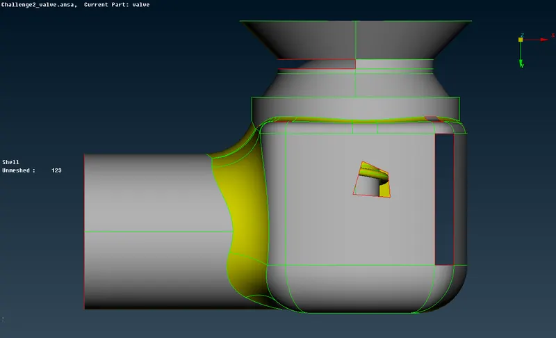
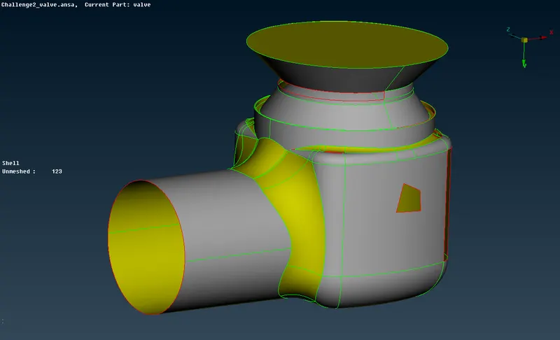
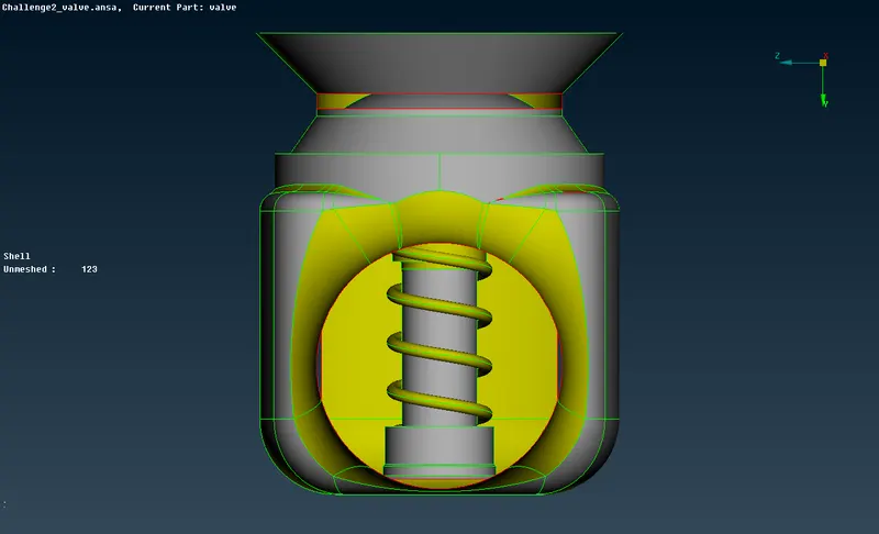
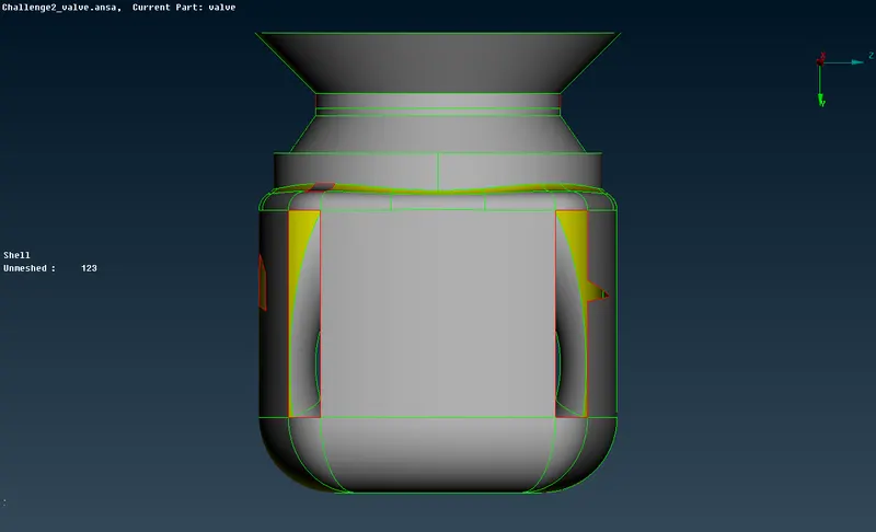
TOPO Cleanup Procedure:
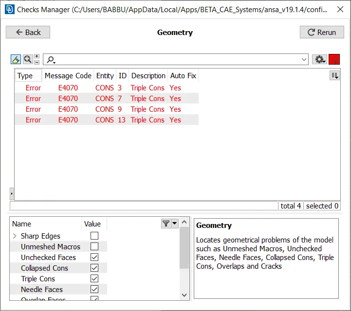
- As we see the model given has many single cons, we want to do some Geometry checks to explore what are the errors we are encountering here,
- SINGLE CONS- the edge which is shared by only one surface.
- DOUBLE CONS- the edge which is shared by two surface.
- TRIPLE CONS- the edge which is shared by three surface.
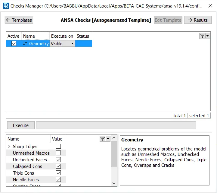
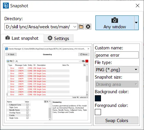
- And the errors are highlighted in red color as shown in the below picture.
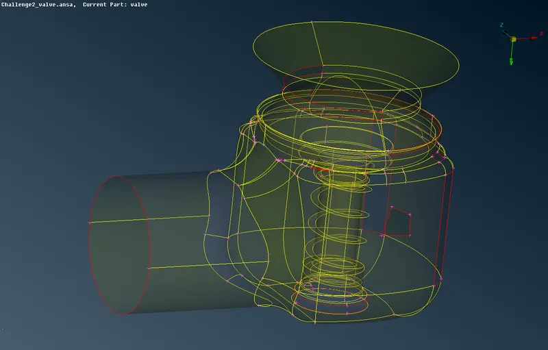
- As we have to remove the errors from the geometry to proceed with the meshing process, we have multiple tools to do so.
- The tools which are used to make the single cons as double cons are,
Method 1:
- Creating new surface
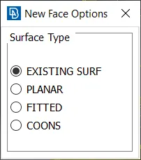
Use loop tool to select multiple cons in a single stroke.
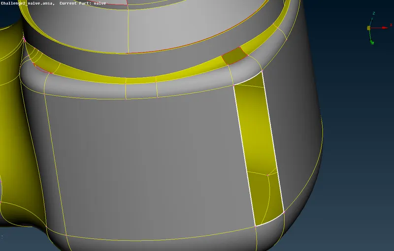
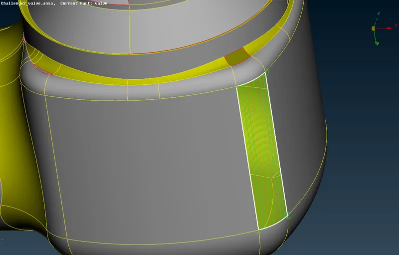
Before using new face tool After using new face tool
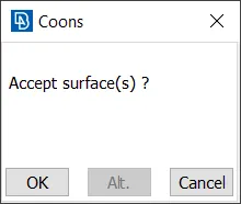
Accept if the preview is ok, which is shown in the above picture.
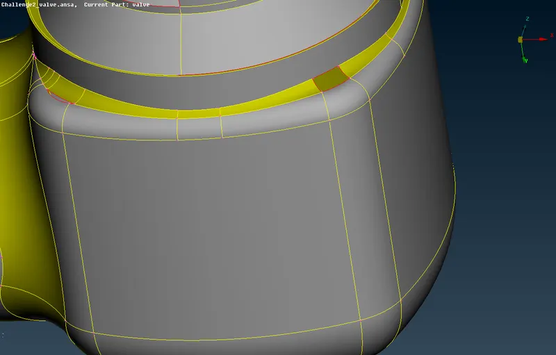
Method 2:
- Fill Hole
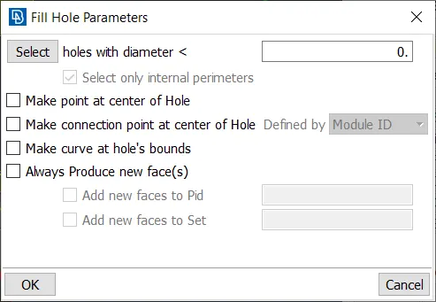
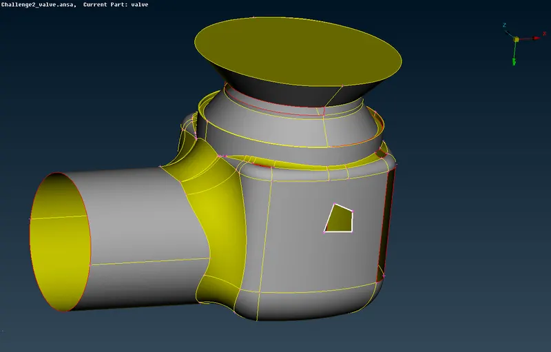
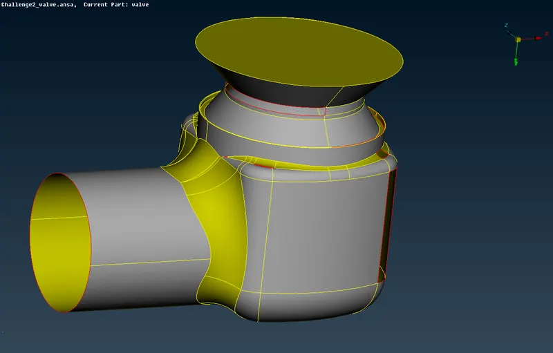
Before using fill hole tool After using fill hole tool
- After completed with every single cons error we have obtained a very nice closed volume geometry which is shown below, now once again check with the geometry checks.
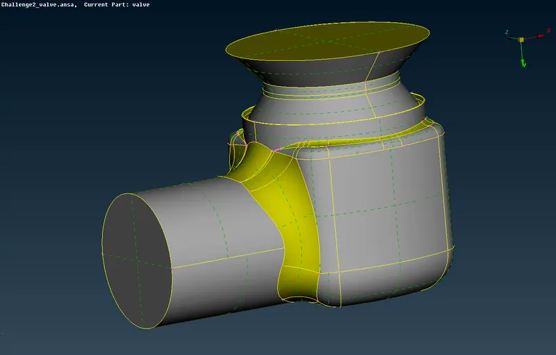
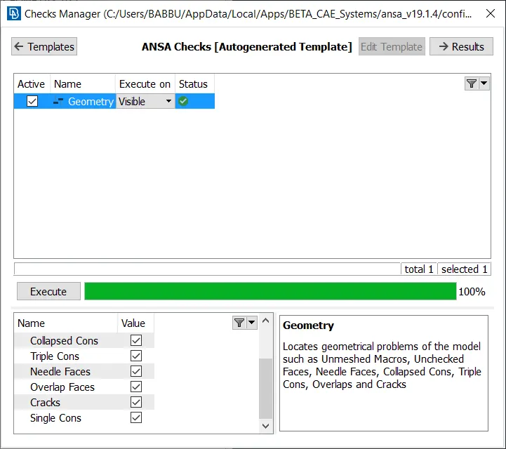
- Since there are no errors, proceed with the next step.
- In the base of the valve we have an opening, as we are doing d=cfd meshing we have to create a closed volumetric mesh.
- So, we have close it as shown in the below picture.
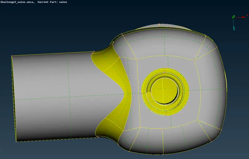
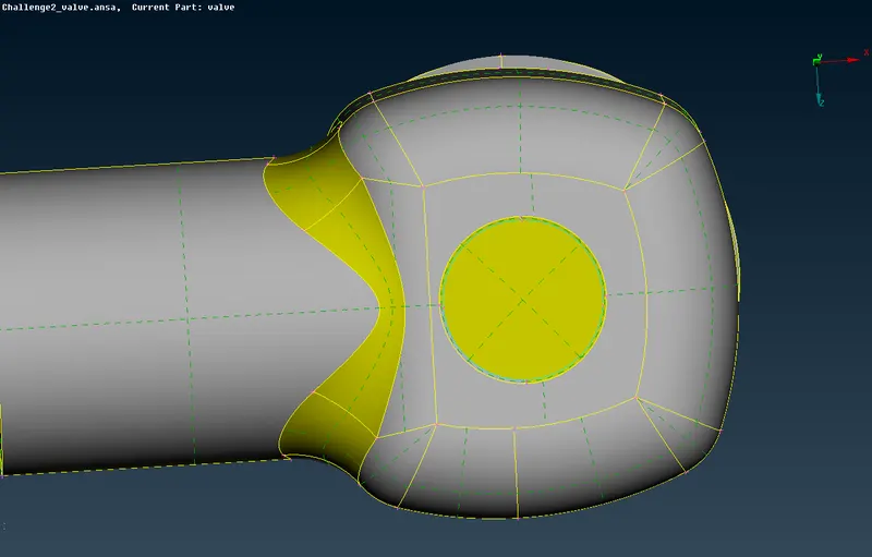
- Now when we are going to perform checks in geometry we are going to face an error named a triple con.
- It's nothing but the base surface which we have closed before is sharing with the three surfaces.
- Chech once the triple cons is necessary or not and keep or remove it accordingly.
- In our case it is necessary so we are keeping it.
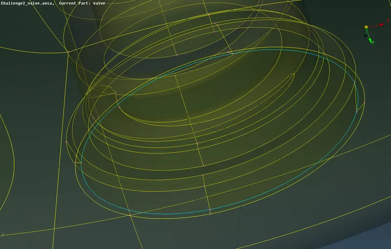
- By this step we are completed with the TOPO cleanup procedures, we can proceed with the meshing process.
Boundary Flagging:
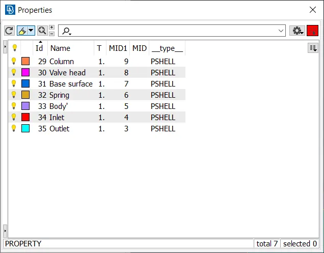
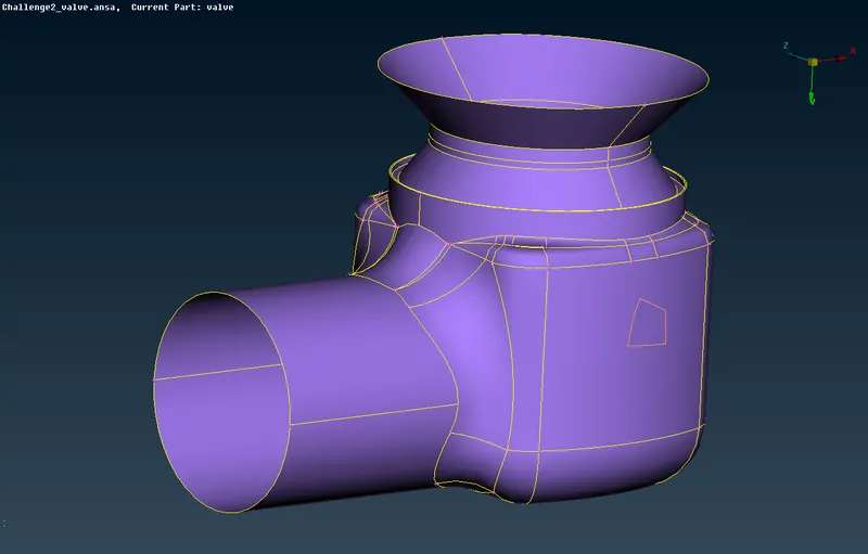
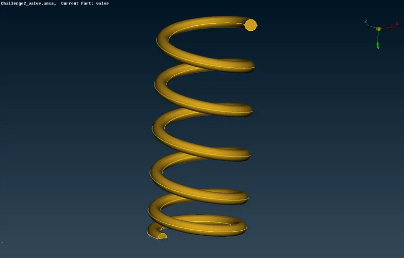
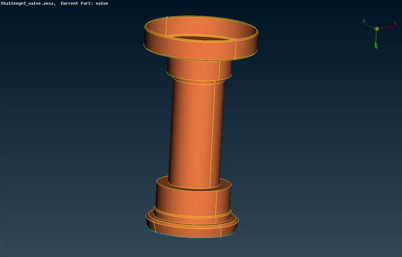
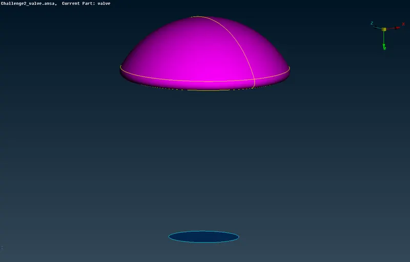
- Before the meshing process, we have to name the PIDs (boundary) individually, as shown in the picture.
- Create a new PSHELL for every single PID.
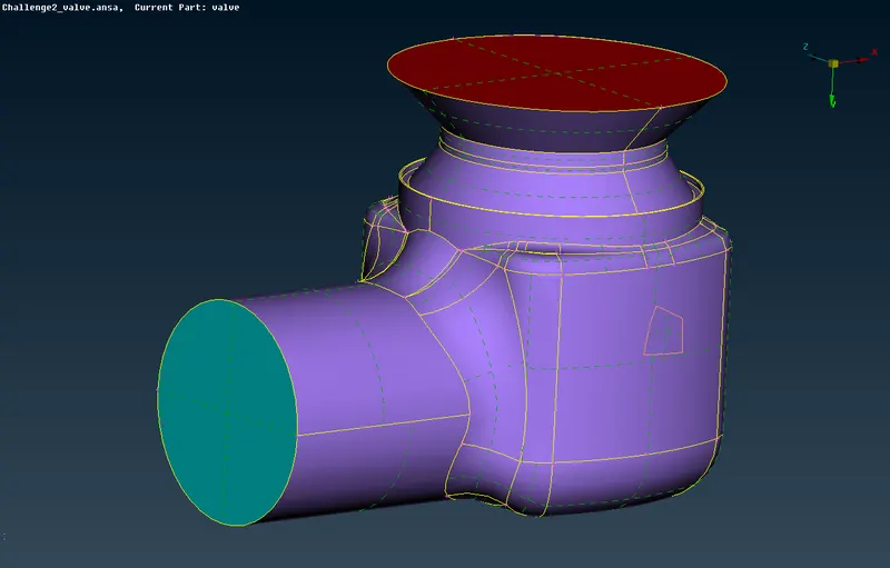
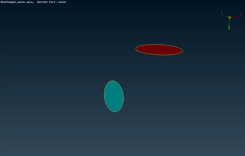
Inlet & Outlet: Body:
Spring: Column:
Valve Head & Base Surface:
MESHING PROCEDURE:
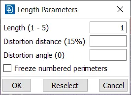
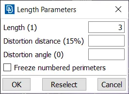
Step 1: Provide the mesh length as given in the challenge in both perimeters and macros for each cases.
- Case1: 1mm
- Case2: 3mm
- Case3: 5mm
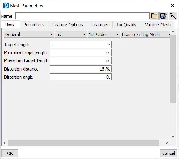
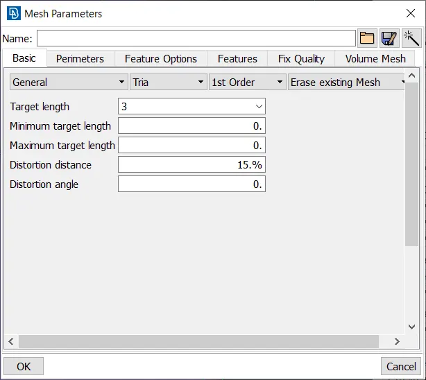
Step 2: Give the mesh parameters such as,
* Mesh Length
* Type of Mesh
* Shape of Mesh - (Tria)
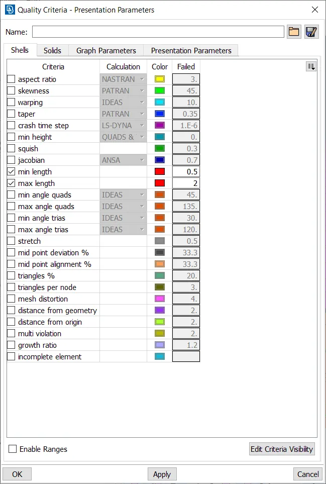
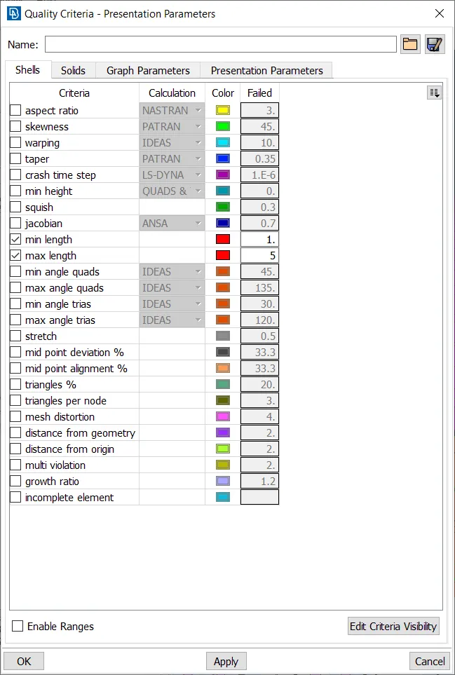
Step 3: Give the Quality of mesh in the Quality criteria tool tab.
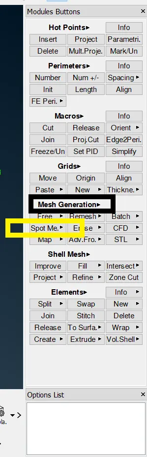
Step 4: After given the required values, to deploy the mesh, use the mesh generation tool. Use spot mesh to generate mesh over the selected faces (PIDs).
CASE 1: (mesh length = 1mm)
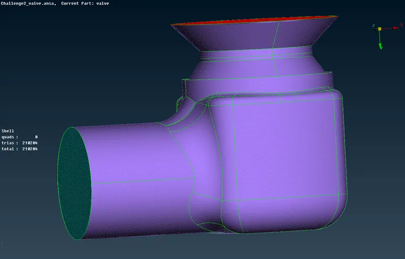
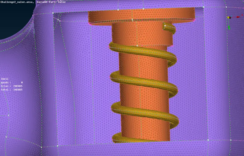
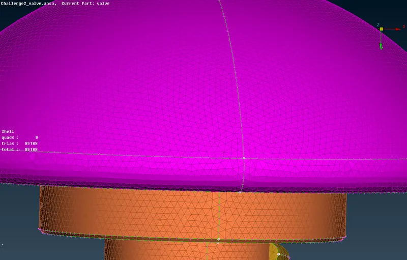
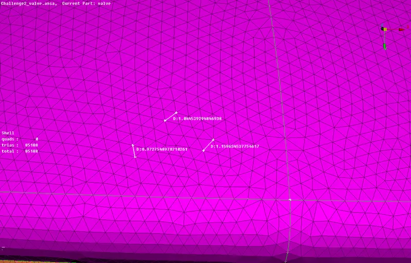
Total number of cells=210204.
- As we can see the mesh length is approximately equal to 1mm for every cell.
- The Geometry has no issues and has not changed in its shape so we can proceed to the next case.
CASE 2: (mesh length = 3 mm)
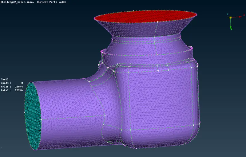
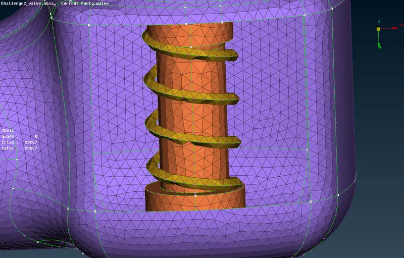
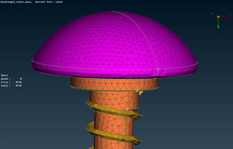
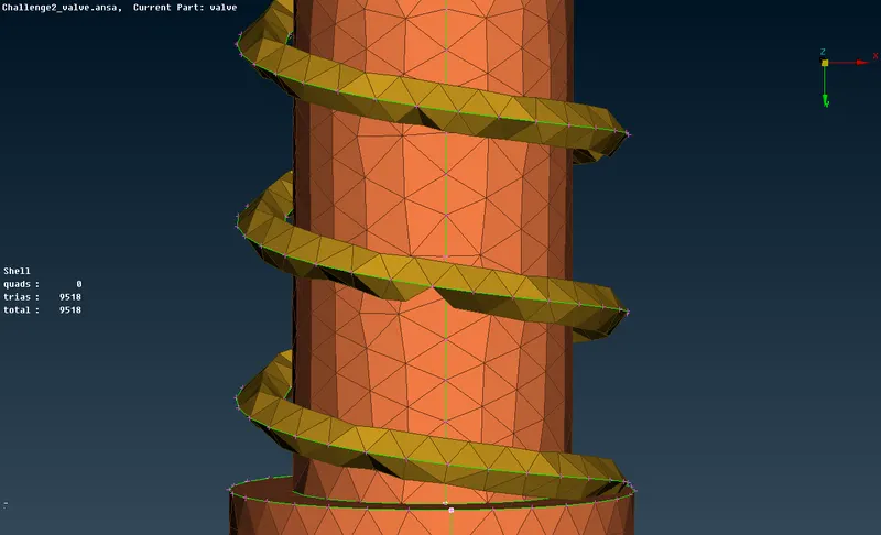
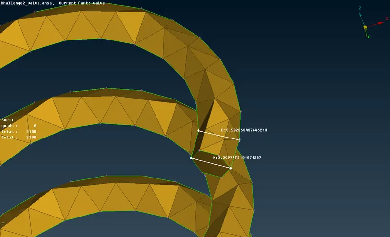
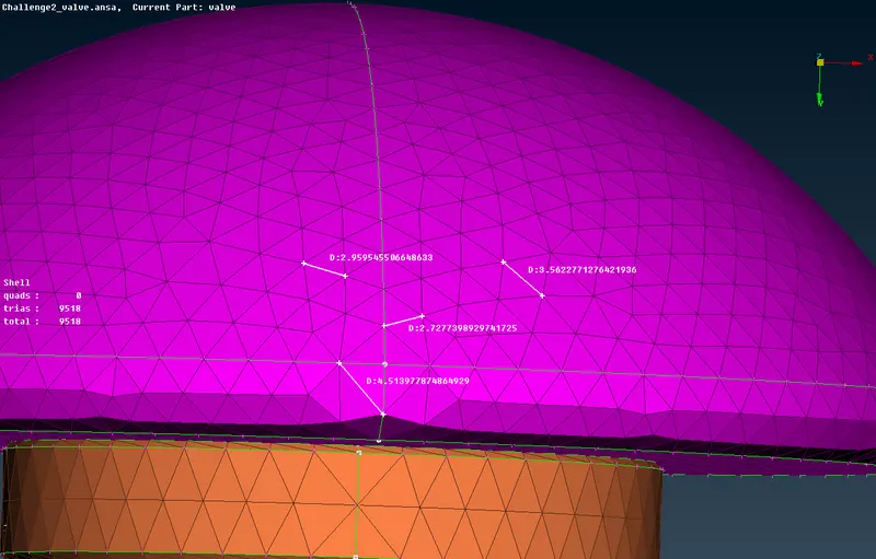
The total number of cells=23944.
- As we can see that the mesh length of cells has been changing in various regions.
- This is because the surface length is small when compared with the given mesh length.
- So we can easily say that this mesh length is not good for CFD simulation.
CASE 3: (mesh length = 5 mm)
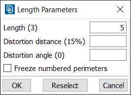
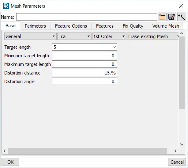
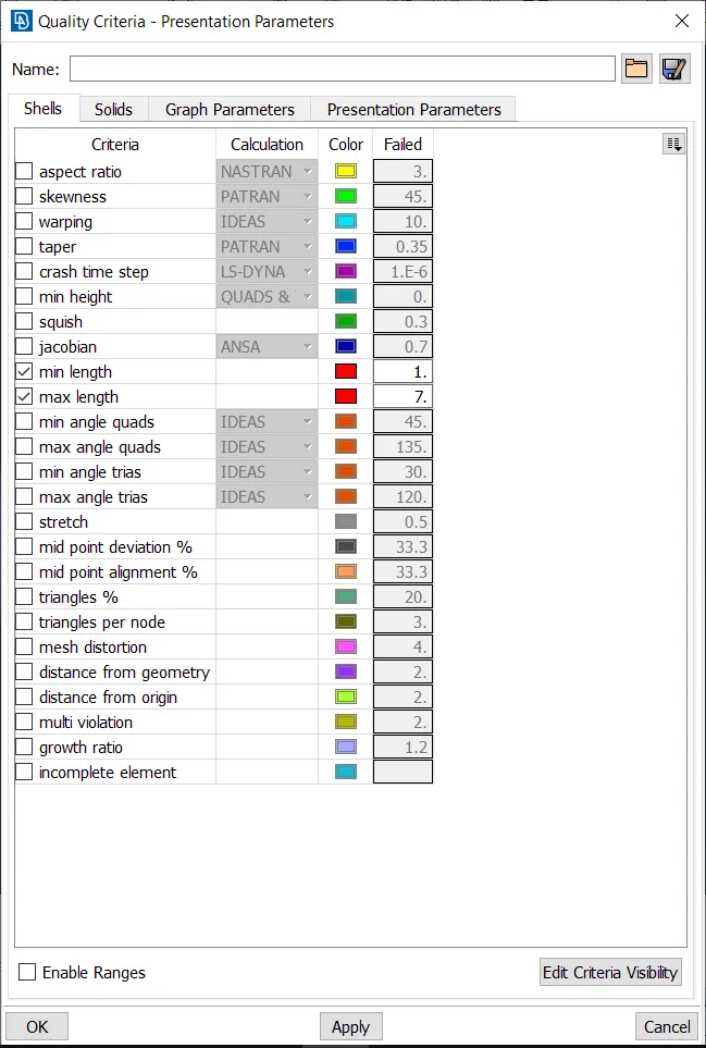
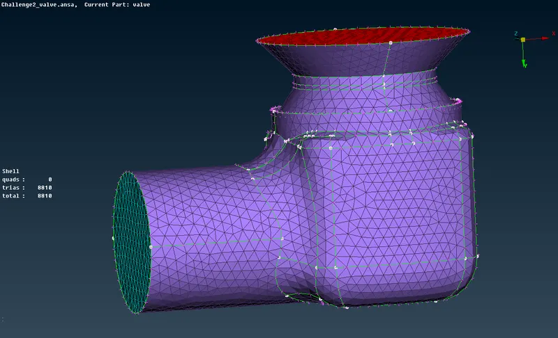
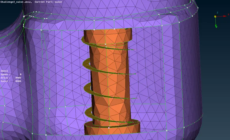
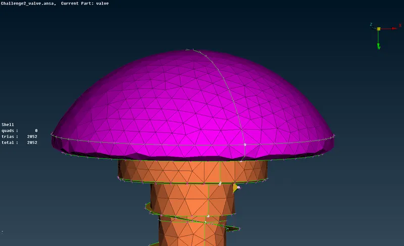
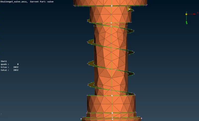
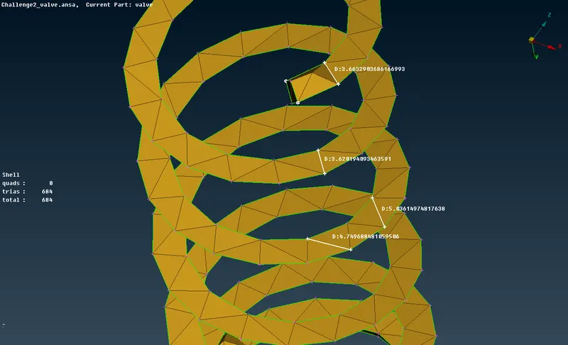
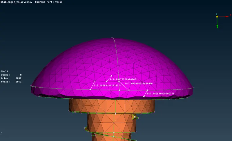
The total number of cells=8810.
- As we can see that the mesh length of cells has been changing in various regions and the geometry has been affected.
- This is because the surface length is very small when compared with the given mesh length.
- So we can easily say that this mesh length is not good for CFD simulation.
Comparison of results:
| Target length (mm) | The total number of mesh elements generated |
| 1 | 210204 |
| 3 | 23944 |
| 5 | 8810 |
Conclusions:
- From the above comparisons, we can see that there is a notable decrease in the number of mesh elements generated with an increase in the target length.
- We know that the accuracy of the solution increases with a higher number of mesh elements (ie, smaller mesh sizes), but a higher number of mesh elements require more computational power and resources.
- Also, when the mesh element size is increased substantially, excessive unshaping of the geometry may take place (especially the smaller components). Hence the results obtained in this case will be useless because of excessive defeaturing.
- Therefore, based on the computational power and resources available, and the geometry specification the mesh size (target length) may be decided. Also, the smaller components of the geometry may be assigned smaller mesh sizes compared to the larger components so as to reduce computational power and not compromising much on the solution accuracy.