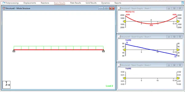
Week 2 Challenge
1.
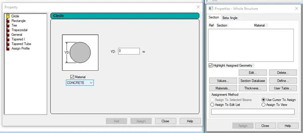
1. Go to properties, choose to define property, circle, and then give the member's radius before assigning the specified circle to the member you just created.
2.
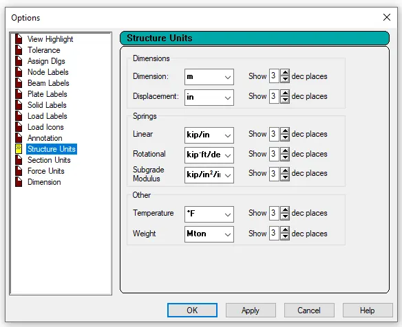
While creating a model go to the unit system and assign the units
Go to geometry in that’s elect input units and assign the units
Go to the view menu in that select display options in that select structure units
3.
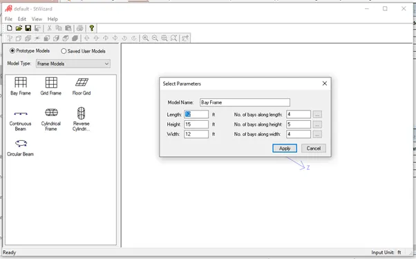
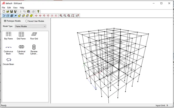
Go to the Geometry tab in the structural wizard, frame model, and bay frame that you've chosen.
Give the specifications, such as length, height, width, and the number of bays along each of the dimensions of length, height, and breadth
4. Euro code, ACI, IS code
5. When designing, choose concrete as the material, then choose the code, describe the parameters, choose FC, and then specify the value.
Q2.
1.
The steps involved in RCC design are
Geometry
Properties
Materials
Specification
Support
Loading and Load combinations
Analysis
Design
2.
STAAD presupposes that the displacements are known quantities with a value of zero for those degrees of freedom that are to be viewed as fully restrained when the fixed type of support is defined. Therefore, the stiffness matrix does not take into account these degrees of freedom, and their value is not computed.
When the enforced kind of support is defined, STAAD assigns a spring with a spring stiffness — translationally stiff springs for translational restraints and rotationally stiff springs for rotational restraints — for those degrees of freedom that are to be considered as constrained. The degrees of freedom that have no restrictions on displacement are given springs with no stiffness. Thus, displacements are computed for all 6 degrees of freedom at such supports. For those with stiff springs, the displacement will be minimal, and for those with zero-stiffness springs, the displacement will depend on the geometry, characteristics, and loading of the structure.
Q3.
1.
Read or study drawings (Plan/Elevation/Section)
Input Geometry
Input Properties
Input Specifications/Constants/Supports
Run analysis
Specify analysis type
Input design standards
Input load and load combinations
Verify results
Design
Represent design as a document and drawing
2.
Node-by-node method
Grid method
Structural wizard method
3.
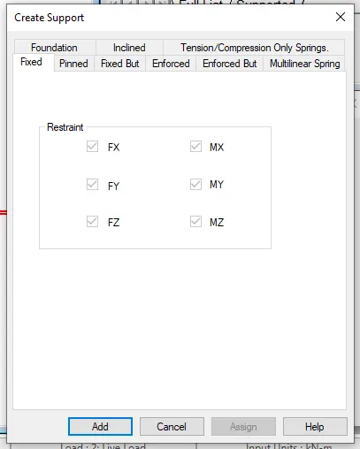
Fixed support
Pinned support
Fixed bug support
Enforced support
Enforced but support
Multilinear spring support
Foundation support
Inclined support
Tension/Compression-Only Springs support
4.
Utilize the nodes in the geometry panel to create the staircase.
Assigning the plate elements to the slab property comes after building the nodes. Next, define the load cases, calculate the area load acting on the staircase, apply the load cases, and combine the load cases with the slab for the staircase. Finally, create a mesh on the plate element.
Run the analysis, then switch to the plate result option in the post-processing mode, where you may pick the stress distribution result and the stress type accordingly. The stress distribution result is then presented.
Stress levels at their maximum and minimum are shifted.
5.
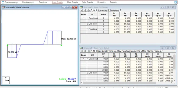
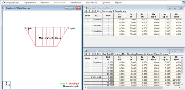
The program will deliver the BMD and SFD when the design is finished and the analysis has been done.
Select Post-processing mode after the analysis, then click OK.
Select "beam outcome" from the deflection command menu.
In response, click the beam deflection button.
Practical
1. Analyze the following structural elements and validate the results
A. Simply Supported Beam
a. A Simply supported beam with two point loads symmetrically placed
b. Span L = 20m
c. Load P = 50kN each
d. Both P located 5m from each support
Ans:
Open the new STADD.Profile
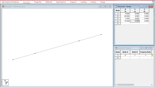
Create the nodes in the geometry tab as per the question
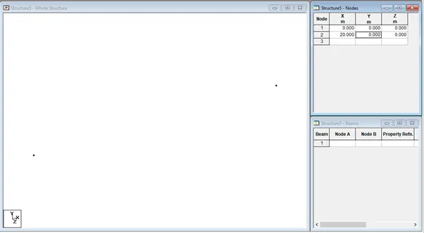
Go to the Geometry tab select add beam and draw the beam by using the beam cursor

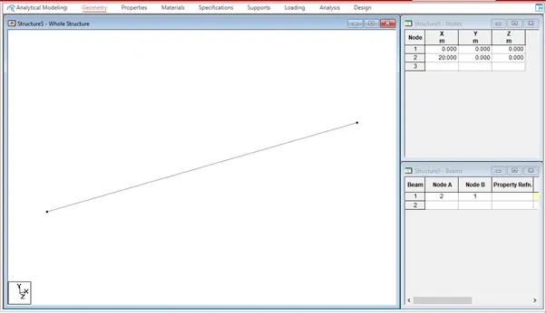
Go to the properties tab and select define and give the rectangular dimensions for the beam
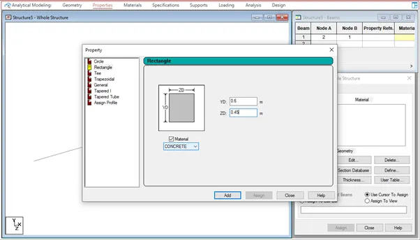
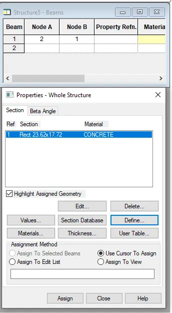
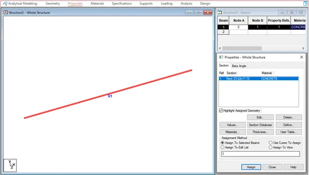
Select the created beam and assign the rectangular property to the beam
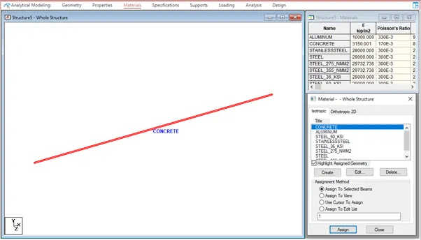
Go to the material tab and give the material concrete
As per the question, load P is located 5m from each support
Go to the Geometry tab and add nodes at 5m and 15m
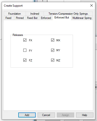
Go to the support tab and create an enforced but support and click on add and add the support to the beam using the node cursor
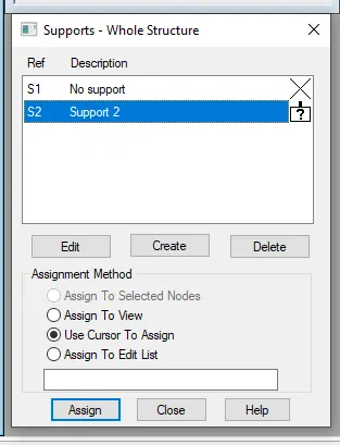
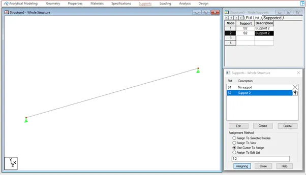
Go to the loading tab and add the load cases
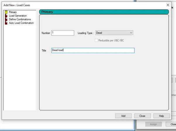
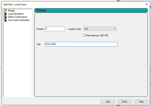
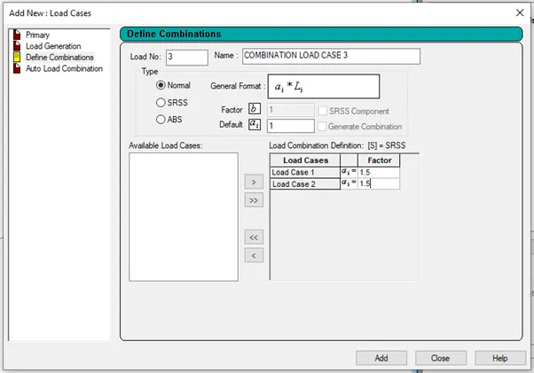
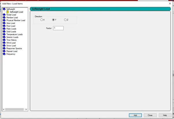
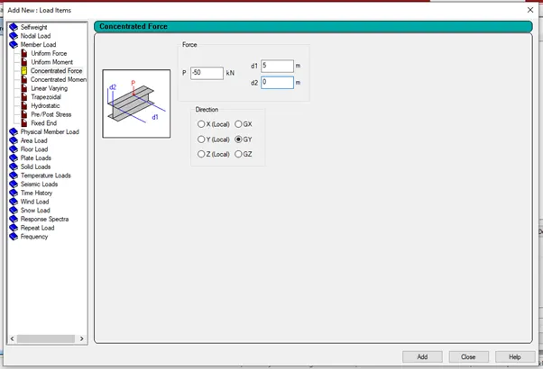
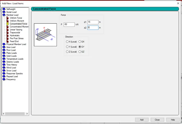
Assign the loads to the beam using use cursor to assign
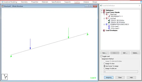
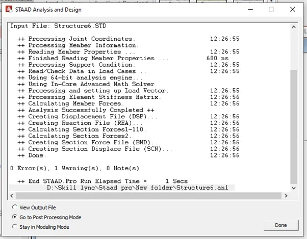
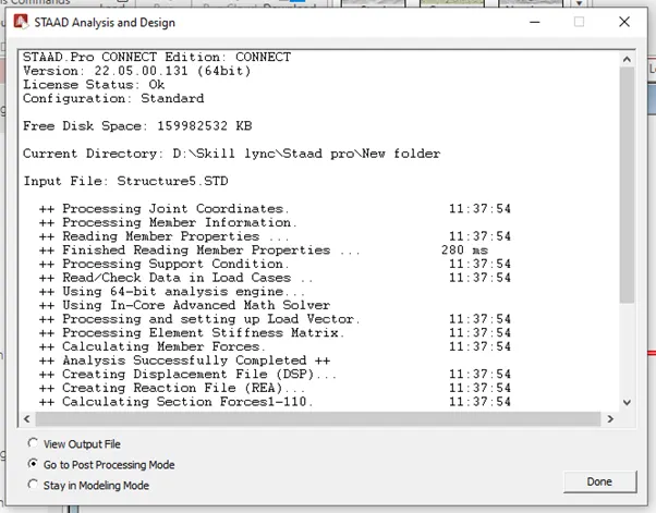
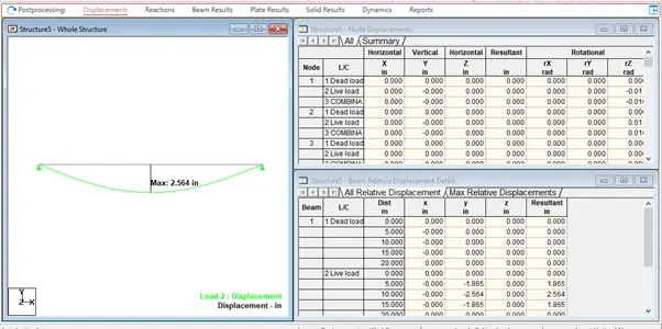
Go to the analysis tab and select the analysis command and do perform the analysis

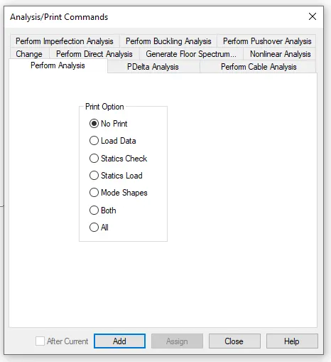
Run the analysis

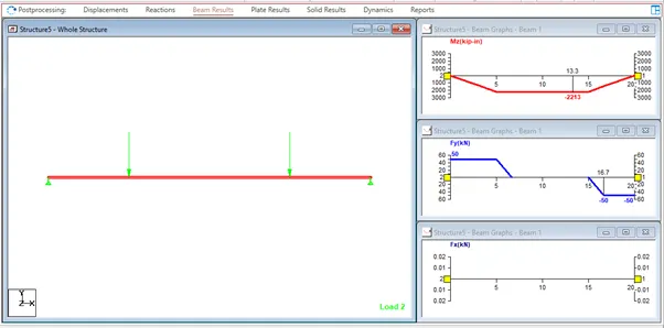
B. Fixed Beam
a. Span L = 16m
b. Uniformly Distributed Load w=9kN/m
ANS :
Open the new STADD.Profile
Create the nodes in the geometry tab as per the question
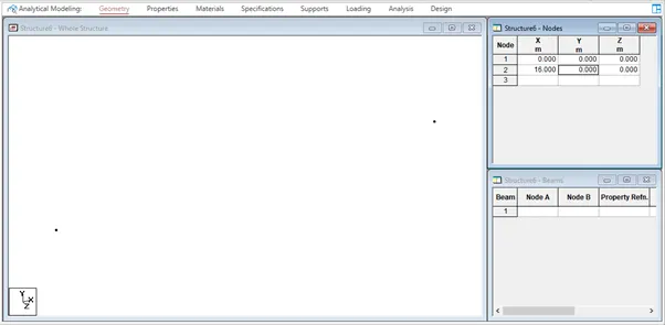
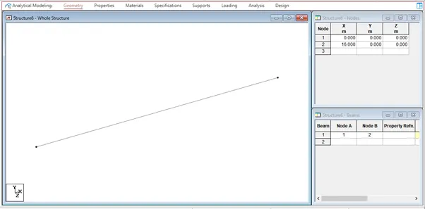
Go to the geometry tab select add beam and draw the beam by using the beam cursor

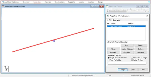
Go to the properties tab and select define and give the rectangular dimensions for the beam
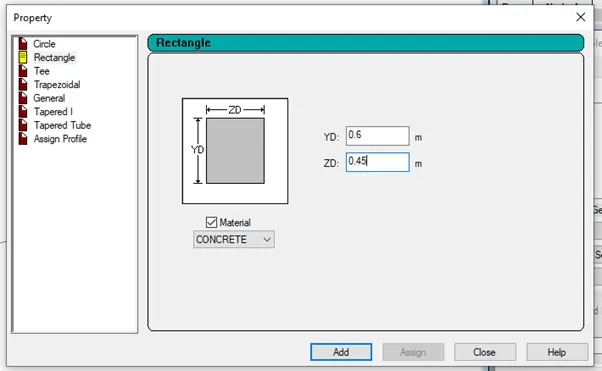
Select the created beam and assign the rectangular property to the beam
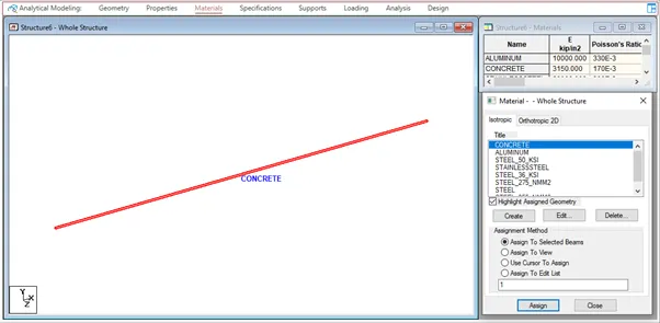
Go to the material tab and give the material concrete
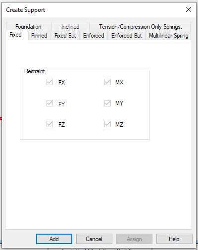
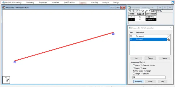
Go to the support tab and create a fixed support and click on add and add the support to the beam using the node cursor
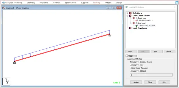
Go to the loading tab and add the load cases
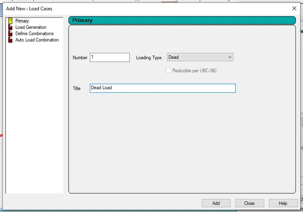
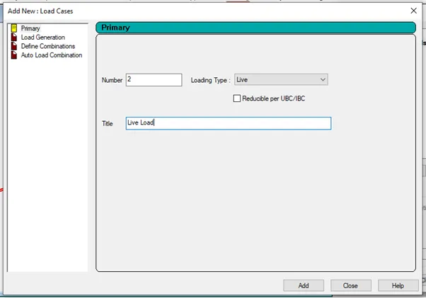
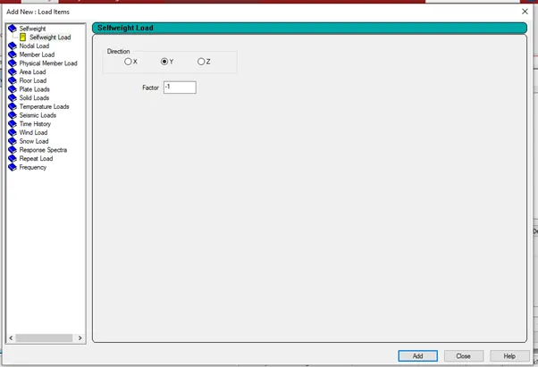
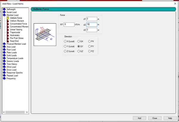
Assign the loads to the beam using Assign to selected beam
Go to the analysis tab and select the analysis command and do perform the analysis

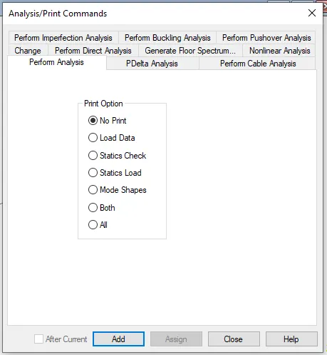
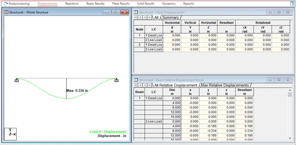
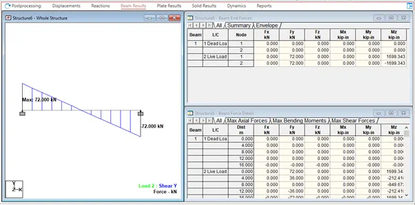
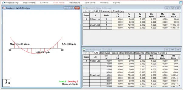
Run the analysis