Week 2 Challenge
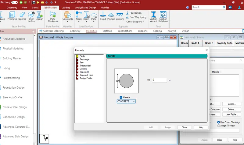
1. 1. How will you assign Circular section to column?
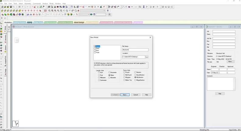
2. How will you assign Unit system to a .std model file?
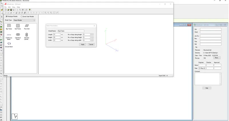
3. What are the parameters to be specified while using “Bay Frame” option?
4. Name few codal standards incorporated in STAAD Pro software.
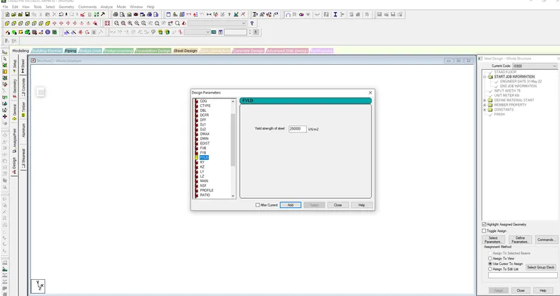
5. How will you specify the design compressive strength for a RCC section?
1. 1. How will you assign Circular section to column?
- Open the STAAD pro sofware ,
- Type project name and select metric >create.
- Create the model in the STAAD pro >Column
- Go to properties> Define parameters,
- Assign circular shape column,
- Radius of the circular column is shown
2. How will you assign Unit system to a .std model file?
- To assign unit system in the STAAD pro
- Go to file menu and then settings
- Open the structural settings
- Change the dimensions as the required,
3. What are the parameters to be specified while using “Bay Frame” option?
- To craete the parameter of the design by bay frame
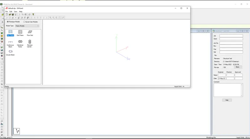
- By clicking on the structural wizard option
- Click on the farme model option
- Click on the bay frame option
- Enter the parameters like length, breadth, height and the bay frame length, breadth and height
4. Name few codal standards incorporated in STAAD Pro software.
- In STAAD pro , the codal standard are in corporated for the steel , concrete, aluminum.
- For the steel codal provision IS 800, IS 800:200, IS800:2000 WSD, IS801
- For concrete the codal provision are the IS456 AND IS13920 For the seismic design.
5. How will you specify the design compressive strength for a RCC section?
- Go to design option
- Cilck on the define parameters
- In the design parameter the fLYD Compressive strength of RCC section is given as 25000 KNm
2. 1. State the “Input” steps involved in RCC design.
2. Explain the difference between Fixed and Enforced support condition in STAADPro.
STEPS INVOLVED IN RCC DESIGN ARE ,
- GEOMETRY : The node location and the node spacing are given
- PROPERTIES : Specify the sectional properties of the section
- MATERIALS: Specify the properties of the material
- SPECIFICATIONS : Specifications are given
- SUPPORT: The end support are given
- LOADING : Need to provide the loading pattern and the loading combination
- ANALYSIS : Need to analysis the model and all the input specifictaions are given
- DESIGN : Finally design are to be done
2. Explain the difference between Fixed and Enforced support condition in STAADPro.
- In STAAD support displacement loads cannot be applied to such models when the fixed type of support is specified
- For the ENFORCED BUT type there is no provision to specify a spring constant.
- The only choices which are built into the program are zero stiffness
3. 1. Explain the steps involved in analysis of a model using STAAD Pro sequentially.
2. Explain the two ways in which a structural framework/model can be created in STAAD Pro software.
3. Elaborate the different support conditions in STAAD Pro.
4. How will you extract the stress distribution for a staircase slab?
5. Explain the different ways to view SFD & BMD in STAAD Pro.
3. 1. Explain the steps involved in analysis of a model using STAAD Pro sequentially.
The steps involved in analysis of the model are
- Before anlysis the model the load pattern and the load combination are to be provided in the model
- Then go to the anlysis option
- Define command
- Select the data for the anlysis of the model by perform analysis P delta analysis , Non linear analysis.
- It depends upon the support condition.
2. Explain the two ways in which a structural framework/model can be created in STAAD Pro software.
The two ways to model the structural frame work,
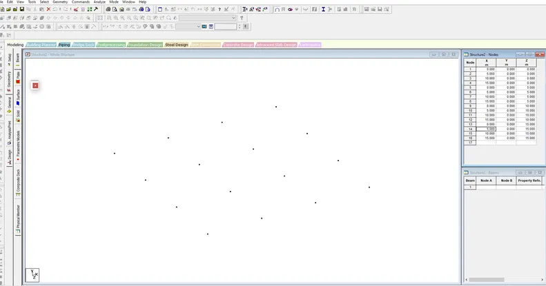
- Creating model by node by node,
- Creating model by Bay Frame work.
-
3. Elaborate the different support conditions in STAAD Pro.
- There are five basic idealized support structure types, categorized by the types of deflection they constrain: roller, pinned, fixed, hanger and simple support.
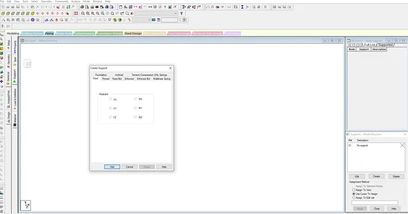
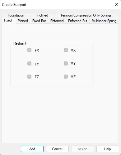
- The Fixed But support condition is used to allow the user to define which degrees of freedom of a node are free and which are fixed. For example, Pinned support is equivalent to Fixed But MX MY MZ (no movement allowed, rotation allowed)
- In STAAD.Pro, linear spring constants are specified as part of "fixed but" support types. Select the nodes that will have the same support condition. On the Specifications ribbon tab, select the Custom tool in the Supports group. The Create Supports dialog opens to the Fixed But tab.
- Roller supports are usually defined to allow translations along certain degrees of freedom(dof). Depending on which dof your support can roll along, you would release that particular dof. For example if your support can roll or translate along global X, you can specify the roller support as FIXED BUT FX
4. How will you extract the stress distribution for a staircase slab?
- Design of stair case slab is done by Node palcement
- The creation of plate is used in stair case
- by use generate mesh
- The stress distribution for the staircase slab is done by viewing colour in the slab of the design.
5. Explain the different ways to view SFD & BMD in STAAD Pro.
- After competion of the design the staad pro will automatically provide the BMD &SFD
- By entering the post processing process , click ok
- By click on the beam results deflection command,
- Reaction click the beam deflection.
Practical
1. Analyze the following structural elements and validate the results
A. Simply Supported Beam
a. A Simply supported beam with two point loads symmetrically placed
b. Span L = 20m
c. Load P = 50kN each
d. Both P located at 5m from each support
B.Fixed Beam
a. Span L = 16m
b. Uniformly Distributed Load w=9kN/m
AIM:
To draw
a. A Simply supported beam with two point loads symmetrically placed
b. Span L = 20m
c. Load P = 50kN each
d. Both P located at 5m from each support
B.Fixed Beam
a. Span L = 16m
b. Uniformly Distributed Load w=9kN/m.
PROCEDURE :
A. Simply Supported Beam
- Open the STAAD pro sofware,
- Define the units >metric and create as shown below
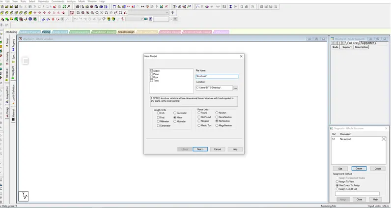
- Add beams as shown below
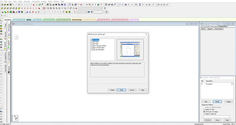
- A graph seen in the window, as shown
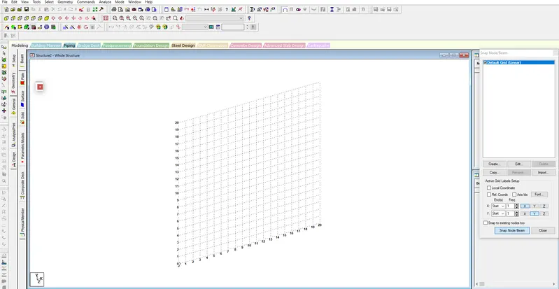
- Then draw 20m length line with node
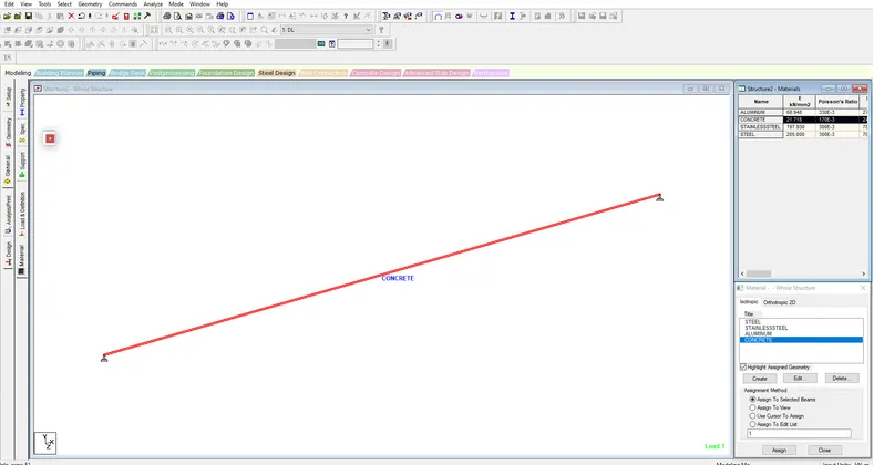
- add the concrete material with 0.23*0.23 thickness as shown,
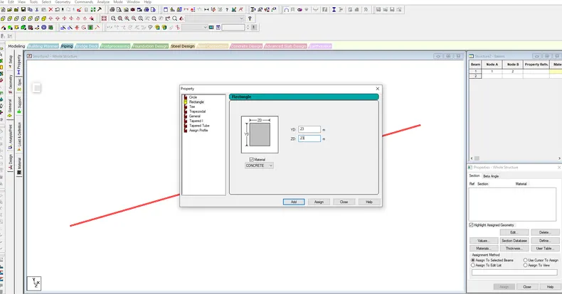
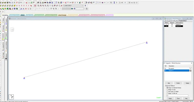
- Then add the supports - simply support each other
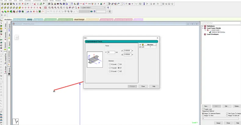
- Then add load P= 50KN
- Both P Located at 5m from each support,
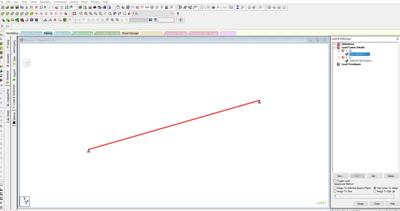
- Then select the load and definition
- add load case details
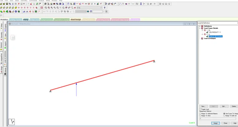
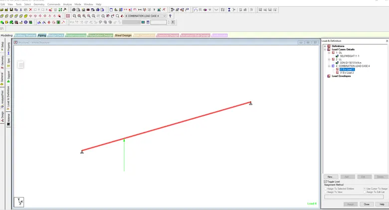
- Then run analysis
- There is noerror in file see attached as shown below
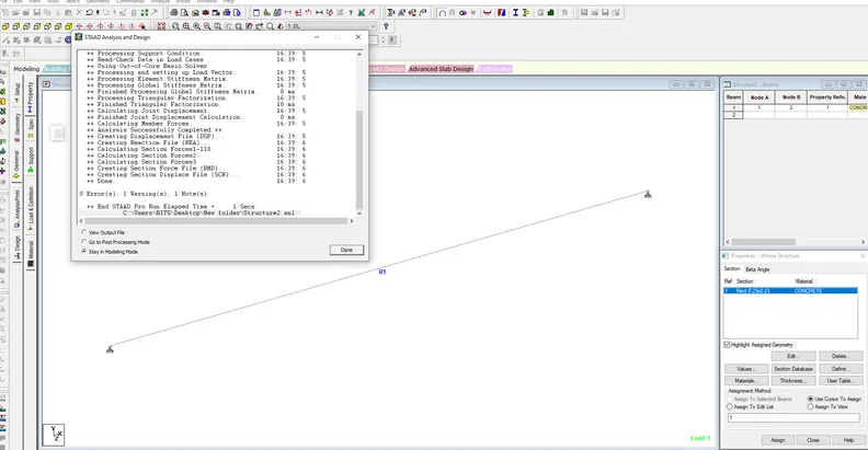
- see the load case displacement
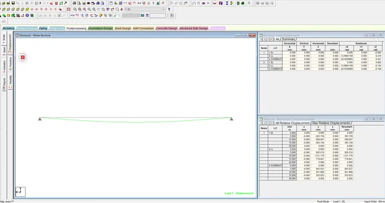
B.Fixed Beam
- Draw the 16m length beam
- Define the support as fixed
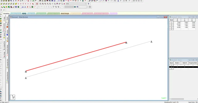
- Then add the concrete material with 0.23*0.23 thickness as shown below
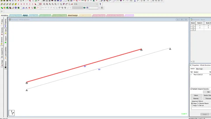
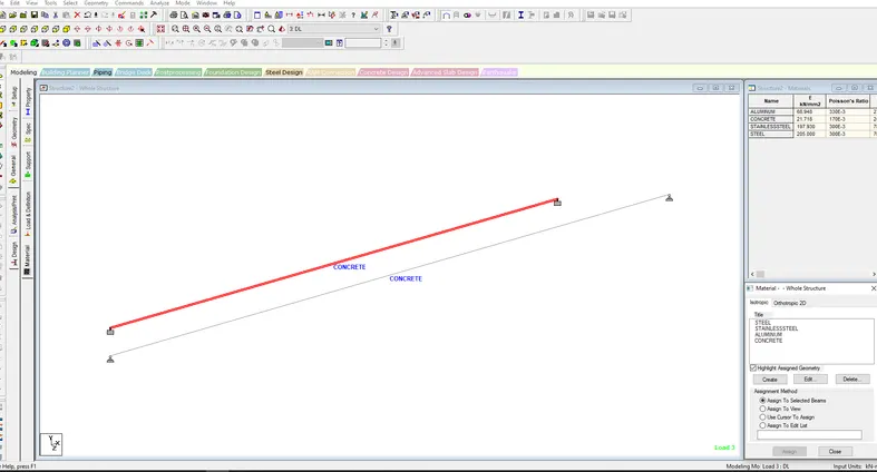
- Then assign loads
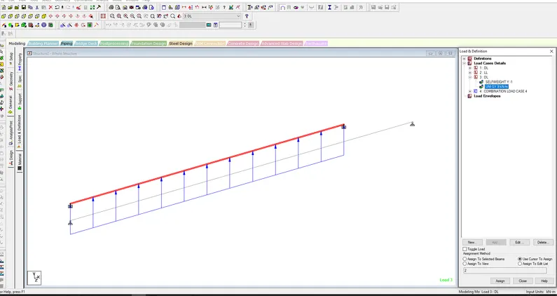
- Then run analysis
- There is noerror in file see attached as shown below
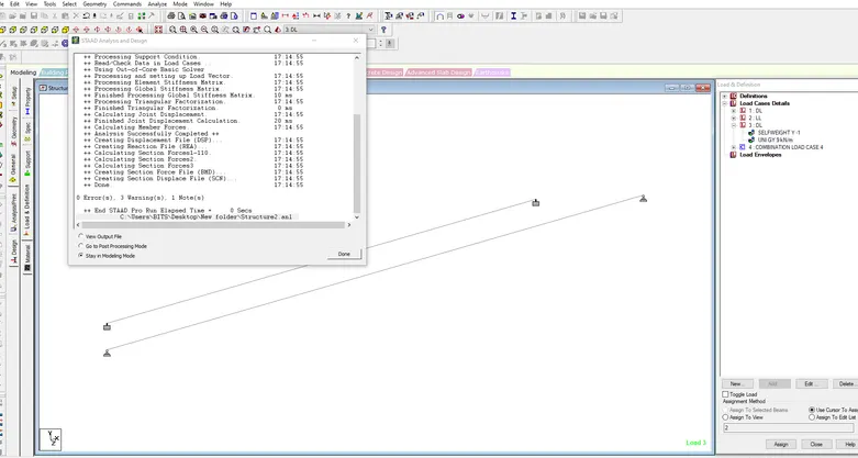
- see the load case displacement
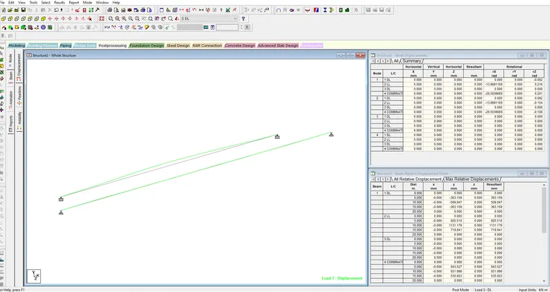
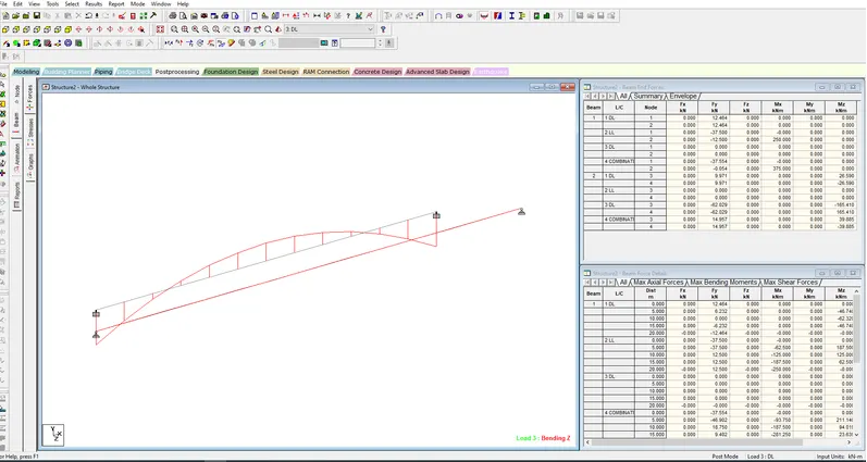
- see the load case 2
- see the reactions
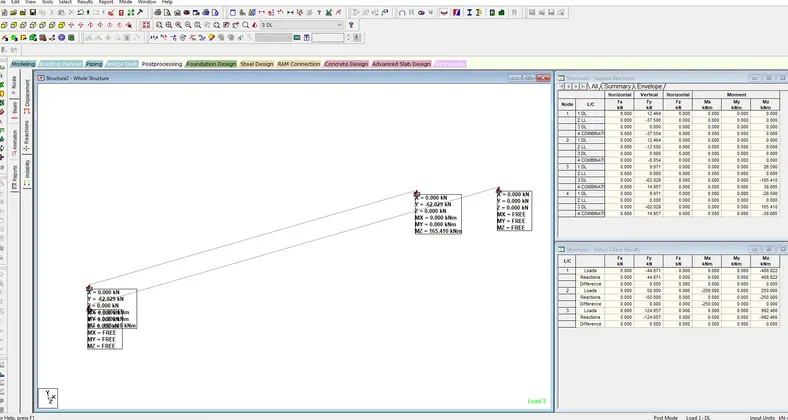
RESULTS :
SIMPLY SUPPORTED BEAMS & FIXED BEAM are drawn and run analysis successfully.