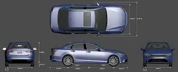
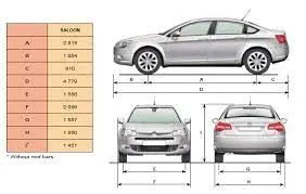
Week 2:- BiW Fixture Basics Challenge
- What is the process of project execution activity?
Project Execution activity:
-
Project execution is the methodology of developing product from the scratch(raw material) to the final stage of achieving desired final product.
Steps involved:
- First step of the project execution activity is to Request For Quotation(RFQ) . Quotation is based on the requirements of the customer in the written documentformat which gives the detailed information about the specifications and time period .
- Discussions will be made based on the concept they are going to adopt for manufacturingthe part and if its satisfy then they will move forward for the offer submission.
- A Letter of Intent (LOI) and purchase order is a short non-binding contract that a binding agreement, such as a share purchase agreement will be made to start working with the requirement.
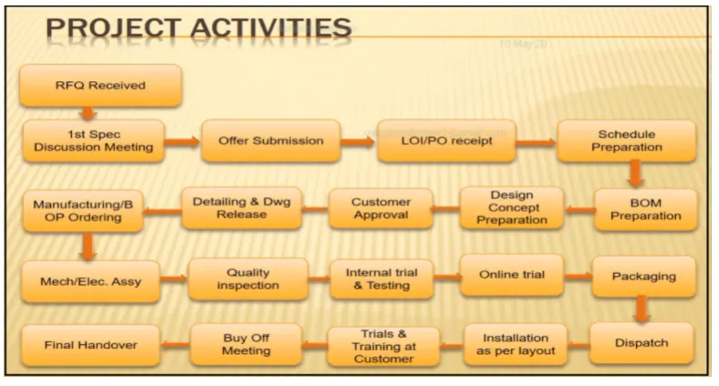
- Then it will move forwardto schedule preparation, list of all activities with their time stamp to get an overall idea whether the product will be delivered in the specified time or not.
- Bill of Materials(BOM) is prepared in a detailed manner to list of all requirements which are made in-houseor outsourcing the specific parts.
- Start with the conceptual model preparation based on the specifications and customer will approve the process that will undergo some modifications.
- Then the detailed drawings are made and the DWG file will be released.
- Then the manufacturing will start based on available parts and all the ordering are done.
- Then the mechanical and the electrical assemblies are taking place at different stations.
- Then it undergo quality inspection to measure its accuracy level using CMM.
- Then it will undergo internal testing process with CAE team and physical testing of components.
- If the products passes all the testing then will go for packaging and it need to be dispatch safely to the customer.
- The customer will start the installation process based on the guidelines or SOP, if required will provide the demo or trials to the customer about the product usage and operations to train him the proper usage.
- Once everything went well , buy off meeting will taking place and handover the product to the customer and periodic maintenance will be taking care for the product based on its maintenance policies.This will be the final procedure for the project execution activity.
2. What are the types of joining processes?
Joining Process :
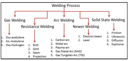
Joining process is used to combine two parts into a single component by providing support in the form the weld or glue or with fasteners. These include different welding operations, gluing, fasteners , soldering brazing, adhesive bonding etc.
Types of Joining process :
1. Mechanical Joining Process
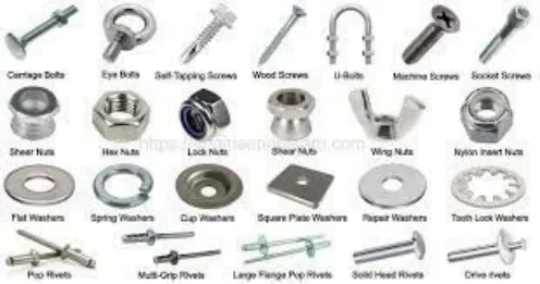
It is the process of joining the different parts with the help of the fasteners like bolts and nuts,screws , rivets.
2. Metallurgical Joining Process
Some of the most important joining methods are
1.Self Piercing Rivets :
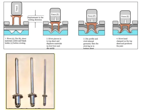
Rivets generally locks itself with the component with the application of pressure. It doesnot require predrilled holes. The advantage of rivet is that it can hold the parts together in the position and doesn't allow the components to move.
2.Hemming and Seaming process :
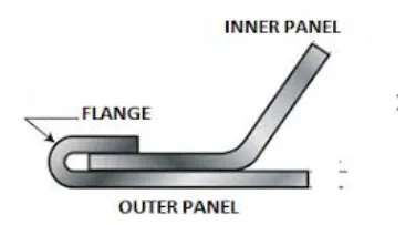
The hemming and seaming are most suited for the sheet metal joining process , in this outer sheet is bended over the inner sheet. Sheet Metal is rolled over the other with different roller size and orientation. Hemming it will just bend the sheet to 180 to form U shaped and there will be 0.2mm thickness gap , where as in seaming that gap of 0.2mm will be filled with the seam material so will glue between the surfaces.
3. Adhesive Bonding :
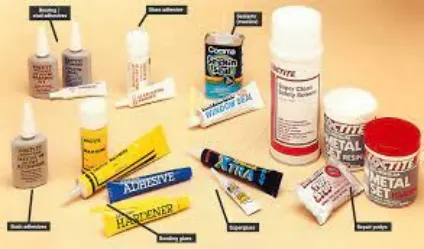
This include glues , epoxy resins, other plastic agents that bond together when we aplly heat and pressure.
4. Soldering:
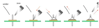
joining process used to join similar or dissimilar metals together by melting solder . Solder is thin metal alloy which is made of tin and lead that is melted using a heating iron. The heating iron is operated in temperatures above 600 degrees fahrenheit which then cools to create a strong electrical bond.
5. Brazing :
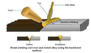
Metal-joining process in which two or more metal componenets are joined together by melting and flowing a filler metal into the joint. Filler material usually having a lower melting point than the adjoining metal. Brazing process not melt the work pieces only the filler materials is melted to join.
3. What is Resistance Welding & its application in the automotive sector?
Resistance Welding :
The resistance welding or spot welding is generally used welding technique that is most suited for the BiW components. In this process the metals can be joined together by application of pressure and conducting a strong electric current through the metal combination to heat up the welding joint and melt the metals, forging them together.
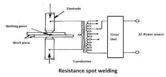
Then these two electrodes exert the pressure on the metal surface against each other and uses current to produce heat and join the adjoining metals. After that we apply pressure over certain period of time to make sure the weld is properly done and it also provides good bonding with the surface.
1. Resistance spot welding :
Spot welding process is used primarily for welding two or more metal sheets together by applying pressure and heat from an electric current to the weld area. Electrical resistance spot welds are formed by bringing electrodes in contact with sheet metal. Electrical current flows though the electrodes and encounters high resistance at the interface surface, between the sheets. This resistance creates a large amount of heat, which locally melts the sheet material.The diameter ranges from 100 to 800 μm depending on the beam diameter, the material, and the laser power. The spot welding process can be divided into four phases: heating, melting, melt flow dynamics, and cooling. Depending on the intensity, evaporation of material may occur.
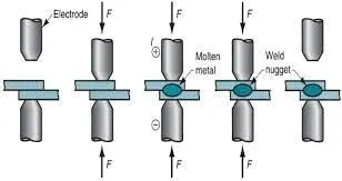
The electrodes used in the process are commonly made of copper-chromium alloy and zirconium alloy.
Applications:
They are commonly used in automotive sectors of the chassis, BiW components include welding of different components together to form the vehicle structure.
Advantages :
- Short weld time and high welding strength
- Easily adaptable to robotic techniques
- High durability.
2.Resistance Projection Welding :
The projection welding process depends on heat generated by an electric current to join metal pieces together. Projection electrodes are capable to carrying high current so will used to weld thicker materials.
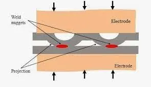
Projection welding is difference with the spot welding is by the shape of the electrode. The shape of the projection electrode does not have specified standard because the shape entirely depends upon the metal that needs to be welded upon. The tip of the electrode will have embosses that are specially made to be projected exactly along the shape of the metal to be welded upon.
Applications:
Special nuts, small fasteners, special bolts, studs
Advantages :
- Less amount of current supply to perform welding.
- No thickness limitations.
- more suitable for automation process
Disadvantage :
- Cost of the welding is competitively higher.
- Projections cannot be made on thin workpieces.
- Not suitable for the brasses and copper materials.
3. Resistance seam welding :
Resistance Spot Welding process is which used to make continous welding throughout the surface face geometries of the welding electrodes themselves to focus the welding current at the desired weld location, and also the application of force to the workpieces. Once sufficient resistance is generated, the materials set down and combine, and a weld nugget is formed.method used for applications requiring high air-tightness and waterproofness.
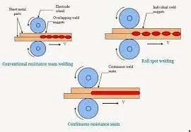
The resistance seam welding is the type of welding where the electrodes will be in the shape of cylinder and the spots will be made in series to make it look like a continuous welds. The welds are connected in this fashion and the local strength of the material will also be increased. The weld will be done through out the seam in series.
Applications :
Containers,Ventilators and Heat ex-changers.
Advantages :
- Gas tight as well as liquid tight joints can be made.
- Simultaneous process and less overlap
Disadvantages :
- Only applicable for straight line or uniformly curved line objects.
- Limited to material thickness of 3mm.
4. What is fusion welding & types of fusion welding with its application in the automotive sector?
Fusion Welding
Fusion Welding is a process of melting two or more metals to join them by heating into melting point of the material.External application of pressure is not required for fusion welding processes, except for resistance welding, where substantial contact pressure is required during welding for sound joining.
Manual Arc Welding :
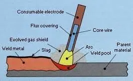
It involves striking an arc between a covered metal electrode and a workpiece. The heat of the arc melts the parent metal and the electrode which mix together to form, on cooling, a continuous solid mass.The arc welding is the process of using consumable electrodes to weld the components and form the desired components.
MIG welding:
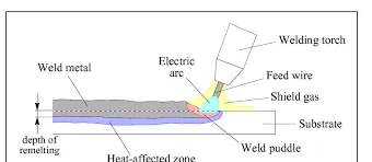
Metal Inert Gas welding is process by which an electric arc forms between a consumable wire electrode and the workpiece leading them to melt and join. Continuous solid wire electrode heated and feed into the weld pool from a welding gun. The gun feeds a shielding gas alongside the electrode helping protect the weld pool from airborne contaminants. Both use a shielding gas to protect the weld from airborne contaminants, or oxidation in the case of MIG welding.
TIG Welding :
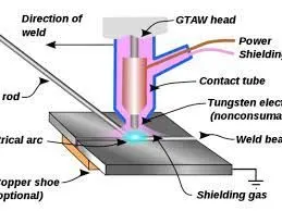
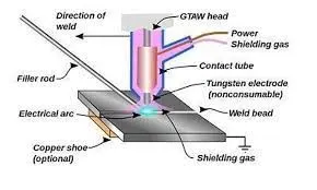
It is also known as Tungsten Inert Gas welding is the process of welding where we use non consumable electrodes to melt two or more metals to join a weld. An arc is formed between a pointed tungsten electrode and the workpiece in an inert atmosphere of argon or helium. ... Because the electrode is not consumed during welding, the TIG welder does not have to balance the heat input from the arc as the metal is deposited from the melting electrode.
Applications of Fusion welding process:
- Aerospace
- Automotive
- Construction
- Manufacturing plants.
- Shipbuilding.
- Industrial piping.
- Railroads.
- Maintenance and repair.
5. What is the 3-2-1 principle?
A fundamental issue with the metalworking process is locating the part to be machined, punched, bent, or stamped relative to the work platform.Hence, the accuracy with which a part is machined is quite dependent on the accuracy with which it is positioned in the fixture. Any variation in part location on the fixture adds to the dimensional tolerance that must be assigned to the finished parts and affect the surface finish of the components. Improper support or clamping can temporarily or permanently deform the part. Hence, techniques for supporting and clamping must be considered together with the method of locating in order to assure repeatability from part-to-part.
Locating of a part to be machined is a three-step process:
1. Supporting
2. Position and Locating.
3. Holding.
Each part have 12 Degrees of freedom among the Translational and rotational axis.
- Translational position along the positive X-axis
- Translational position along the negative X-axis
- Translational position along the positive y-axis
- Translational position along the negative y-axis
- Translational position along the positive z-axis
- Translational position along the negative z-axis
- Clock wise Rotational about the X-axis
- Counter Clock wise Rotational about the X-axis
- Clock wise Rotational about the X-axis
- Counter Clock wise Rotational about the X-axis
- Clock wise Rotational about the X-axis
- Counter Clock wise Rotational about the X-axis
Primary Locators:
First the three locators or supports are placed under the work-piece. It will be positioned on the primary locating surface also known as datum. It will restrict 5 degrees of freedom.
- Axial Movement downward along Z- axis
- CW and CCW Rotation about the X & Y axis
- Axial Movement upward along Z- axis
Secondary Locators
The next two locators are normally placed on the secondary surface, restricting an additional 3 degrees of freedom.
- Axial movement along the +X,-X,+Y, -Y axis
Tertiary Locator
This locator is positioned at the end of the part. It restricts 1 degrees of freedom
- CW and CCW Rotation about the Z axis
All these 6 locators will restrict a total of 9 degrees of freedom. The remaining 3 degrees of freedomare used for loading and unloading the component.
Advantages of 3-2-1 Principle
- Less Cycle time for the process.
- Good surface finish
6. Define Body coordinate system?
A coordinate system is reference system with set of points ,lines and surfaces which is used to define the positions objects in space either two or three dimensions.
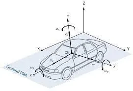
BCS is also called as car line and body line.
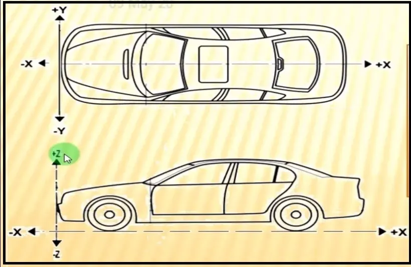
Car lines are the Grid lines virtually represent location of the components in the BIW design with respect to the fixed coordinate system at corner for reference . With these lines one can easily relate the location of the components in BIW design.
Maintaining X,Y & Z co-ordinates in fixture is a very important factor , for performing certain operations like drilling. We should try that the co-ordinates of locating and clamping points should not be in three decimal . Once these co-ordinates are maintained automatically the BIW base structure is maintained.
All vehicle product drawings are identified numerically relative to three vehicle planes Description shown below.
- X axis represent the length of BIW
- Y axis represent the width of BIW
- Z axis represent theHeight of BIW
- –0X is Near Front Bumper and +0X is rear most portion of car
- –0Y is Body Center Line to left most end and +0Y is towards right most end
- -0Z is about Center of Wheel and +0Z is top most portion of the BiW
7. Elaborate Body plane system & its essentials?
Body planes are the reference planes ,which used to define the GD & T of all car parts in an automotive domain. Body planes consists of three mutually perpendicular planes with reference to datum coordinate system.It defines the exact position of each product in the vehicle with respect to a fixed origin.It assists in easy location of different parts in a vehicle with standardised procedure to be followed with different sub sytems and main systems ,all the designs are carried out relative to the bodyline..
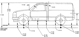
The Measurements from the body planes to the parts are called as bodyline dimensions.
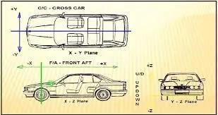
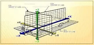
X=Longitudinal direction, which represents the Front & Back (Front O Line - FOL);Length of BIW
Y=Transverse direction, which represents the left and right (center O line - COL);Width of BIW
Z=Vertical direction which represents the Up & Down (Bottom O Line - BOL);Height of BIW
The origin of the body coordinate system (OX) is defined at the front center of a vehicle, it indicates a length of car,the body coordinate system (OY) its starting point is the center of car body indicates width of car and the body coordinate system (OZ) indicates height of car. All vehicle product drawings are identified numerically relative to three vehicle planes