Week 2:- BiW Fixture Basics Challenge
Fixture Basics design
- What is the process of project execution activity?
Execution starts from receiving the RFQ to handling over the fixture setup. There are a lot of steps which are included in between, which are as follows:
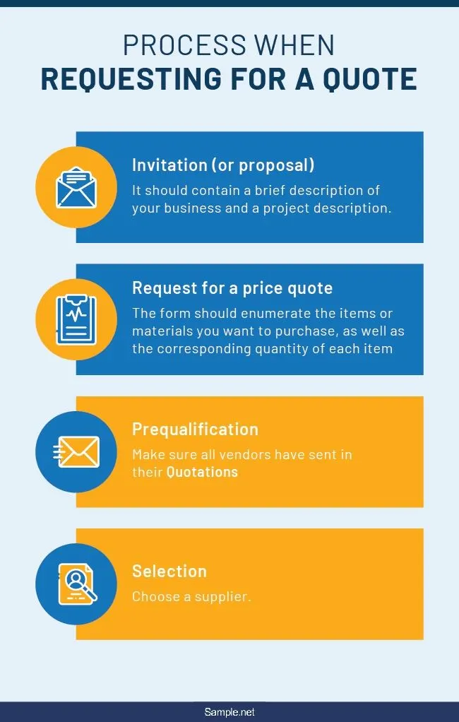
- Request for Quotation (RFQ):
- Before a process can start, the request for specifications and requirements needs to be received from the customers for what and how exactly they need the design to be.
- It includes basic details like when the project needs to be completed, what the offer is along with other details.
- The price and time is usually decided after some discussions.
2. 1st Discussion Meeting:
- After RFQ details of the number of sub-assemblies, geo-tools, simulation validations, drawings etc. are discussed.
- Data study is done, based on that commissions are decided and a technical offer is made.
- Based on technical offer, the commercial offer is done and the project is taken to the next stage.
3. Offer submission:
- The final offer is submitted to the supplier to the customer.
- Meanwhile, the customer checks with other suppliers to decide with which supplier it needs to go with.
4. LOI/PO Receipt:
- The customer finalizes on the supplier and sends in a purchase order.

5. Schedule Preparation:
- After the PO is received, there needs to be a proper schedule maintained for all the work that needs to be done.
- Even if one works gets delayed due to whatever reason, other agendas still need to be tried and completed on the original deadline.
- It is necessary to do so for timely completion of the project.

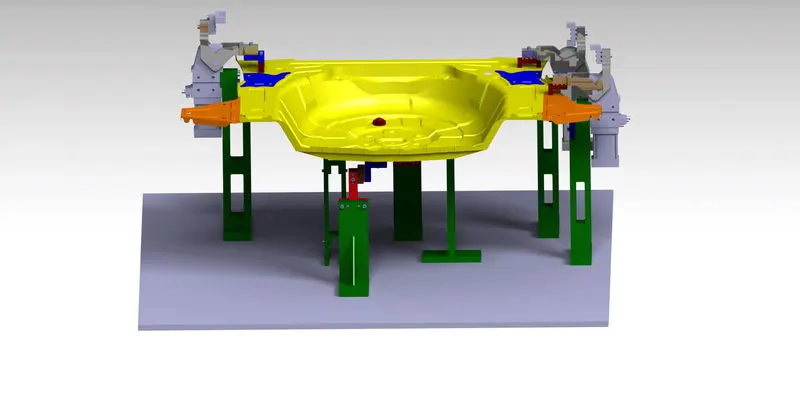
picture not related to Fixtures.
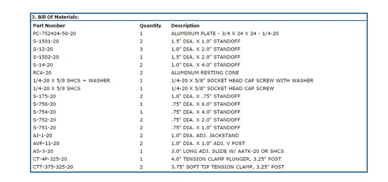
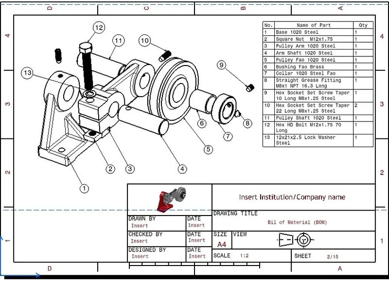
6. BOM Preparation:
- After a certain point, the bill of material needs to be decided.
- The bill usually consists of the cylinders, motors, things that need to be bought out.
- It is made based on the LOI meetings.
7. Design Concept Preparation:
- Before starting on designing, the supplier needs to makes sure they completely understand the customer’s requirements.
- Based on the requirements a basic design sketch is made to get a idea of who the design process should be carried out.
- The design needs to be competent, like the weld guns should not collapse in way through operation.
- To avoid this, load study needs to be carried out, it needs to be kept in mind how many spots need to be welded.
- The spot position and number help decide the reach and number of robots and their sequence of the robots.
- Cycle times study is an important part of design concept preparation.
- It helps give an idea of the time required to performing each operation by each robot and how long will the entire process take.
8. Customer Approval:
- The concept needs to be approved by the customer before moving forward.
- In this step, the customer points out any correction or gives any suggestion if needed.
9. Detailing and Drawing release:
- Once the design is freezed, the detailing is to be done like applying appropriate GD&T.
- These details are necessary before the final design is released.
10. Manufacturing/ BOP ordering:
- The manufacturing according to the design is done in the next step.
- Along with manufacturing, things that are needed to be bought out are also ordered.
11. Mechanical/ Electrical Assembly:
- Once the manufacturing of all the parts is done, quality checks are done on these parts.
- If the parts pass the check, they are used for further assembling.
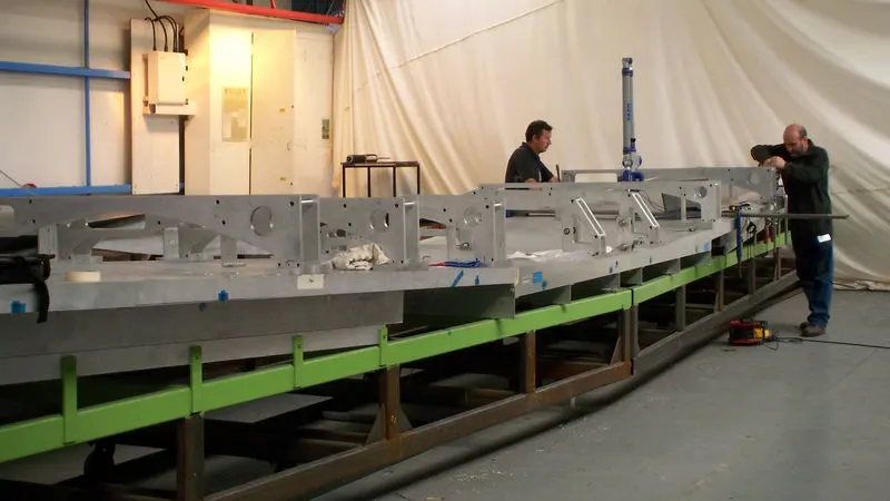
12. Quality Inspection:
- When the parts are assembled, the assembly needs to be checked for correct position of clamps, pins as well as the dimensions are withing tolerance limit.
13. Internal Trial:
- Before dispatch to customer, trails needed to be carried out to check for proper functioning of the fixture.
- Checks are made for whether the clamps hold the job properly, whether the positioning of the pins are correct w.r.t. to the job.
14. Online Trial:
- Trial is done through the control panel.
15. Packaging:
- Once all the checks are done on internal level, the fixture is ready for dispatch.
- For dispatch, the packaging needs to be neat so that the parts aren’t damaged during delivery.
- Some companies have packaging standards and these are to be kept in mind while packaging of the fixture.
16. Dispatch:
- Delivering the package to the customer.
17. Installation as per layout:
- The layout designed during at the initial stage is referred during installation.
- The installation and commissioning team installs the fixture in the right places.
18. Trail and Training:
- Production trails will be taken at customer end.
- During these trails, the number of jobs done is checked with what was listed during the offer.
- Once it is approved, the technicians at the customer end will be trained in using the control panel and the whole process in detail.
- The checkpoints etc. need to be made clear during training.
19. Buy-off meeting:
- Lastly, buyoff meeting is held.
- Any modifications or issues are discussed and sorted out during this meeting.
20. Final Hand over:
- Any documents related to the fixture is handed over during the final step.
- Every company has its own standard of maintaining documents related to the fixtures.
- These documents include, Ergo sheets, BOM, Clamp validation data.
- It is important to have these documents, as they are proof of the work done.
- What are the types of joining processes?
There is various joining process, there are broadly classified into mechanical and metallurgical joining process. The process which needs to be carried out for a particular joint is decided depending on the application.
Metallurgical Joining Process:
Some of the popular joining processes are:
Resistance Welding:
- It is widely used in the manufacturing industry to join two metal sheets.
- In this process, the parts that need to be joined are held together and heated by using a strong current flow. The heat causes the metal to melt and fuse together.
- These fuse points are determined by the electrodes and the design of the parts.
- A force is applied to the workpiece to maintain form or even in some cases when it needs to be forged.

Types of Resistance welding:
- Resistance Spot Welding:
- Electrodes used – Copper chromium, Zirconium alloys.
- These electrodes are used to apply pressure and pass electric current through the sheets held together, for specific amount of time and then dwell.
- The heat generated due to the current melts the metal in the area and thus joins the sheets together.
- A BIW consists of around 5000 spot welds.
- It’s a quick and easy process.
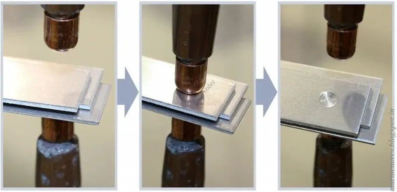
2. Resistance Seam Welding:
- Mostly used when the welding needs to be leak proof.
- Two rollers are rolled over the sheets that needs to be welded together and are provided with electrical charge which melts the sheets as it passes over it and fuses it together.
- Used mostly in radiators, heat exchangers, containers, etc.
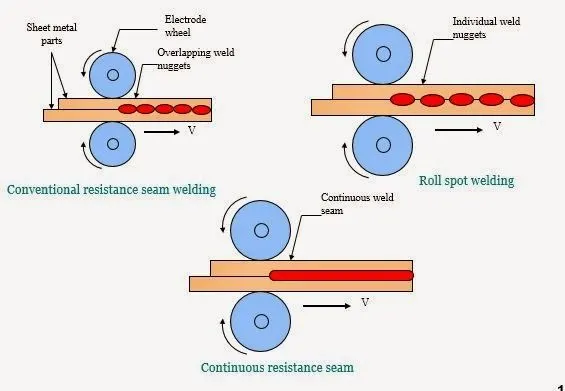
3. Resistance Projection Welding:
- In case of welding sheets with embossing, specialized projected electrodes are required that are in the shape of emboss.
- For these types of welds, Projection welding is done.
- The current and heat generated is restricted to the areas of the weld zone with workpiece shapes or with specialized designed projection.
- Used generally for weld nuts.
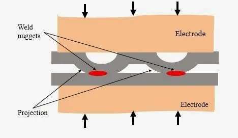
Arc Welding:
- When the weld areas aren’t completely covered by itself and is exposed to the outside environment, arc welding technique is used.
- It usually uses a consumable or non-consumable electrode which has either AC or DC supply provided to it.
Types of Arc Welding Process
- Manual Metal Arc Welding:
- Also called as shielded metal arch welding process.
- It uses a consumable stick to weld.
- A consumable electrode having flux covering is electrically charged and the flux forms a protective covering as the electrode melts and forms a weld pool which eventually cools and welds the workpiece together.
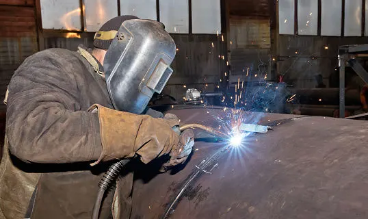
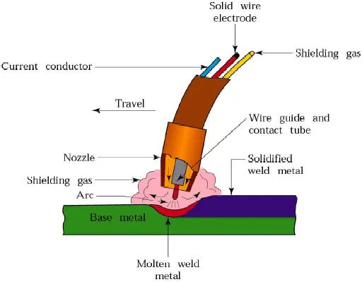
2. Gas Shielded Metal Arc Welding (MIG):
- Also called as metal inert gas welding process.
- The protective covering consists of an inert gas to keep the weld pool free of any impurities.
- The inert gas used is helium gas.
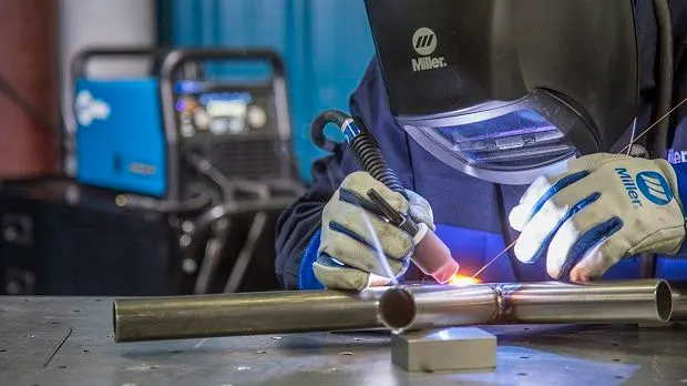
3. Gas Shielded Tungsten Arc Welding (TIG):
- Also called as Tungsten inert gas welding.
- The non-consumable electrode is made of tungsten.
- An external filler rod is required to created the weld pool to join the sheets.
4. Submerged Arc Welding
5. Plasma Arc Welding
Mechanical Joining Process
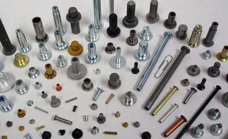
Mechanical Fastening
- For sheets on which welding process cannot be carried out, mechanical joining process is used.
- Sheets like skin surfaces, painted surfaces, etc. cannot be welded together.
- Mechanical fastening is one on the ways of joining such sheets. It is better that welding for joining aluminum sheets.
- Fastening is done for joints that need to last for a long time compared to weld joints.
Self-riveting:
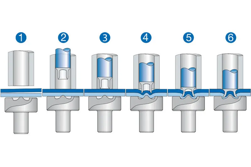
- It’s a high-speed mechanical fastening process.
- It uses semi tubular rivet which to pierce a hole in the sheet.
- The fist hole is created when the rivet is inserted,
- No hole is required unlike conventional riveting process.
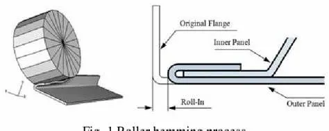
Hemming Process:
- Hemming is a forming process in which a tight fit is obtained from folding a sheet over another at the edges.
- It is one of the important operations where the outer and inner panel are attached together by means of hemming as the outer panel needs to be clean from any kind of spots or defects due to it being a styling element.
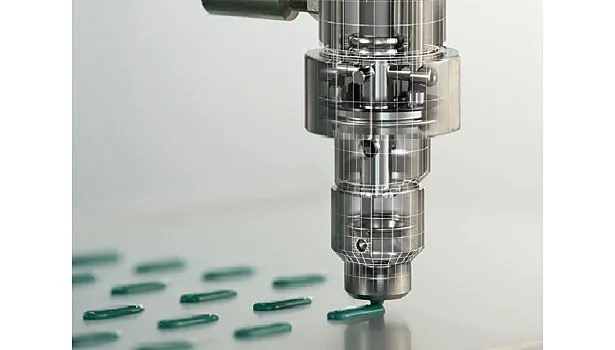
Adhesive Bonding
- A smooth bond is produced uses adhesives.
- The adhesives are usually glues, epoxies, or plastic reagents.
- It is used in joining inner and outer panel to reduce NVH of the vehicle.
- What is Resistance Welding & its application in the automotive sector?
Resistance welding is a liquid weld method. It is a thermoelectric method which is used to join to sheets of metal. It uses electric resistance to generate heat. Heat is generated at the edge planes of welding plates because of electric resistance and a weld joint can be created by applying low-pressure to these plates.
Principle: The principle of resistance welding is generation of heat due to electrical resistance. The types of resistance welding: spot, seam, projection work on the same principle. The generated heat can be used to soften the edge metal to shape a tough weld joint with fusion. This method generates weld with no application of any flux, filler material, and shielding gases.
Types of resistance welding:
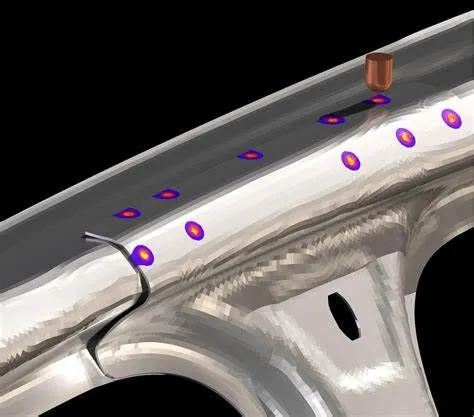
Spot welding:
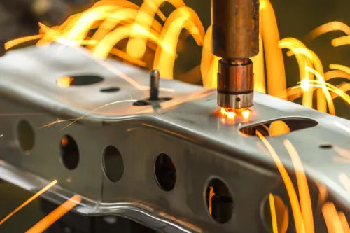
The electrode (mainly copper) is used to hold the workpieces which need to be weld together. Current is supplied to the electrode and the edge surface create a resistance which generates heat. The resistance is maximum at the air gap present between the workpieces. This resistance generates high heat and melts the metal at the edge surface and the current flow is stopped. The electrode is still held over the weld area for it to cool and strengthen.
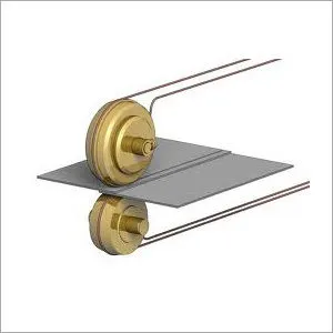
Seam Welding
It can also be understood as continuous spot welding. The electrode is in a form of a roller to make it easy to work on the surface as well as supply current through it. The rest of the working is the same as in spot welding except the electrode keeps moving at a particular speed to create a seam weld. It is used done to create air tight weld areas.
Projection Welding
Similar to spot welding, instead a dimple is generated where weld needs to be done. The workpieces are held together by pressing them together and passing current through it. The current flowing through the dimple dissolves it and the weld is created.
Flash Butt Welding
Uses plastic deformation of the metal to create the weld. A permeant electrode is supplied with current and a changeable electrode brings the workpieces closer and a spart is generated, at the start of plastic deformation, the current flow is stopped.
Advantages
- Simple, does not require an expert.
- No need of flux, filer material.
- Automation is simple.
- Production rate is high.
Disadvantages
- Tool cost high.
- Tensile strength of weld area low.
- Thickness of work section is limited.
Applications:
The amount of spot welds required in automotive sheet metal ranges from about 3000 to 6000. Spot welding is the most important process in automotive industry.
- What is fusion welding & types of fusion welding with its application in the automotive sector?
Similar to resistance welding, it uses heat to weld two surfaces together, but it does not require any external application of pressure and may or not need filler materials.
Types of fusion welding are:
Arc Welding:
Arc welding uses an arc which is supplied with high rated current to join to sheets together. They are usually broadly classified into:
- Shielded Metal Arc Welding (SMAW): Commonly used for welding non-ferrous and ferrous materials in nearly all positions.
- Metal Gas Arc Welding: An electric arc is forming between the material and consumable wire electrode, allowing them to melt and fuse. Shielding gas is used to avoid airborne contaminants and oxidation for MIG welding.
- Tungsten Inert Gas Welding: Non-consumable tungsten is used in creating an arc between the basal plate and electrode. To avoid oxidation and atmospheric contaminations, an inert shielding gas is used.
- Plasma Arc Welding (PAW): In this arc, an electric arc is formed between the torch nozzle and electrode. The argon gas (plasma), usually in the chamber, is ionized by the electric arc.
- Submerged Arc Welding (SAW): It uses a continuously fed consumable electrode together with a flux. The flux prevents spatter and sparks and becomes conductive in a molten state, hence providing the current electrode and material path.
- Flux Cored Arc Welding (FCAW): The process is also continuously fed consumable electrodes with flux; hence it serves as an alternative to SMAW.
Laser Beam Welding
Heat source used is a focused laser beam. The working principle is the same. It’s a fast process, uses light to generate heat.
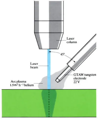
High Energy Welding Process
It uses light radiation as its heat source. To fuse different materials, used light radiation to heat and melt the surface which later cools and fuses together.
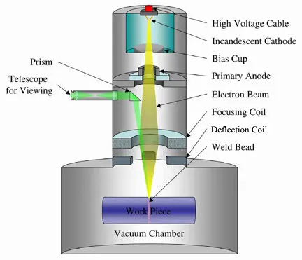
Electron Beam Welding
Uses high velocity electron to melt and join the metal. The electrons when entering in the metal causes heat generation which melts it and joins the surfaces. It can be done in specific environment only.
Friction Welding
Uses mechanically generated friction to join sheets like aluminum, steel etc. It does not require any flux material, shielding gas during operation.
Advantages:
- No need for eternal pressure.
- Fast and straightforward.
- Can join more than two materials together.
- Easy use of filler materials.
Disadvantages:
- Difficult to join material of different melting points.
- Compromises material condition during heating and cooling.
Applications
Arc welding is used for welding parts of frame and chassis. MIG welding is highly used in repair works. For dismantling and assembling parts of an old car.
- 3-2-1 Principle:
When I part is considered in space, it is having 6 degrees of freedom, 3 translational and 3 rotational. These degrees of freedom help locate the position of a workpiece as well as lock its position in space by defining a value to all the 6 degrees.
A fixture needs to be correctly defining with respect to the workpiece in order to get all the weld points right by the robot working on it. Locating and clamping is important for any work holding fixture.
3-2-1 principle for locating is the first step of designing fixtures. It is used for reducing the number of unwanted components and arresting the 6 degrees if freedom of the component. Using the principal, we can lock 3 translational movements of the component and 3 rotational movements.
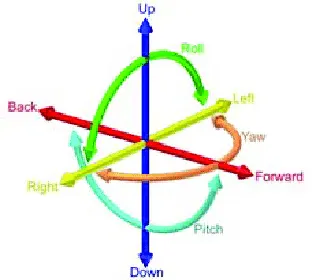
First/ Primary Datum:
- The 3 refers to the first datum which lock 3 degrees of freedom, 1 translational and 2 rotational.
- A minimum of 3 points is required to define this plane.
- For example, rectangular panel is resting on a table. The side which rests on the table is the first plane/datum.
- This restricts the block from moving in an up and down direction and rotating in 2 directions thus locking 3 degrees of freedom (1 translational and 2 rotational)
- Selection: The first plane should be selected such that the 3 points are furthest from each other. Largest surface is to be used for defining the 1st
Second/Secondary Datum:
- This plane is perpendicular to the first datum. If it’s to be defined by points, it needs minimum of 2 points.
- In the above example, if a hole is added to the panel at a point, it restricts 2 more degrees of freedom.
- 2 degrees of freedom locked: 1 translational at is to and fro movement in one direction and the last rotational direction which wasn’t constrained by first plane.
- Selection: The datum must be perpendicular to the first datum.
Third/Tertiary Datum:
- For locking the last degree of freedom, a datum which is perpendicular to the first two datums should be defined.
- In the above example, another hole is introduced in the panel, this restricts the last degree of freedom.
- Selection: Minimum of 1 point is required to define the third datum.
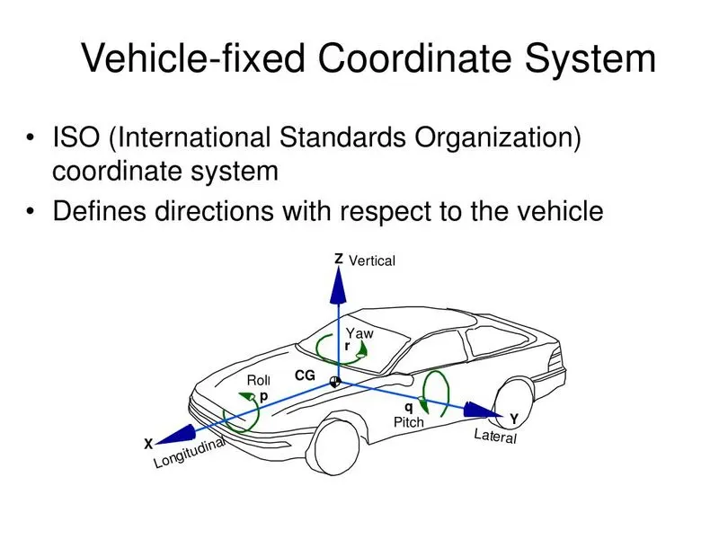
Body Co-ordinate system
It is also known as body line or car line. It is used to locate points in 2 or 3 dimensions. It a reference set of points, which is used to locate line, surface, points on a car body. Different car makers follow different body line standards. The directions are –
- X= Longitudinal direction (FOL – Front ‘O’ Line)
- Y= Transverse direction (COL – Center ‘O’ Line)
- Z= Vertical direction (BOL – Bottom ‘O’ Line)
Elaborate Body plane system & its essentials.
The measurements are called as body line dimensions. These measurements are taken from 3 mutually perpendicular plane and used to define GDnT of all car parts.
It helps define the exact positions of any point on the car body. As, the points can be easily located, errors in the assembly can be greatly reduced. A standardized way is created. It helps in positioning the pins and clamps of fixtures in the right place. Makes works of quality checking easy by defining locations that need to be checked.