Week 2:- BiW Fixture Basics Challenge
- What is the process of project execution activity?
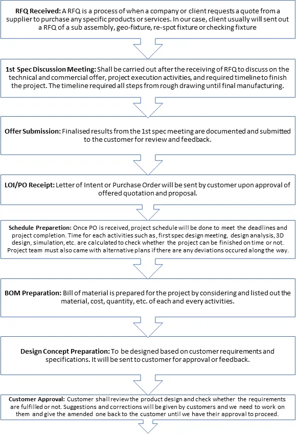
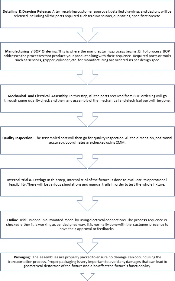
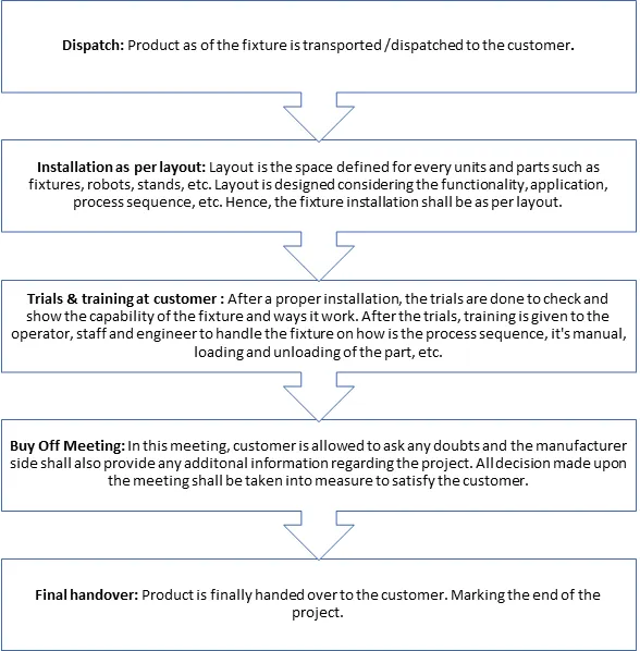
Project execution initiates with the receival of RFQ (Request of Quotation) and ends with final product/service handover to the client. The flow shall be as per below:
- What are the types of joining processes?
Joining process involves two metal parts or different material parts being either temporarily or permanently joined, using either heat, pressure, or another compound. Joining can be done in two types which are the Mechanical joining and Metallurgical joining. Further description shall be as below:
|
Mechanical Joining Is a process of joining using the mechanical methods which involves screws, nuts, rivets, bolts, etc. Mechanical joints must be designed with fatigue failure and brittle fracture to avoid any damages or failed joints. |
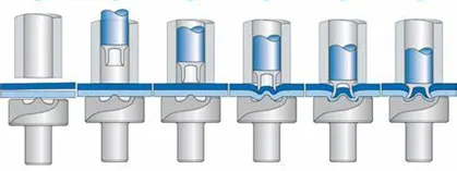
Riveting/Self-Pierced Riveting Permanently or semi-permanently joining two similar or dissimilar metals using rivet which clinches the metal sheets together. It is a fast process as riveting doesn’t need any drilled hole. Riveting is used at parts or area that doesn’t allow any welding or bolting to be done considering the material or aesthetic aspects. It is widely used in automotive industry.
Figure above shows the process of self-pierced riveting |
|
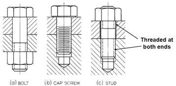
Bolting Temporary join process to assemble different parts that usually require periodic maintenance. This process uses bolt & nut or screw.
Figure above shows the inserted bolt, cap screw and stud |
|
|
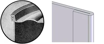
Hemming/Seaming Hemming is a metal working process where the edge of the metal sheet/part is rolled over into itself, while seaming joins the edge of two materials using the same method.
Figure above shows the seaming (left) and hemming (right) method |
|
|
Metallurgical Joining It joins two metals that involves metallurgical changes. Usually, metals will be fused or heated, or filler materials may be added. |
Welding A joining process in which the work pieces are fused together by means of heat, pressure or both, forming a join between the pieces. Welding can be categorised into two:
In automotive sector types of welding that are commonly used are Metal Inert Gas Welding (MIG), arc welding, Tungsten Inert Gas Welding (TIG), Flux Core Welding. |
|
|
Brazing
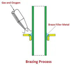
Joining parts using a filler material that filled between and undergoes melting process. The temperature for brazing shall be high enough to melt the filler material only. Materials used as fillers for brazing have melting point of 450 °C. Flux is also used in this method to eliminate oxide films from the surfaces of the work pieces and to prevent oxidation. A strong joint s obtained after the brazing material has cooled down. |
|
|
Soldering
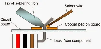
Solder is melted by using heat from an iron connected to a temperature controller. It is heated up to temperatures beyond its melting point which then causes it to melt, then cools down creating the soldered joint. Soldering use filler metal such as tin-lead, brass, lead-silver, and copper. |
|
|
Adhesive Bonding Used to fasten two surfaces together that usually producing smooth bond. This technique involves glues, epoxies, or various plastic agents that bond by evaporation of a solvent or by curing the adhesive agent with heat, pressure or waiting time. Adhesive-bonded joints can withstand shear, tensile, and compressive stresses, however they do not exhibit good resistance against peeling. Hence, rough surfaces can improve this kind of bond strength due to the mechanical interlocking.
Figure 4 shows the adhesive bonding machine |
|
|
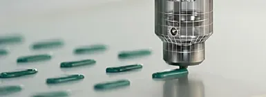
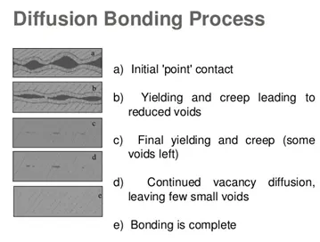
Diffusion Bonding Diffusion Bonding is a solid-state joining process which is applicable to similar and dissimilar materials, primarily metals. The process works through the diffusion of atoms across the joint interface at elevated temperature. Diffusion bonding does not require any filler materials, and for a similar materials joint, it is completely autogenous. The diffusion boding method is widely used in the joining of high-strength and refractory metals within the aerospace and nuclear industries. |
- What is Resistance Welding & its application in the automotive sector?
|
Resistance Welding |
A welding process where metal parts in contact are permanently joined by heating them with an electric current, melting the metal at the joint. A force is always applied before, during and after the application of current to confine the contact area or to forge the workpieces. Type of resistance welding
|
|
- Resistance Spot Welding |
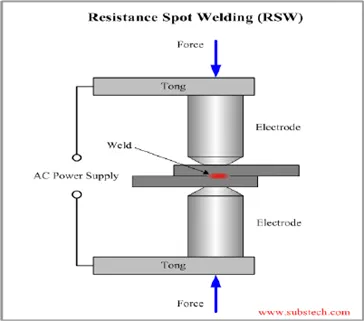
RSW is done in spots. These spots are marked beforehand at required intervals. The workpiece is placed between the electrodes and as the current power supply flows and force is asserted results in slightly melting spot and joining the workpieces.
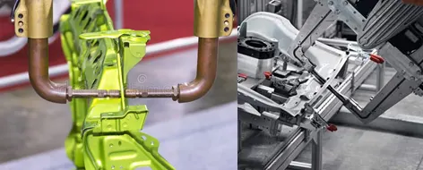
Figure above shows the Resistance spot welding in automotive industry RSW is an important process in the automotive industry. The advantages of spot welding are many: an economical process, adaptable to a wide variety of materials (including low carbon steel, coated steels, stainless steel, aluminium, nickel, titanium, and copper alloys) and thicknesses, a process with short cycle times, and overall, a relatively robust process with some tolerance to fit-up variations. |
|
- Resistance seam welding |
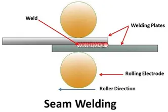
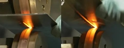
Resistance seam welding (RSEW) is a resistance welding process for joining metal sheets in continuous, often leak tight, seam joints by directly applying opposing forces with electrodes consisting of rotary wheels. The current and the heat generation are localized by the peripheral shapes of the electrode wheels. Same with other types of resistance welding, fusion is produced where the sheet surfaces come into contact due to this being the point of highest electrical resistance and thereby the place where heat generation is at its greatest. The heat from the disc-shaped electrode wheels creates a continuous weld as the work pieces are fed between them, resulting in a rolling resistance weld. Figure above shows the seam welding on two metal plates in automotive industry In automotive sector, parts such as fuel tanks, gas tanks, and other liners or edges uses RSEW as it welds resulting no gaps or spaces. This type of weld perfectly elas the part and is suitable to weld the leak pfroof components. |
|
- Resistance projection welding |
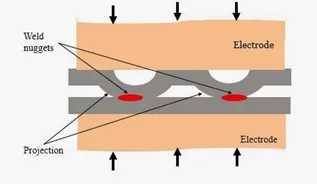
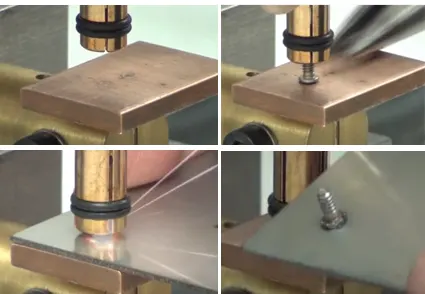
Resistance projection welding (RPW) is a bit similar to the resistance spot welding. The current & heat generation are localized by shape of workpieces either with their natural form or specially designed projection. Projection electrodes are capable of carrying more current than spot welding electrodes and can, therefore, weld much thicker materials Projection welding offers benefits such as:
Figure above shows the cap screw that welded onto a metal piece using the RPW method
|
- What is fusion welding & types of fusion welding with its application in the automotive sector?
|
Types |
Description & Application |
|
|
Arc Welding |
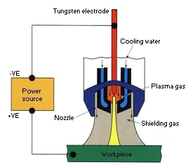
Uses an electrode (consumable/non-consumable) to weld two components. The arc produced between the electrode and workpiece using AC/DC supply, welds the two components together. arc will generate enough heat to melt the electrode and areas of the work pieces. Molten metal of the electrode and molten metal of the work piece will combine forming a strong join after its solidified. Below are the types of arc welding that commonly used in automotive sectors. There are 4 types of welding processes: a) Gas Metal Arc Welding (GMAW/MIG) b) Gas Tungsten Arc Welding (GTAW/TIG) c) Shielded Metal Arc Welding (SMAW) d) Plasma Arc Welding |
|
|
A |
Gas Metal Arc Welding, GMAW |
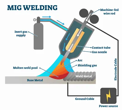
GMAW or Metal Inert Gas (MIG) welding shields the arc with a gas like argon or helium or a gas mix. The electrodes have deoxidizers that prevent oxidation, so you can weld multiple layers. This method has several benefits: simple, versatile, economical, low temperatures, and easily automated. This is a popular welding technique for thin sheets and sections. This welding method is used in the joining of bone, chassis area and engine parts in automotive industry. |
|
B |
Gas Tungsten Arc Welding, GTAW |
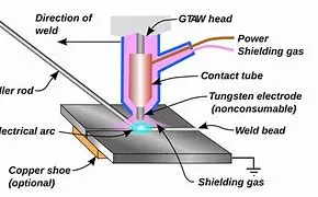
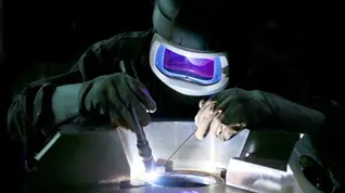
GTAW or Tungsten Inert Gas (TIG) welding, is often considered to be the most difficult. Tungsten electrodes create the arc. Inert gases like argon or helium or a mix of the two is used to protect the shield. Filler wires add molten material if needed. This method is much “cleaner” as it doesn’t produce slag, making it ideal for welding jobs where appearance matters as well as thin materials.
Figure 8 shows the TIG welding in real time GTAW/TIG welding is most commonly used to weld thin sections of stainless steel and non-ferrous metals such as aluminium BIW structures in automobile. |
|
C |
Shielded Metal Arc Welding (SMAW) |
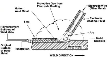
SMAW is one of the simplest, oldest, and most adaptable arcs welding methods, making it very popular. The arc is generated when the coated electrode tip touches the welding area and is then withdrawn to maintain the arc. The heat melts the tip, coating, and metal, so that the weld is formed once that alloy solidifies. This technique is typically used in pipeline work, shipbuilding, and construction. This welding process also being used in automotive sectors, as example the joining of base parts of chassis and doors of the automobiles. |
|
D |
Plasma Arc Welding |
Plasma welding is very similar to TIG as the arc is formed between a pointed tungsten electrode and the workpiece. However, by positioning the electrode within the body of the torch, the plasma arc can be separated from the shielding gas envelope. Plasma is then forced through a fine-bore copper nozzle which constricts the arc. Three operating modes can be produced by varying bore diameter and plasma gas flow rate:
For automotive industry, plasma arc welding/cutting was used for high-speed purposes. It is widely used to weld pipes and tubes of stainless steel or titanium |
- What is the 3-2-1 principle?
This 3-2-1 principle is used to constraint the movement of the workpiece along the three axes XX, YY and ZZ. There are 12 degrees of freedom in total acting on these three axes which needs to be restricted in order to get a good fixture design and order to achieve that this 3-2-1 is known as the locating point which are 3 pins in base plate, 2 pins in vertical plane and 1 pin in a plane which is perpendicular to first two plane.
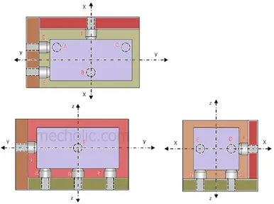
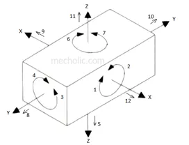
Referring to above pictures using this method, 12 degrees of freedom is controlled.
Pins A, B, C on the base plane (a plane parallel to the plane which contains X and Y axis) restrict the rotation of component about X axis and Y axis. It also limits the downward movement of component along z axis. Ie. 1,2,3,4 and 5 degrees of freedom is restricted.
Pins D, E is in plane parallel to the plane containing X and Z axes. It prevents the rotation of component about Z axis (6, 7 degree of freedom) and the movement of the body in along Y axis towards one direction (8 degree of freedom).
The last pin F is in a plane parallel to plane contains Y and Z axes. It restricts the movement component along X axis in one direction.
Three remaining degree of freedom 10, 11, 12 is unrestricted. It facilitates the loading of the component in the fixture. These three degrees of freedom may restrict after loading of component by using clamping devices. Hence, all 12 degree of freedom is now restricted.
- Define Body coordinate system?
Body coordinate system, BCS is commonly used in the automotive industry for drawing of body parts, product, and process design. A coordinate system is a reference system that consist of a set of points, lines and surfaces used to define the positions of points in space either in two or three dimensions.
BCS are used to locate the position of part or panel of a car. it is also called as car line and body line.
Car lines are the grid lines shown on the fixture, which virtually represent the same location as in BIW. All the car line on fixture displays the coordinate at corner for references. Figure below picture shows the grid line on the fixture:
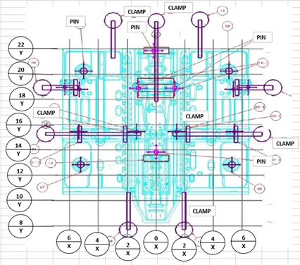
Maintaining X, Y & Z co-ordinates in fixture is a very important factor.
We should try that the co-ordinates of locating and clamping points should not be in three decimals (e.g., X=100.124, Y=245.127, Z=450.458).
They should be in the whole nos. or max up to 1 decimal. Once these co-ordinates are maintained automatically the BIW base structure is maintained.
All vehicle product drawings are identified numerically relative to three vehicle planes Description shown below.
- (X) It is in width of BIW – 0 X - is Body Centre Line
- (Y) It is in length of BIW – 0 Y is Near Front Bumper
- (Z) It is in Height of BIW - 0 Z is about Centre of Wheel
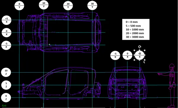
Figure above illustrates a typical body coordinate system.
- Elaborate Body plane system & its essentials.
Body planes are the references planes in an automotive car. These planes are used to define the geometry, dimension, and tolerance of all car parts in an automotive domain.
Body planes are 3 mutually perpendicular and the measurement from body plane to parts are called as body line dimensions:
FOL Front “O” line. Measurement along FOL / X-axis is called F/A Front aft.
COL Centre “O” line. Measurement along COL / Y-axis is called as C/C Cross car.
BOL Body “O” line. Measurement along BOL / Z-axis is called as U/DUP down.
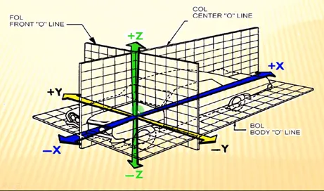
Figure above shows the typical body planes of the car
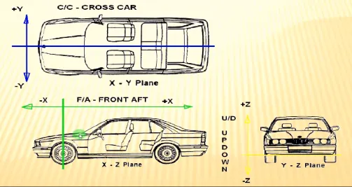
Figure above shows the XX, YY, ZZ body planes of the car
Below are the essentials of the body plane:
- It defines exact position of each product in the vehicle w.r.t. a fixed origin.
- It ensures flawless design for assembly.
- While designing lines, all designs are carried out relative to the bodyline, viz, fixture, turn table etc.
- It assists in easy location of different parts in vehicle.
- It aims in creating a standardized system.
- It assists in quality checks.