Week 2:- BiW Fixture Basics Challenge
1) What is the process of project execution activity?
Answer:
RFQ:
Request for quotation
In this where the customer gives the requirments in detail for the given projects in the form of data or documents.
Also, the customer specifies its technical offer, commercial offer etc., how the project will be excecuted and the timeline of the project also will be mentioned.
Discussion meeting;
After rfq received, technical offer , commercial offer, a timeline of the project etc., will be discussed and prepared from outside.
Based on the technical offer the commercial offer will be finalized.
Offer submission;
After the finalization in the meeting, the offers will be submitted to the customer end.
Customer will arrange to get an offer from other suppliers too.
Based on the technical, cost ,quality, standard and name in the industries, the customer will be finalizing the offer.
LOI/PO Receipt;
Here customer will be releasing the LOI/PO purchase order
Once PO is released we have to start the work.
After getting PO from the customer we have to prepare the schedule.
Schedule preparation;
Once the PO released from the customer we will be working on preparation of schedule which should be matched our planned commitment in the technical offer customer required time.
BOM preparation
Bill of materials like cylinders , motors etc., which is required for the project are prepared.
Design concept preparation
Before the design concept we have to study the data of the customer requirement thoroughly which is carried out in design data study activities.
During the design data study, we will proceed with rough sketches to get a flow while designing concepts.
In this concept preparation, we should conceptualize the basic data like spot plan, cycle time etc.
Customer approval;
It is also known as the design approval process.
After design concepts the customer will review the design concepts.
- Detailing &Drawing release;
The detailing of the fixture parts which is to be manufactured has been done with given appropriate dimensions and GD&T symbols.
All the dimensions which are the necessity for manufacturing should be included with gd&t in the drawings before releasing the drawing to the manufacturing team.
Manufacturing/BOP ordering;
The mechanical and electrical parts like sensors, cylinders. Etc., which needs for a fixture or ordered as per the design specifications.
Mechanical/ Electrical assembling;
After the materials ordered received to our end. The quality will check the working conditions and technical specs. Which meets our requirements.
After they will be assembled as per the design.
Quality Inspection;
In all dimensions, positional accuracy, coordinates are checked using CMM.
Internal Trial;
After QC check internal trials are made to check the operation of the fixture.
It is a first trial taken in house, the pins are getting into holes, clamping operation, assembly /panel suited correctly etc.
Online Trail;
The trail will be done in automatically made through the control panel.
The process sequence of operations is checked as by the designed way.
Packaging;
To avoid damage occur in fixtures while transporting which may also lead to affect the aesthetic look & proper function of fixture packaging has been done.
After approval of QC ,packaging is been done as per standards, so packaging should be one as per standards.
Dispatch;
After the fixture has been packed for delivery as per standards.
Its been dispatched to the customer.
Installation as per layout;
The design of the layout are been prepared at a very initial level which gives the information of placements of robots and fixtures.
According to the design the installation and commission team will install the fixtures.
Trails & Training at customer;
Production trails will taken at the customer end.
The checkpoints which has to be done after placing the panels into the fixture will be made clear to them.
Buyoff meeting;
In this meeting customer will give reviews about the fixtures, sometimes customer may need to do some additional work also. It will be discussed and finalize in the meeting.
Final handover:
The fixture and the documents support the fixture will be handed over.
Documents like clamp validation documents, ergo sheets, BOMs , charts will delivered to the customers.
Every automobile industries will follow some standards to maintain the documents as per ISO, IATF.
2)What are the types of joining processes?
Answer:
Assembly is an important step for manufacturing solid products, especially when the shape of the product is complicated having multifarious geometrical features. It is neither feasible nor economical all the times to directly produce a product having intricate shape. In such scenario, making small simple parts and joining them together is the best possible way.
Joining consists of a large number of processes used to assemble two or more parts together, irrespective of their composition, properties, features, shapes, etc.
By definition, joining is one of the manufacturing processes by which two or more materials can be permanently or temporarily joined or assembled together with or without the application of external element in order to form a single unit
Types of Joining
Joining processes are typically divided into three categories
- Mechanical joining
- Welding
- Chemical joining
Mechanical Joining
- Mechanical joining – also called joining by forming – has become interesting for the automotive industry due to the request to reduce fuel consumption and thereby emissions.
- In order to reduce weight on the car body, the usage of lightweight materials in the body-in-white application has increased.
- This includes aluminium, high-strength steel alloys, polymers, and composites.
- Here the different type of mechanical joining becomes important.
- All mechanical joining methods are cold forming techniques.
- One general benefit for all mechanical joining methods is the mobility of the Material after joining. At the same time mechanical joining offers an impressive strength.
Types of Mechanical Joining
- Riveting
- Bolting
- Hemming
Riveting
- Riveting is a forging process that may be used to join parts together by way of a metal part called a rivet.
- The rivet acts to join the parts through adjacent surfaces.
- A straight metal piece is connected through the parts. Then both ends are formed over the connection, joining the parts securely.
Bolting
- In this metal joining process, the metallic parts are joined together by means of Bolt/Screw.
- This Process is widely used in assembling of parts are to be joined temporarily or joints which require periodic maintenance.
- Two main types of loads on bolted joints - Tension Shear Bolting.
Hemming
- Hemming is a forming operation in which the edges of the sheet are folded or folded over another part in order to achieve a tight fit.
- Normally hemming operations are used to connect parts together, to improve the appearance of a part and to reinforce part edges.
Welding
- Welding is a fabrication process that joins materials, usually metals or thermoplastics, by using high heat to melt the parts together and allowing them to cool, causing fusion.
- When heated or pressurized for a certain amount of time, metal starts melting.
- By melting the adjoining sections of two materials to be joined (base material or filler material) to make them blend together to form penetration and then cooling that section, you can join materials into one piece.
- This is the basic mechanism of welding.
Types of Welding process
Chemical Joining
This type of joining comprise of Adhesive bonding.
Adhesive bonding
- Adhesive Bonding is the process of joining two surfaces together, usually with the creation of a smooth bond.
- This may involve the use of glue, epoxy, or one of a wide range of plastic agents which bond either through the evaporation of a solvent or through curing via heat, time, or pressure.
3) What is Resistance Welding & its application in the automotive sector?
Answer:
Resistance welding allows welders to join two metal workpieces together by employing the principle of heat generation through electric resistance.
An electric current is passed to the metal sheets through weld electrodes that apply force to the sheets.
The key advantage of resistance welding is that no other materials are needed to create the bond, which makes this process extremely cost effective.
Resistance welding machines are designed and built for a wide range of automotive, aerospace and industrial applications. Through automation, the action of these machines is highly controlled and repeatable allowing manufacturers to staff production readily.
Types of Resistance Welding
The various types of resistance welding are
- Spot resistance welding.
- Seam resistance welding.
- Projection resistance welding.
- Flash resistance welding.
- Butt resistance welding
Spot Welding
- In this process, the parts to be joined are held firmly between two heavy electrodes, which are connected in the secondary circuit of the step-down transformers.
- he maximum resistance exists at the contact surface of the two parts being joined and high heat is developed.
- The heat developed fuses the workpiece at the electrode spot.
- At the same time pressure is applied to the workpiece through the electrodes and welding takes place.
- Current supply and amount of time must be sufficient for proper melting of interface surfaces.
- The current stopped flowing but the pressure applied by the electrode remained for a fraction of a second, while the weld cooled rapidly.
- Subsequently, the electrode is removed and brought to contact another location.
- This will form a circular nugget and its size depends on the size of the electrode.
Seam Welding
- Similar to spot welding but in this a continuous weld is produced by passing the work between rotating wheel-shaped electrodes, which exert the welding pressure and also conduct the welding current.
- Seam welding may be continuous or intermittent.
- First, the rollers are exposed to the workpiece.
- A high amount of ampere current is passed through these rollers.
- This interface surfaces will melt and form a weld joint and the rollers start rolling on the work plates.
- This will form a continuous weld joint.
- The movement time of the weld and electrode is controlled to assure that the weld overlaps and the workpiece is not too hot.
- Seam welding is used to make airtight joints.
Projection Welding
- Like other Resistance Welding Processes, Projection Welding uses heat generated by resistance to the flow of welding current, as well as force to push the workpieces together, applied over a defined period of time.
- Projection Welding localizes the welds at predetermined points by using projections, embossments or intersections, all of which focus heat generation at the point of contact.
- Once the weld current generates sufficient resistance at the point of contact, the projections collapse, forming the weld nugget.
- Solid Projections are often used when welding fasteners to parts.
- Embossments are often used when joining sheet or plate material.
- An example of Projection Welding using material Intersections is cross-wire welding.
- In this case the intersection of the wires themselves localizes heat generation, and therefore resistance.
- The wires set-down into one another, forming a weld nugget in the process.
Flash Welding
- Like other Resistance Welding Processes, Flash Welding uses heat generated by resistance to the flow of welding current, as well as force to push the workpieces together, applied over a defined period of time.
- Flash Welding is a Resistance Welding Process which generates resistance using flashing action.
- This action is created using very high current density at very small contact points between the workpieces.
- At a predetermined point after the flashing process has begun, force is applied to the workpiece, and they are moved together at a controlled rate.
- Rapid upset created by this force expels oxides and impurities from the weld.
Butt Welding
- The butt welding differs from flash welding, in that no arcing takes place between the surfaces being joined.
- The heat is produced solely by the electric resistance at the butting surface to the flow of current.
Advantages of Resistance welding
- No filler metal is required.
- Similar and dissimilar metals can be welded.
- High skilled labour is not needed because of the simple and fully automated process.
- It has a high production rate.
- It is an environmentally friendly process.
- This process has a high welding speed.
Diasdvantages of Resistance welding
- The equipment cost of resistance welding is high.
- The thickness of the workpiece is limited due to the current demand.
- It is less suitable for high conductive materials.
- It has a high electric power required.
- The weld joints have low tensile and fatigue strength.
Applications in Automotive sector
- Resistance welding has a wide range of applications in Automotive sector such as BIW features.
- It is used in the welding of metal doors.
4) What is fusion welding & types of fusion welding with its application in the automotive sector?
Answer:
Fusion welding is the welding process in which two or more materials of similar composition or melting points are joined or fused with each other by melting the materials.
In many of the fusion welding processes, the filler material is added to the molten pool of metal required but some fusion welding can be carried out without using the filler material.
The filler material is added to increase the strength of the weld joint.
The welds made without filler materials are called autogenous welds.
If the filler material used and the parent material are the same, then the weld produced in this type of welding is called homogeneous weld.
If the filler material used and the parent material are different, then it is called a heterogeneous weld.
Types of Fusion Welding
The various types of fusion welding are
- Arc Welding
- Oxy-Fuel Welding
- Laser Beam Welding
- Thermit welding
- Induction Welding
Arc Welding
- Arc welding refers to the group of welding processes in which the metals are heated to melting points by an electrical arc.
- In some arc welding processes pressure is also applied to the workpiece for better weld strength and quality.
- Most of the arc welding process makes use of filler material.
Arc Welding is further classified into the following types,
- Shielded Metal Arc Welding (SMAW)
- Submerged Arc Welding (SAW)
- Tungsten Inert Gas Welding (TIG)
- Metal Inert Gas Welding (MIG)
- Plasma Arc Welding (PAW)
Shielded Metal Arc Welding (SMAW) - It is also known as manual metal arc welding (MMA or MMAW), flux shielded arc welding or stick welding. Suitable for welding ferrous and non-ferrous materials in all positions.
Metal Inert Gas Welding (MIG) - It isalso known as Gas Metal Arc Welding (GMAW). MIG and MAG welding are the most common arc welding processes, in which an electric arc forms between a consumable wire electrode and the workpiece leading them to melt and join. Both use a shielding gas to protect the weld from airborne contaminants, or oxidation in the case of MIG welding.
Tungsten Inert Gas Welding (TIG) - It is also known as Gas Tungsten Arc Welding (GTAW). This arc process uses a non-consumable tungsten electrode to create the arc between the electrode and the base plate. An inert shielding gas is used to protect from oxidation or other atmospheric contamination. This process can be used autogenously on thin parts, but will require the addition of a wire, rod, or consumable to be added for thicker parts.
Plasma Arc Welding (PAW) - This process uses an electric arc created between an electrode and the torch nozzle. The electric arc ionises the gas (usually argon) in the chamber creating what is called a 'plasma.' It is then forced through a fine bore copper nozzle that constricts the arc and directs it to the workpiece, allowing the plasma arc to be separated from the shielding gas (which is usually made from a mixture of argon and hydrogen).
Submerged Arc Welding (SAW) - This frequently-used arc welding process uses a continuously-fed consumable electrode and a blanket of fusible flux which becomes conductive when molten and provides a current path between the workpiece and the electrode. The flux also prevents spatter and sparks while suppressing ultraviolet radiation and fumes
Oxy-Fuel Welding
- Oxy-fuel welding is the type of welding process in which oxygen is used as fuel to produce a flame that heats and joins two metal surfaces.
- This process is also known as oxy-acetylene welding.
- This welding process uses a combination of oxygen and a flammable gas mostly acetylene to create a hot flame to join objects.
- Oxygen and fuel are mixed in the right proportion within a handheld torch or blowpipe to produce a hot flame with a temperature of about 3200 degrees Celcius.
- As steel melts at 1500 degree Celcius, this is the only welding process which can produce such high temperature by combining oxygen and acetylene to melt steel.
- So steel can be welded using this welding process only. While other non-ferrous metals with low melting points can be welded by using a mixture of oxygen and gases like hydrogen, propane, or coal gas in the oxyfuel welding process.
Laser Beam Welding
- Laser Beam Welding is a fusion welding process in which two metal pieces are joined using a laser.
- Laser Beam Welding is done by focusing the laser beam to the cavity between the two metal parts.
- The laser beam strikes the metal parts and produces heat which melts the material of the two metals or the filler material.
After cooling of the molten metal, a weld is formed which is very strong.
Thermit welding
- Thermite welding is a welding process in which a thermite compound is used to weld two metals together.
- Thermite is a type of chemical composition of a metal powder.
- Powder normally consists of a metal and a metal oxide.
- When this powder is ignited, it undergoes an extremely exothermic redox reaction.
- Here oxide from one metal transfers to the other metal. In this welding process, a huge amount of heat is generated for a brief period.
- The most common use of thermite welding is to join rail tracks in railways.
- This process does not require any heavy machinery and is very fast.
- This process is also used to repair rail tracks as the molten metal from the reaction can be used to repair the tracks.
Induction Welding
- In Induction welding process, electromagnetic induction is used to heat the metal surfaces which are to be joined.
- An induction coil is present in the welding apparatus which is energized with a radio-frequency electric current.
- This welding process is mainly used to weld materials that are either electrically conductive or are ferromagnetic materials.
- Electrical insulators and non-magnetic materials can also be welded using this process by implanting them with ferromagnetic or metallic compounds called susceptors.
Advantages of Fusion welding
- Fusion Welding can be used to join dissimilar materials easily.
- External filler material can be added easily.
- No external pressure is needed.
- Using this process, more than two components can be welded at a step.
Disadvantages of Fusion welding
- Due to intense heating and subsequent melting, many mechanical and metallurgical properties are affected.
- Because of excessive heat input, high distortion takes place.
- Noticeable heat affected zone exists around the weld bead due to excessive heat.
- Welding two dissimilar metals is difficult specially if the metals have different melting points and coefficient of thermal expansion.
Applications in Automotive sector
- It is used to weld the parts of chassis.
- It is used in joining the wheel base.
5) What is the 3-2-1 principle?
Answer:
3-2-1 Principle of Location used in Jig & Fixtures:
It is also known as a six-pin or six-point location principle. In this, the three adjacent locating surfaces of the blank (workpiece) are resting against 3, 2, and 1 pin respectively, which prevent 9 degrees of freedom.
The rest three degrees of freedom are arrested by three external forces usually provided directly by clamping.
3-2-1 Principle Statement :
The 3-2-1 principle states that the six locators are sufficient to restrict the required degree of freedom of any workpiece. In this, motion is restricted using clamps and locators. A three-pin base can restrict five motions and six pins restrict nine motions.
Methodology of 3-2-1 Principle:
For this, refer the below figure;
[1] The workpiece is resting on three pins A, B, and C which are inserted in the base of the fixed body.
[2] The workpiece cannot rotate about the axes XX and YY and also cannot move downward.
[3] In this way, the five degrees of freedom 1,2,3,4 and 5 have been arrested.
[4] Two pins D and E are inserted in the fixed body, in a plane perpendicular to the plane containing pins A, B & C.
[5] Now the workpiece cannot rotate about the Z-axis and also it cannot move towards the left.
[6] Hence the addition of pins D and E restrict three more degrees of freedom, namely 6, 7, and 8.
[7] Another pin F in the second vertical face of the fixed body, arrests degree of freedom 9.
The above method of locating a workpiece in a fixture is called the 3-2-1 Principle.
Summary of 3-2-1 Principle:
A workpiece will be completely confined when blanked against:
- 3 points in one plane: The “3” in 3-2-1 refers to 3 locators (passive fixture elements) on the primary locating/datum surface.
- 2 points in another plane: The “2” in 3-2-1 refers to 2 locators on the secondary locating/datum surface.
- 1 point in a third plane: The “1” in 3-2-1 refers to 1 locator on the tertiary locating/datum surface
6) Define Body coordinate system?
Answer:
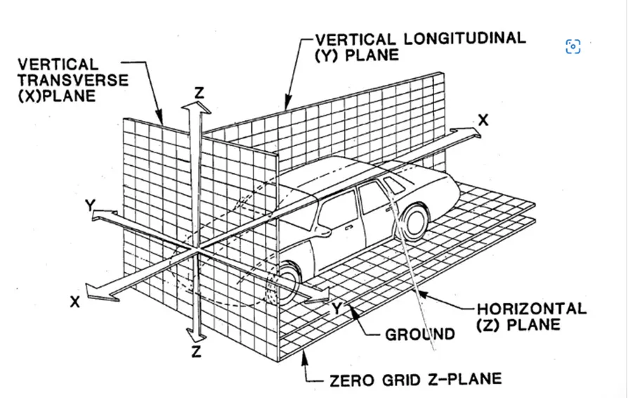
Body coordinate system is used in the automotive industry for drawing of body parts and product design.
Coordinate systems are used to describe the position of an object in space.
A coordinate system is an artificial mathematical tool that we construct in order to describe the position of a real object.
It can also be knwon as Car line and Body line.
Car lines are the (Grid lines) shown on the fixture, which virtually represent the same location in the BIW. All the car line on fixture display the coordinate at corner for reference. With these lines one can easily relate the, location in BIW.
X = Longitudinal direction (Front O Line - FOL)
Y = Transverse direction (Center O Line - COL)
Z = Vertical direction (Bottom O Line - BOL)
7) Elaborate Body plane system & its essentials.
Answer:
Body planes are reference planes in automotive car.
These planes are used to define the GD & T of all car parts in automotive domain.
It helps in creating a standard system to work with.
It helps in locating various parts in an easy manner.
It helps in ease of access.
The measurement along FOL or X axis is known as F/A or Front Aft
The measurement along COL or X axis is known as C/C or Cross Car
The measurement along BOL or X axis is known as U/d or Up Down