Week 2:- BiW Fixture Basics Challenge
Q1. What is the process of project execution activity?
Answer :- The process of project execution activity are follows:-
- RFQ Received :- RFQ stands for request for quotation. First of all the RFQ is raised as per the requirement.
- First spec. discussion meeting:- Both supplier and customer do the meeting for all the clarity about the process and product.
- Offer Submission:- After the first spec. Discussion, offer is submitted, in which all the cost is calculated.
- LOI/PO Receipt:- PO stands for purchase order and LOI stands Letter of intent. After the offer submission PO is generated from the supplier for the customer.
- Schedule Preparation:- Schedule is prepared for the all the process from all the steps child parts to assembly.
- BOM Preparation :- BOM stands for Bill of material. BOM consists of the no of parts, no of parts, cost of parts and how much parts are required for the manufacturing of the assembly.
- Design Concept preparation:- Cad model is prepared as the requirement and drawings are released and controlled.
- Customer Approval- After making all the drawings, they are sent to the customer for their approval.
- Detailing and drawing release:- Drawings are controlled and then are released.
- Manufacturing/BOP Ordering :- For making a project all parts are not manufactured at assembly unit place so some parts/BOP (Brought out product) are made from sub-supplier and others are made at manufacturing unit place.
- Mechanical/Electrical Assembly:- After the gathering of all parts whether they are BOP and manufacturing unit place , parts are assembled as per their requirment mechanical and electrical.
- Quality Inspection:- Quality plays an important role , they inspect the part as per drawing released to the quality department team.
- Internal Trial & Testing :- When part is assembled, they undergo trial and testing and this environment is as per actual situation when the part would be worked.
- Online Trial:- Complete assembled part online trial is performed.
- Packaging:- Part is packed as per requirement for the part to be sent without any damage and harmness.
- Dispatch:- Part is dispatched as per schedule.
- Installation as per layout:- Part is installed as per installation SOP.
- Trials and Training at customer:- Training is given to the customer team as per smooth running of the part.
- Buyoff Meeting:- In the end a buyoff meeting is done.
- Final Handover:- In the end a document is signed between customer and supplier for the complete handover.
Q2 What are the types of joining processes?
Answer :-
Joining processes are methods of assembling two or more parts together, either permanently or temporarily. There are many types of joining processes, such as:
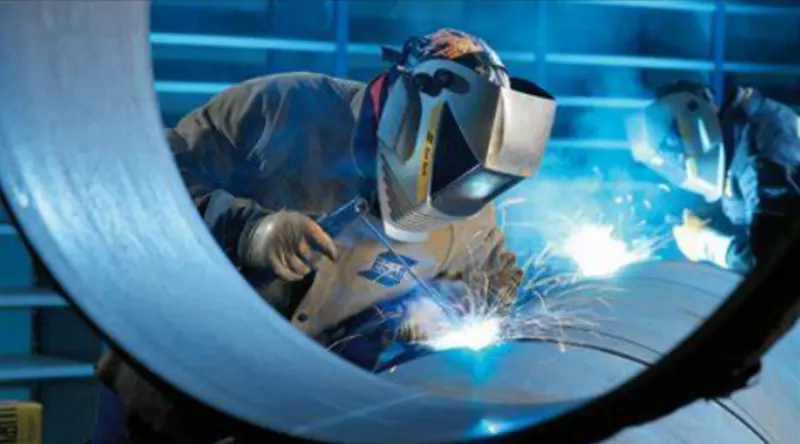
- Welding: using heat or pressure to fuse the parts together.
 Brazing and soldering: using a low melting point filler metal to bond the parts together.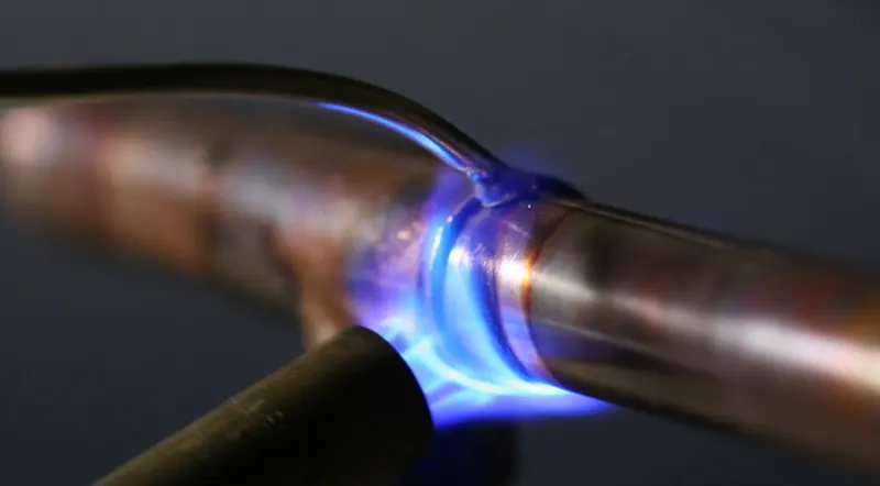
- Adhesive bonding: using a glue or resin to stick the parts together.
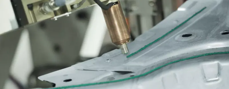
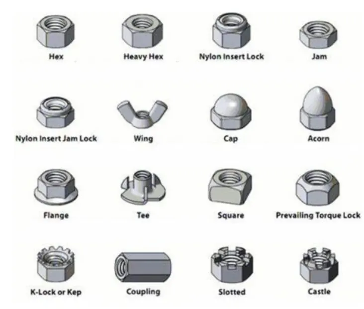
- Mechanical joining: using fasteners, clips, rivets, screws, etc. to attach the parts together.
Q3 What is Resistance Welding & its application in the automotive sector?
Answer:-
Resistance welding is a process that uses electric current to heat and join metal parts together. It is widely used in the automotive industry for various components such as car bodies, frames, wiring, fuel tanks, etc.
Resistance welding has many advantages such as low cost, high speed, adaptability to different materials and thicknesses, and robustness to fit-up variations However, it also faces some challenges such as weld quality variation, phase transformations, elemental segregation, solidification defects and cracking.
Application:
- Resistance welding is widely used in automotive industries.
- Projection welding is widely used in production of nuts and bolts.
- Seam welding is used to produce leak proof joints required in small tanks, boilers etc.
- Flash welding is used to welding pipes and tubes.
Advantages:
- It can weld thin (0.1 mm) as well as thick (20mm) metals.
- High welding speed.
- Easily automated.
- Both similar and dissimilar metals can be welded.
- The process is simple and fully automated so does not require high skilled labor.
- High production rate.
- It is an environmentally friendly process.
- It does not require any filler metal, flux and shielding glasses.
Disadvantages:
- High equipment cost.
- The thickness of the work piece is limited due to current requirements.
- It is less efficient for high conductive materials.
- High electric power required.
- Weld joints have low tensile and fatigue strength.
Q4 What is fusion welding & types of fusion welding with its application in the automotive sector?
Answer:-
Fusion welding is a process that uses heat to join or fuse two or more materials by heating them to a melting point. There are many types of fusion welding, such as arc welding, resistance welding, laser beam welding, etc. Fusion welding has applications in the automotive sector, such as manufacturing of cars and construction equipment Some of the advantages of fusion welding are high strength, speed, and versatility. Some of the disadvantages are distortion, residual stress, and loss of mechanical properties in the heat-affected zone.
Types of Fusion Welding Processes
After finding the full definition of fusion welding, it is crucial to understand fusion welding types. The different types of fusion welding are categorized based on the heat source. below are some of the main types of fusion welding:
Arc Welding
Fusion arc welding is the most common type of fusion welding. Arc welding involves connecting two or more parts using an electric art. The electric arcs produce high levels above 6000 degrees Fahrenheit using the machines like YES WELDER Digital MIG-205DS MIG welder. This feature makes fusion arc welding ideal for joining hard materials. Welders can also perform arc welding underwater. The most common types of arc welding include:
Shielded metal arc welding is used for welding ferrous and non-ferrous materials regardless of the position.
Tungsten inert gas welding uses non-consumable tungsten to create the arc between the electrode and the base plate. The TIG welders for aluminum use an inert shielding gas to prevent contamination and oxidation.
Metal gas arc welding involves the formation of an electric arc between the wire electrode and the material using the MIG welders. The use of shielding gas prevents contamination.
Submerged arc welding is the method that involves using flux and a consumable electrode. The flux prevents the sparks and spatters and conducts electricity while in the molten state.
Plasma arc welding involves the formation of an electric arc between the nozzle and the electrode. The electric arc ionizes the argon gas found in the chamber.
Flux cored arc welding is an alternative to shielded Metal Arc Welding. The whole process involves feeding consumable electrodes with flux using the flux core welders for the thickest metals.
Gas Welding
Some people would refer to it as Oxy-fuel or oxyacetylene welding. This process involves using a blowpipe held in the hand that combines both oxygen and acetylene gas to produce a flare. It is a solvent-based fusion welding that requires a flame to meltdown and connect the surface. Oxygen acts as the primary fuel source for the flame.
This welding type bases its foundation that there must be oxygen to produce fire. The oxygen allows it to create an extremely hot flame that surpasses 4500 degrees Fahrenheit.
High Energy Welding
High energy welding is a type of fusion welding that uses light radiation to produce heat. Welders blast the radiation on the material’s surface, turning them into a molten state. The two pieces will join once they cool down. The two types of high-energy fusion welding include:
Electron Beam Welding
This high-energy welding uses high-velocity electrons to join two different materials. The process takes place under normal atmospheric pressure, and the electrons produce heat in the material as they enter. The welts are mostly deep and narrow.
Laser Beam Welding
Laser beam welding utilizes a laser beam as the primary source of heat. The use of the laser beam helps maintain a highly focused energy source that is used to join different metal pieces of plastics. It uses light energy to produce heat. The rig produces dissipated light that warms the surface with every single blast.
Resistance Welding
Resistance welding is one of the fastest fusion welding types. The speed makes it best for use in the automotive industry. Two types of resistance welding include:
Resistance Seam Welding
This type of resistance welding involves creating a persistent joint with alternating nuggets. It uses shifting disks to replace the traditional spot welding electrodes as the process goes on.
Resistance Spot Welding
This form of bonding produces heat across two electrodes and depends on the material’s properties and thickness of the workpiece. Welders confine the voltage to a precise spot as the separate workpieces combine concurrently.
Friction Welding
Friction welding involves the joining of two different materials using mechanical friction. There are numerous procedures to perform mechanical friction on steel, aluminum, and wood. The process is arduous, but the heat produced is enough to soften and join two separate parts as they cool.
Some of the main types of friction welding include:
Rotary friction welding
Friction stir spot welding
Linear friction welding
Friction stir welding
During friction welding, one does not require shielding gas, filler, or flux. The process is best for joining light and non-weldable materials such as alloys for aluminum.
Applications of Fusion Welding
Several processes involve the use of fusion welding. Structural engineers use fusion welding when manufacturing large structures such as:
Airplanes
Bridges
Ships
Pressure vessels
Welded pipes
Shielding explosives
Since it produces high heat levels, one can use fusion metals to combine different materials regardless of their thickness. Some of the main applications include:
Joining Metals
Fusion welding involves using high heat levels in joining two or more separate parts. Unlike soldering, fusion welding melts the base metal and may require a filler material to make a joint. High heat exposure turns the metal part into a molten state. These parts join together to form a weld bead as it cools down. The result is always stronger than the base material.
When joining metals, one may need to exert pressure to make welds with a heat source. When joining two metals, shielding gas helps prevent the filler material or joint from contaminating or oxidizing.
Joining Plastics
Fusion welding is also applicable when joining plastics. Solvent welding uses adhesives instead of heat. Joining plastics using fusion welding takes place in 3 states which include;
Preparing the surfaces by cleaning and drying
Applying heat and exerting pressure on the molten part.
Cool down the molten parts to create a strong bond between the two plastics. The process might require a cooling room. However, this may not be important since the process is also fast.
Q5. What is the 3-2-1 principle?
Answer:-
3-2-1 principle used for jig and Fixture Locating Method
Principle Of Location in Jig And Fixture :-
The principle of location is being discussed here with the help of a most popular example which is available in any of the books covering jigs and fixtures. It is important that one should understand the problem first.
Any rectangular body may have three axes along x-axis, y-axis and z-axis. It can move along any of these axes or any of its movement can be released to these three axes. At the same time the body can also rotate about these axes too. So the total degree of freedom of the body along which it can move is six. For processing the body it is required to restrain all degrees of freedom (DOF) by arranging suitable locating points and then clamping it in a fixed and required position. The basic principle used to locate the points is desirable below.
[1] It is also known as a six-pin or six-point location principle. In this, the three adjacent locating surfaces of the blank (workpiece) are resting against 3, 2, and 1 pin respectively, which prevent 9 degrees of freedom.
[2] The remaining three degrees of freedom are arrested by three external forces usually provided directly by clamping.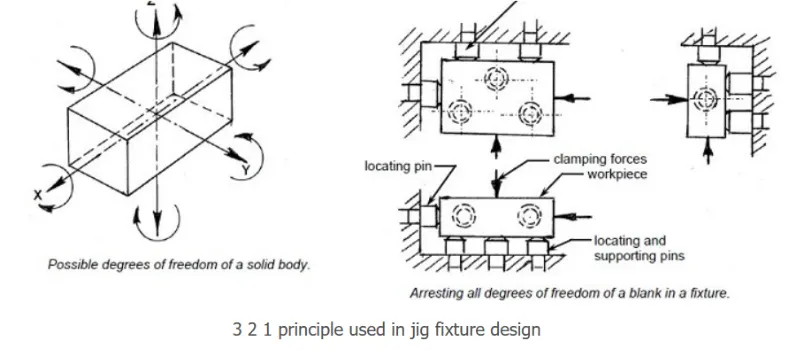
3-2-1 Principle Statement :
The 3-2-1 principle states that the six locators are sufficient to restrict the required degree of freedom of any workpiece. In this, motion is restricted using clamps and locators. A three-pin base can restrict five motions and six pins restrict nine motions.
Methodology of 3-2-1 Principle:
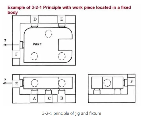
For this, refer the below figure;
[1] The workpiece is resting on three pins A, B, and C which are inserted in the base of the fixed body.
[2] The workpiece cannot rotate about the axes XX and YY and also cannot move downward.
[3] In this way, the five degrees of freedom 1,2,3,4 and 5 have been arrested.
[4] Two pins D and E are inserted in the fixed body, in a plane perpendicular to the plane containing pins A, B & C.
[5] Now the workpiece cannot rotate about the Z-axis and also it cannot move towards the left.
[6] Hence the addition of pins D and E restrict three more degrees of freedom, namely 6, 7, and 8.
[7] Another pin F in the second vertical face of the fixed body, arrests degree of freedom 9.
The above method of locating a workpiece in a fixture is called the 3-2-1 Principle.
Summary of 3-2-1 Principle:
A workpiece will be completely confined when blanked against:
- 3 points in one plane: The “3” in 3-2-1 refers to 3 locators (passive fixture elements) on the primary locating/datum surface.
- 2 points in another plane: The “2” in 3-2-1 refers to 2 locators on the secondary locating/datum surface.
- 1 point in a third plane: The “1” in 3-2-1 refers to 1 locator on the tertiary locating/datum surface
Some basic principles or rules need to be followed while planning for locating blanks in fixtures, such as;
- One or more surfaces (preferably machined) and/or drilled/bored hole(s) are to be taken for reference
- The reference surfaces should be a significant and important feature(s) based on which most of the dimensions are laid down
- Locating should be easy, quick and accurate In case of locating by pin, the pins and their mounting and contact points should be strong, rigid and hard
- A minimum of three-point must be used to locate a horizontal flat surface
- The locating pins should be as far apart as feasible
- Vee blocks and cones should be used for self-locating solid and hollow cylindrical jobs.
Types Of Locators used In Jig And Fixture For supporting :
The location arrangement depends on the type of operation, degrees of required accuracy.
- Flat locators: These are used for the location of the flat machined surfaces of a component.
- Cylindrical locators: These are used for the location of components with drilled holes.
- Conical locators: These locators are used to support the workpieces with cylindrical holes.
- Jack pin locators: These locators support rough workpieces.
- Drill bush locators: These locators hold and locate the cylindrical workpieces.
- Vee locators: These locators hold circular and semicircular workpieces.
Q6. Define Body coordinate system?
Answer:-In geometry, a coordinate system is a system that uses one or more numbers, or coordinates, to uniquely determine the position of the points or other geometric elements on a manifold such as Euclidean space.The order of the coordinates is significant, and they are sometimes identified by their position in an ordered tuple and sometimes by a letter, as in "the x-coordinate". The coordinates are taken to be real numbers in elementary mathematics, but may be complex numbers or elements of a more abstract system such as a commutative ring. The use of a coordinate system allows problems in geometry to be translated into problems about numbers and vice versa; this is the basis of analytic geometry
Common coordinate system
Number line
Main article: Number line
The simplest example of a coordinate system is the identification of points on a line with real numbers using the number line. In this system, an arbitrary point O (the origin) is chosen on a given line. The coordinate of a point P is defined as the signed distance from O to P, where the signed distance is the distance taken as positive or negative depending on which side of the line P lies. Each point is given a unique coordinate and each real number is the coordinate of a unique point.

Cartesian coordinate system:-
Main article: Cartesian coordinate system
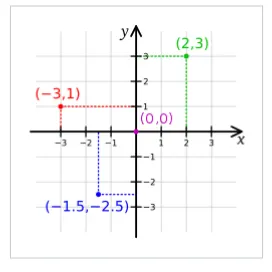
The Cartesian coordinate system in the plane.
The prototypical example of a coordinate system is the Cartesian coordinate system. In the plane, two perpendicular lines are chosen and the coordinates of a point are taken to be the signed distances to the lines.
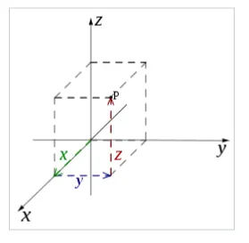
In three dimensions, three mutually orthogonal planes are chosen and the three coordinates of a point are the signed distances to each of the planes.[5] This can be generalized to create n coordinates for any point in n-dimensional Euclidean space.
Depending on the direction and order of the coordinate axes, the three-dimensional system may be a right-handed or a left-handed system. This is one of many coordinate systems.
Polar coordinate system
Main article: Polar coordinate system
Another common coordinate system for the plane is the polar coordinate system. A point is chosen as the pole and a ray from this point is taken as the polar axis. For a given angle θ, there is a single line through the pole whose angle with the polar axis is θ (measured counterclockwise from the axis to the line). Then there is a unique point on this line whose signed distance from the origin is r for given number r. For a given pair of coordinates (r, θ) there is a single point, but any point is represented by many pairs of coordinates. For example, (r, θ), (r, θ+2π) and (−r, θ+π) are all polar coordinates for the same point. The pole is represented by (0, θ) for any value of θ.
Cylindrical and spherical coordinate systems:-
Main articles: Cylindrical coordinate system and Spherical coordinate system
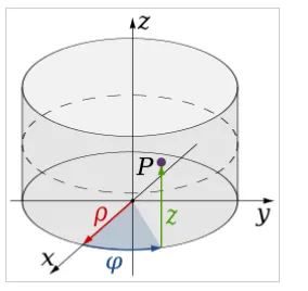
Cylindrical coordinate system
There are two common methods for extending the polar coordinate system to three dimensions. In the cylindrical coordinate system, a z-coordinate with the same meaning as in Cartesian coordinates is added to the r and θ polar coordinates giving a triple (r, θ, z). Spherical coordinates take this a step further by converting the pair of cylindrical coordinates (r, z) to polar coordinates (ρ, φ) giving a triple (ρ, θ, φ).
Homogeneous coordinate system
Main article: Homogeneous coordinates
A point in the plane may be represented in homogeneous coordinates by a triple (x, y, z) where x/z and y/z are the Cartesian coordinates of the point.[9] This introduces an "extra" coordinate since only two are needed to specify a point on the plane, but this system is useful in that it represents any point on the projective plane without the use of infinity. In general, a homogeneous coordinate system is one where only the ratios of the coordinates are significant and not the actual values.
Other commonly used systems:-
Some other common coordinate systems are the following:
- Curvilinear coordinates are a generalization of coordinate systems generally; the system is based on the intersection of curves.
- Orthogonal coordinates: coordinate surfaces meet at right angles
- Skew coordinates: coordinate surfaces are not orthogonal
- The log-polar coordinate system represents a point in the plane by the logarithm of the distance from the origin and an angle measured from a reference line intersecting the origin.
- Plücker coordinates are a way of representing lines in 3D Euclidean space using a six-tuple of numbers as homogeneous coordinates.
- Generalized coordinates are used in the Lagrangian treatment of mechanics.
- Canonical coordinates are used in the Hamiltonian treatment of mechanics.
- Barycentric coordinate system as used for ternary plots and more generally in the analysis of triangles.
- Trilinear coordinates are used in the context of triangles.
There are ways of describing curves without coordinates, using intrinsic equations that use invariant quantities such as curvature and arc length. These include:
- The Whewell equation relates arc length and the tangential angle.
- The Cesàro equation relates arc length and curvature.
Coordinates of geometric objects
Coordinate systems are often used to specify the position of a point, but they may also be used to specify the position of more complex figures such as lines, planes, circles or spheres. For example, Plücker coordinates are used to determine the position of a line in space.When there is a need, the type of figure being described is used to distinguish the type of coordinate system, for example the term line coordinates is used for any coordinate system that specifies the position of a line.
It may occur that systems of coordinates for two different sets of geometric figures are equivalent in terms of their analysis. An example of this is the systems of homogeneous coordinates for points and lines in the projective plane. The two systems in a case like this are said to be dualistic. Dualistic systems have the property that results from one system can be carried over to the other since these results are only different interpretations of the same analytical result; this is known as the principle of duality.
Transformations:-
There are often many different possible coordinate systems for describing geometrical figures. The relationship between different systems is described by coordinate transformations, which give formulas for the coordinates in one system in terms of the coordinates in another system. For example, in the plane, if Cartesian coordinates (x, y) and polar coordinates (r, θ) have the same origin, and the polar axis is the positive x axis, then the coordinate transformation from polar to Cartesian coordinates is given by x = r cosθ and y = r sinθ.
With every bijection from the space to itself two coordinate transformations can be associated:
- Such that the new coordinates of the image of each point are the same as the old coordinates of the original point (the formulas for the mapping are the inverse of those for the coordinate transformation)
- Such that the old coordinates of the image of each point are the same as the new coordinates of the original point (the formulas for the mapping are the same as those for the coordinate transformation)
For example, in 1D, if the mapping is a translation of 3 to the right, the first moves the origin from 0 to 3, so that the coordinate of each point becomes 3 less, while the second moves the origin from 0 to −3, so that the coordinate of each point becomes 3 more.
Coordinate lines/curves and planes/surfaces[edit]
"Coordinate line" redirects here. Not to be confused with Line coordinates.
"Coordinate plane" redirects here. Not to be confused with Plane coordinates.
In two dimensions, if one of the coordinates in a point coordinate system is held constant and the other coordinate is allowed to vary, then the resulting curve is called a coordinate curve. If the coordinate curves are, in fact, straight lines, they may be called coordinate lines. In Cartesian coordinate systems, coordinate lines are mutually orthogonal, and are known as coordinate axes. For other coordinate systems the coordinate curves may be general curves. For example, the coordinate curves in polar coordinates obtained by holding r constant are the circles with center at the origin. A coordinate system for which some coordinate curves are not lines is called a curvilinear coordinate system.[12] This procedure does not always make sense, for example there are no coordinate curves in a homogeneous coordinate system.
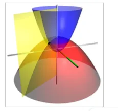
Coordinate surfaces of the three-dimensional paraboloidal coordinates.
In three-dimensional space, if one coordinate is held constant and the other two are allowed to vary, then the resulting surface is called a coordinate surface. For example, the coordinate surfaces obtained by holding ρ constant in the spherical coordinate system are the spheres with center at the origin. In three-dimensional space the intersection of two coordinate surfaces is a coordinate curve. In the Cartesian coordinate system we may speak of coordinate planes.
Similarly, coordinate hypersurfaces are the (n − 1)-dimensional spaces resulting from fixing a single coordinate of an n-dimensional coordinate system.[13]
Coordinate maps
The concept of a coordinate map, or coordinate chart is central to the theory of manifolds. A coordinate map is essentially a coordinate system for a subset of a given space with the property that each point has exactly one set of coordinates. More precisely, a coordinate map is a homeomorphism from an open subset of a space X to an open subset of Rn.It is often not possible to provide one consistent coordinate system for an entire space. In this case, a collection of coordinate maps are put together to form an atlas covering the space. A space equipped with such an atlas is called a manifold and additional structure can be defined on a manifold if the structure is consistent where the coordinate maps overlap. For example, a differentiable manifold is a manifold where the change of coordinates from one coordinate map to another is always a differentiable function.
Orientation-based coordinates
In geometry and kinematics, coordinate systems are used to describe the (linear) position of points and the angular position of axes, planes, and rigid bodiesIn the latter case, the orientation of a second (typically referred to as "local") coordinate system, fixed to the node, is defined based on the first (typically referred to as "global" or "world" coordinate system). For instance, the orientation of a rigid body can be represented by an orientation matrix, which includes, in its three columns, the Cartesian coordinates of three points. These points are used to define the orientation of the axes of the local system; they are the tips of three unit vectors aligned with those axes.
Geographic systems
The Earth as a whole is one of the most common geometric spaces requiring the precise measurement of location, and thus coordinate systems. Starting with the Greeks of the Hellenistic period, a variety of coordinate systems have been developed based on the types above, including:
- Geographic coordinate system, the spherical coordinates of latitude and longitude
- Projected coordinate systems, including thousands of cartesian coordinate systems, each based on a map projection to create a planar surface of the world or a region.
- Geocentric coordinate system, a three-dimensional cartesian coordinate system that models the earth as an object, and is most commonly used for modeling the orbits of satellites, including the Global Positioning System and other satellite navigation systems.
Q.7 Elaborate Body plane system & its essentials.
Answer:-
Body planes are imaginary lines that divide the body into different sections or portions. They are used to describe the location and direction of body structures. There are three main types of body planes:
- Sagittal plane: divides the body into left and right sides.
- Coronal plane: divides the body into front and back parts.
- Transverse plane: divides the body into upper and lower halves.
The essentials of the body plane system are:
- The body must be in the anatomical position, which means standing upright, facing forward, arms at the sides, palms facing forward, and feet parallel.
- The body planes must be perpendicular to each other and to the three axes (X, Y, and Z) of the coordinate system.
- The body planes must be named according to the direction of the cut and the section of the body they reveal.