Week 2:- BiW Fixture Basics Challenge
1. What is the process of project execution activity?
It is a general activity which is involved in BIW fixture and tooling. It is a starting phase of every project. It starts with basic requirements,We received from the customer.
There are various steps involved in project activities.
1. RFQ
Request for quote (RFQ) is a process wherein an enterprise asks a set of potential suppliers or service providers to submit their price quotations and stand a chance to supply or provide goods or services.
2. First Specification Discussion meeting
After RFQ received,Technical offer,commercial offer,a timeline of the project etc.,Will be discussed and prepared from outside.
3. Offer submission
After the finalization in the meeting,The offer will be submitted to the customer end. Customer will arrange to get an offer from other suppliers too. Based on the technical, Cost, Quality, Standard and name in the industries, The customer will be finalizing the offer.
4. LOI/PO receipt
After an offer has been finalized customer will be releasing the LOI/PO (purchase Order). After getting PO from the customer,We have to prepare the schedule.
5. Schedule preparation
Schedule preparation is nothing but dividing the different activities like kick offmeeting, Design data study, DAP,Simulate quality check, 2D detailing, Drawing check, release of BOM, Manufacturing, Bought outs of electrical and mechanical components, assembly of the fixture, installation and commissioning at cutomer end etc., These activities will be traced in the schedule preparation chart.
6. BOM Preparation
A bill of materials (BOM) is a comprehensive inventory of the raw materials, assemblies, subassemblies, parts and components, as well as the quantities of each needed to manufacture a product. In a nutshell, it is the complete list of all the items that are required to build a product.
7. Design concept preparation
In design concept preparation,The design of the layout is been prepared at a very initial level which gives the information of placements of robots and fixtures.
8. Customer approval
After design concepts,The customer will review the design concepts. If the design need to be made simple or some other correction needs to be done in concept design will be discussed and after meeting the requirements of the customer, They will give approval to the design to go on with further activities.
9. Detailing & Drawing release
Once the customer approved the process,The detailing of the fixture parts which is to be manufactured has been done with giving appropriate dimension and GD & T symbols. All the dimensions which are the necessity for manufacturing should be included with GD&T in the draqing before releasing the drawing to the manufacturing team.
10. Manufacturing / BOP ordering
The mechanical and electrical parts like sensors,Cylinders etc.,Which needs for a fixture are ordered as per design specification.
11. Mechanical / Electrical Assembly
After the materials ordered received to our end.The quality will check the working conditions and technical specs. Which meets our reqirements. After the quality check,The mechanical and the electrical parts are assembled as per design.
12. Quality inspection
In Quality inspection, we have to check all dimensions,positional accutancy,Coordinates are checked using CMM.
13. Internal trial & testing
After QC check internal trials are made to check the operation of the fixture. It is a first trial taken inhouse,So we will see by putting the assembly in the fixture whether the seating of assembly/panel suited correctly,Whether the clamping operation is done properly,Also whether the pins are getting into the holes etc.,
14. Online trial
The trail will be done in automatically made through the control panel. The process sequence of operation is checked as by the designed way.
15. Packaging
After approval of QC,Packaging is been done as per standards.Certain companies follow certain packaging standards,So the packaging should be one as per customer standards.
16. Dispatch
After the fixture has been packed for delivery as per standards. Its been despatched to the customer.
17. Installation as per layout
According to the design the installation and commissioning team will install the fixtures.
18. Trial & training at Customer
So in customer trail,we have to achieve the confirmed quantity of assemblies. Once it is achieved,Training will be given to the operator,staffs,engineers who involved in this process. The sequence of the working process by the fixture will be explaned in detail. The checkpoints which have to be done after placing the panels into the fixture will be made clear to them.
19. Buyoff meeting
n this meeting customer will give reviews about the fixtures,Sometimes a customer may need/feels better to do some additional work also,It will be discussed and finalize in the meeting.
20. Final handover
The fixture and the documents suopport the fixtures/Production will be handed over. Documents like clamps validation document,Ergo sheets,BOMs,Charts will be delivered abd handed over to customers.
2.What are the types of joining processes?
Joining includes welding, brazing, soldering, adhesive bonding of materials. They produce permanent joint between the parts to be assembled. They cannot be separated easily by application of forces. They are mainly used to assemble many parts to make a system.
Types of Joining process:
- Welding - A permanent joining process does not allow easy dismantling of jointed parts without rupturing them
- Soldering - process used for joining metal parts to form a mechanical or electrical bond.
- Brazing - process for joining two pieces of metal that involves the application of heat and the addition of a filler metal
- Fasteners (including nut-bolt, nail, hook, clip, clutch, button, zipper, etc.) - a device that attaches one thing to another or holds something in place,
- Adhesive bonding - the process of joining two surfaces together, usually with the creation of a smooth bond.
- Resin bonding - the process of scattering loose dried aggregates onto a coating of resin after the resin has been applied to a surface.
- Cotter joint - a method of temporarily joining two coaxial rods
- Knuckle joint - a mechanical joint that connects two rods or bars at an angle, allowing limited angular movement
3. What is Resistance Welding & its application in the automotive sector?
Resistance welding
Resistance welding (RW) is a fusion welding processes that uses a combined effect of heat and pressure to accomplish joining. This heat is generated by electrical resistance to current flow at the location to be welded. Weld nugget is generated by this process. RW uses no shielding gases, flux, or filler metal. Electrodes that conduct electrical power to the process are non-consumable.
1.Resistance spot welding
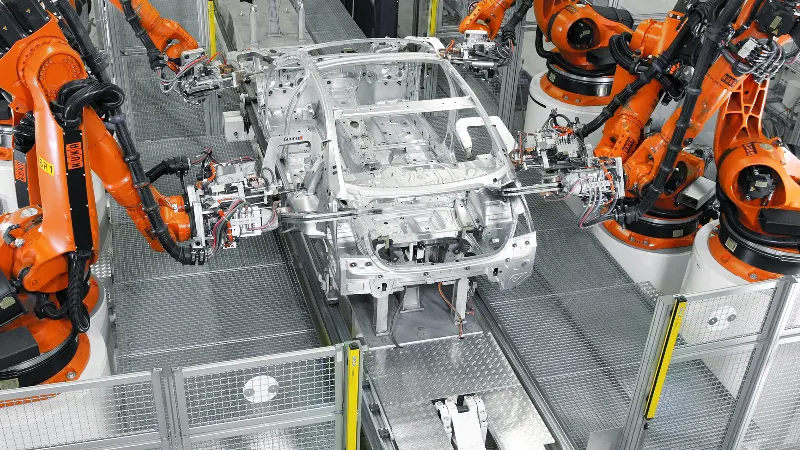
Resistance spot welding (RSW) or simply spot welding is widely employed in automotive and aeronautical industries. This type of welding employs a tremendous amount of current and a very low voltage. Numerous types of metals like different grades of steels, aluminum (Al), magnesium (Mg), titanium (Ti), copper (Cu), and their alloys. Generally, thin sheets of similar or dissimilar metals are joined by RSW in lap joint configuration. RSW also suffers from a few limitations like liquation cracking, voids, misalignment, electrode wear, etc. Thicker sheets of metals are generally difficult to weld by RSW because the heat flows into the surrounding metal very easily.
Advantages of Resistance Spot Welding
- Comparatively Low cost.
- Resistance Spot Welding (RSW) method doesn\'t need highly skilled worker.
- Distortion or warping of parts is eliminated though it leaves some depressions or indentation.
- The joint made is highly uniform.
- Automatic or semi-automatic operation both can be done.
- There is no need for edge preparation.
- Welding can be done in quick succession. It just needs a few seconds to make the joint.
2.Resistance seam welding
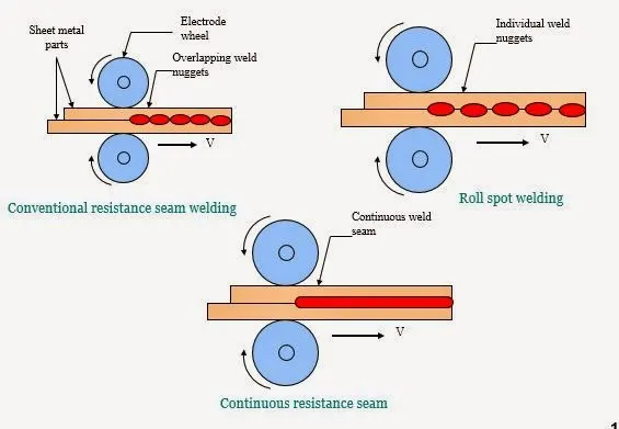
In this type of resistance welding, the joint is produced progressively along the length of the weld. This gives a continuous and leak tight joint in sheet metals. The weld may be made with overlapping or continuous work pieces. In automobile industries, this welding process is used to produce leak proof fuel tanks. This process provides high welding speeds, but its applicability is limited by component shape and wheel access. A seam welding process in operation.
Advantages of Resistance Seam Welding
- Airtight welds: One of the most important characteristics of a continuous weld is that it can create airtight and watertight seals. This is very important in creating metal structures that need air or water leakage protection, like air or liquid-tight vessels.
- Fast weld process: Weld is possible at high speeds. And, since the whole process is automatic, resistance seam welding is faster than other alternatives like spot welding
- No filler/flux required: The weld is possible without using any filler or flux material.
3. Resistance projection welding
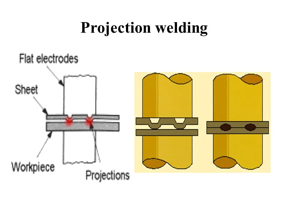
Resistance projection welding can be found in the automotive industry, where screw-fastener parts such as nuts and studs (see above) are joined to metal sheet components. It is also found in cross wire and bar welding, or in day to day products such as shopping carts. As with resistance spot welding, the difficulties in welding aluminum, high strength steels and coated steels has encouraged Huys to look for simple solutions.
Advantages of Resistance Projection Welding
- Simultaneous operation can be done i.e. more than one welds can be made.
- Projection welding has this advantage that it can weld metals of thickness which is not suitable for spot welding.
- Projection welding electrodes have a longer life when compared to spot welding electrodes. Its because projection welding electrodes have to withstand less wear and less heating.
- Resistance projection welding is not limited to sheet to sheet joints.
- Projection welding can be done in specific points which are desired to be welded.
- In difficult welding work projection welding gives a better heat balance.
- Projection welding saves electricity because it needs less current to produce heat. So it reduces the shrinkage and distortion defects.
Resistance welding application in the automotive sector are
The automotive application of permanent joining methods is discussed with illustrative diagrams. The resistance welding techniques namely spot and seam welding are presented with specific applications. The solid state welding method viz. the friction welding is also discussed. The need for innovative and cost effective welding methodologies to meet the growing requirement of lighter and fuel efficient vehicles is highlighted. The technological advancement in the metal joining in the context of auto industry is presented. The working aspect of medium frequency welding is briefed with its distinct merits. The magnetic pulse welding-a breakthrough in metal joining technique is also explained. The following points concluded from this above study.
- The automotive manufacturers focused on producing lighter yet strong and fuel efficient vehicles using new improved alternative materials. This necessitated most efficient welding techniques that produce lighter weld joints without adding additional material.
- The commercial implementation of magnetic pulse welding can prove advantageous for automotive industries to manufacture lighter and fuel efficient cars.
- The advancement in resistance spot welding and seam welding allows evolving new geometries for automobile transmissions and undercarriage systems using new combinations of materials, particularly made from powder metallurgy process.
4. What is fusion welding & types of fusion welding with its application in the automotive sector?
Fusion welding
Fusion welding is a process that uses heat to join or fuse two or more materials by heating them to melting point. The process may or may not require the use a filler material.
- Gas welding
- Arc welding
- Shielded Metal Arc Welding (SMAW)
- Gas–Tungsten Arc Welding (GTAW)
- Gas–Metal Arc Welding (GMAW)
- Plasma Arc Welding (PAW)
- Submerged Arc Welding (SAW)
GAS WELDING
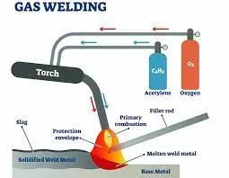
Gas welding is a welding process thatmelts andjoints metals by heating themwith a flame caused by a reaction of fuelgas and oxygen.The mostcommonly used method isOxyacetylene welding,due to its highflame temperature.
Arc welding
Arc welding is a type of fusion welding that uses a welding power supply to create an electric arc between an electrode and the base material to melt the metals at the welding point. They can use either direct (DC) or alternating (AC) current, and consumable or non-consumable electrodes. Arc welding processes may be manual, semi-automatic, or fully automated
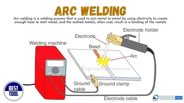
Shielded Metal Arc Welding (SMAW)
Shielded metal arc welding (SMAW) is a welding process in which coalescence of metals is produced by heat from an electric arc maintained between the tip of a consumable electrode and the surface of the base material in the joint being welded.
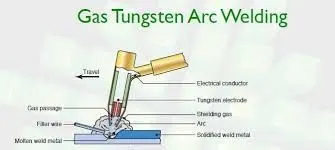
Gas–Tungsten Arc Welding (GTAW)
Fusion welding application in the automotive sector are
The automotive application of permanent joining methods is discussed with illustrative diagrams. The resistance welding techniques namely spot and seam welding are presented with specific applications. The solid state welding method viz. the friction welding is also discussed. The need for innovative and cost effective welding methodologies to meet the growing requirement of lighter and fuel efficient vehicles is highlighted. The technological advancement in the metal joining in the context of auto industry is presented. The working aspect of medium frequency welding is briefed with its distinct merits. The magnetic pulse welding-a breakthrough in metal joining technique is also explained. The following points concluded from this above study.
- The automotive manufacturers focused on producing lighter yet strong and fuel efficient vehicles using new improved alternative materials. This necessitated most efficient welding techniques that produce lighter weld joints without adding additional material.
- The commercial implementation of magnetic pulse welding can prove advantageous for automotive industries to manufacture lighter and fuel efficient cars.
- The advancement in resistance spot welding and seam welding allows evolving new geometries for automobile transmissions and undercarriage systems using new combinations of materials, particularly made from powder metallurgy process.
5. What is the 3-2-1 principle?
A widely used method of accomplishing these two objectives uses the 3-2-1 principle, so-called because it entails three steps that employ three, then two, then one fixed points of known location. Since that adds up to six fixed points, it's also known as the six point method.
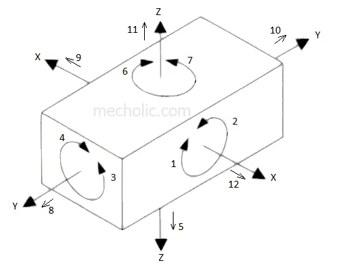
3-2-1 Principle of Location used in Jig & Fixtures:
[1] It is also known as a six-pin or six-point location principle. In this, the three adjacent locating surfaces of the blank (workpiece) are resting against 3, 2, and 1 pin respectively, which prevent 9 degrees of freedom.
[2] The rest three degrees of freedom are arrested by three external forces usually provided directly by clamping.
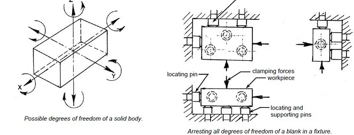
3-2-1 Principle Statement :
The 3-2-1 principle states that the six locators are sufficient to restrict the required degree of freedom of any workpiece. In this, motion is restricted using clamps and locators. A three-pin base can restrict five motions and six pins restrict nine motions.
Methodology of 3-2-1 Principle:
For this, refer the below figure;
[1] The workpiece is resting on three pins A, B, and C which are inserted in the base of the fixed body.
[2] The workpiece cannot rotate about the axes XX and YY and also cannot move downward.
[3] In this way, the five degrees of freedom 1,2,3,4 and 5 have been arrested.
[4] Two pins D and E are inserted in the fixed body, in a plane perpendicular to the plane containing pins A, B & C.
[5] Now the workpiece cannot rotate about the Z-axis and also it cannot move towards the left.
[6] Hence the addition of pins D and E restrict three more degrees of freedom, namely 6, 7, and 8.
[7] Another pin F in the second vertical face of the fixed body, arrests degree of freedom 9.
The above method of locating a workpiece in a fixture is called the 3-2-1 Principle.

Summary of 3-2-1 Principle:
A workpiece will be completely confined when blanked against:
- 3 points in one plane: The “3” in 3-2-1 refers to 3 locators (passive fixture elements) on the primary locating/datum surface.
- 2 points in another plane: The “2” in 3-2-1 refers to 2 locators on the secondary locating/datum surface.
- 1 point in a third plane: The “1” in 3-2-1 refers to 1 locator on the tertiary locating/datum surface
6. Define Body coordinate system?
Body coordinate system in BIW
The body coordinate system has been widely used in the automotive industry for drawing of body parts,Products and process design.
A coordinate system is a reference system consisting of a set of points,lines and surfaces,used to define the positions of points in space in either two or three dimensions.
In general BCS is also called as car line and body line.
X=Longitudinal direction [(Fore and After - F/A) or (Front O Line - FOL)]
Y=Transverse direction [(Cross car - C/C) or (Center O Line - COL)]
Z= Vertical Direction [(Up and Down - U/D) or (Bottom O Line - BOL)]
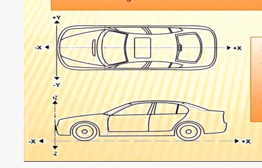
- The origin of the body coordinate system (OX) is defined at the front center of a vehicle,It indicates a length of car and the coordinate system (OZ) is below its underbody indicates height of car,and the coordinate system (OY) its starting point is the center of car body indicates width of car.
- The above schematic figure shows the basic car geometry system used widely to specify the position of parts which is to be assembled to the car body. From the first part of the production line this coordinate system is used to specify its position. According to the CAD data some references are specified to the car body on the basis of which each and every part of the car body is assembled respectively.
- The fixture position is also defined with reference of these coordinate system. The fixture is installed on the basis of these reference point defined by CAD data according to which the fixture base plate and the accessories are installed. Each and every parts measurement is done with reference to this coordinate system. The deviation in the assembly of car body and the components is shown with respect to these coordinates. An individual part measurement is also done with respect to these coordinate system. Accuracy of the BIW is also defined by the final measurement report which are based on these coordinate system.
7. Elaborate Body plane system & its essentials.
Body planes are the reference planes in an automotive car.These planes are used to desfine the GD&T of all car parts in a automotive domain.
Body planes are 3 mutually perpendicular.Imaginary planes.These are genrally considered to be present at the driver position or sometimes at the engine location or at the front end of the car,depending on the customer.
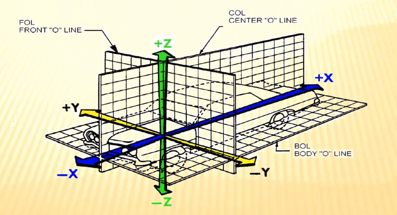
The measurement from the body planes to the parts are called as bodyline dimensions
These body planes are called as
FOL Front O Line
COL Centre O Line
BOL Body O Line
The measurement along FOL or X axis is called as F/A Front Aft
The measurement along COL or Y axis is called as C/C Cross Car
The measurement along BOL or Z axis is called as U/DUP Down
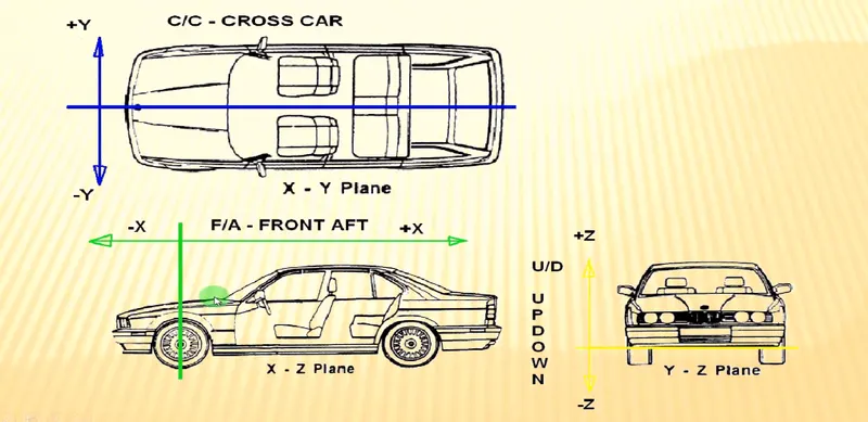
Bodyline dimension are essential for the reasons stated below,
- It defines the exact position of each product in the vehicle w.r.t a fixed origin.
- It ensures flawless design for assembly.
- While designing lines,All the designs are carried out relative to the bodyline,Fixtures,Turn tables etc.,
- It assists in easy location of different parts in a vehicle.
- It aims in creating a standardized system.
- It assists in quality checks.