Week 2:- BiW Fixture Basics Challenge
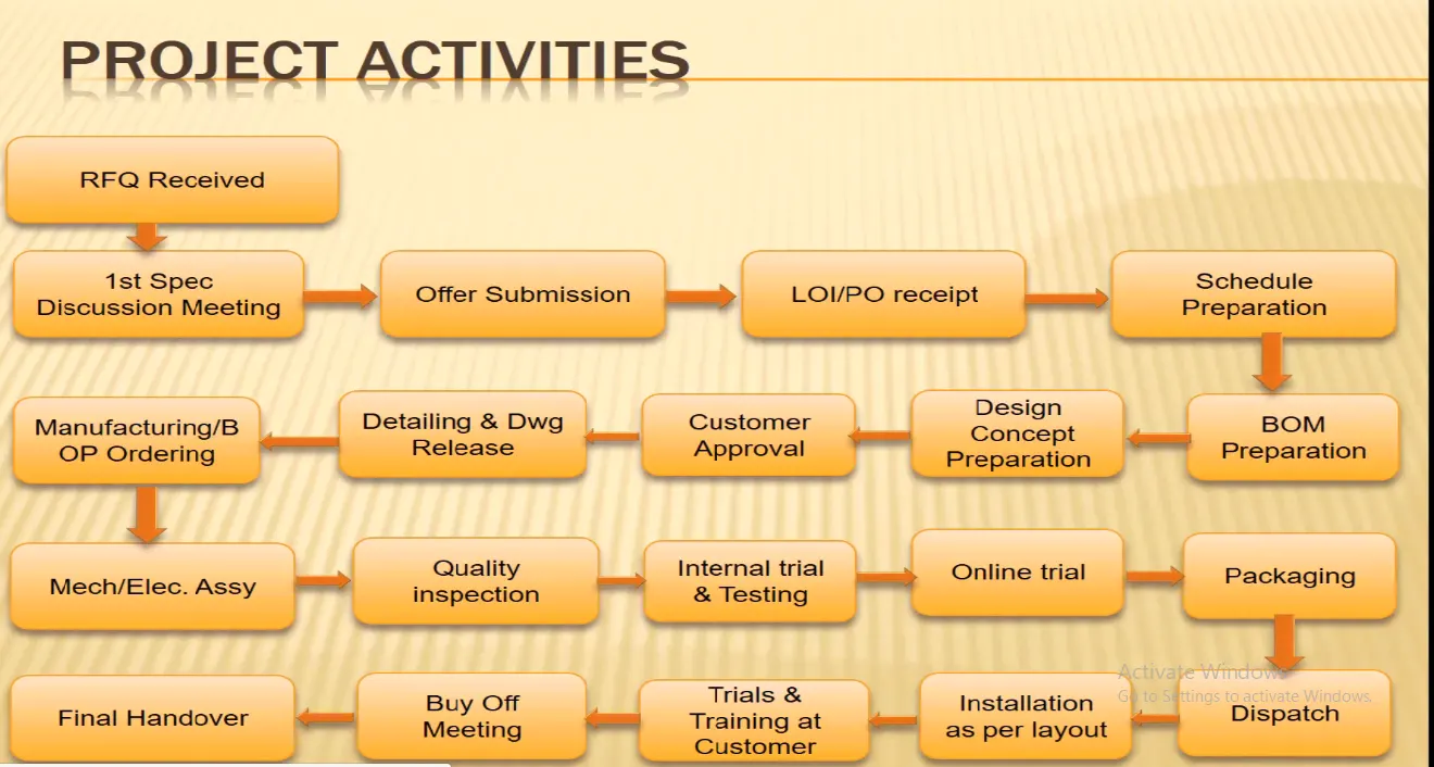
1.Process Of Project Excecution Activity
RFQ Recived --> First spec Discussion Meeting --> Offer Submission --> Po recipt --> Schedule Preparation --> BOM Preparation --> Design Cocept Preparation --> Cutomer Approval-->Detailing & DWG Release --> BOP Ordering --> Manufacturing --> Mech/Electical Assembly --> Quality Inspection --> Internal & Trial Testing --> Online Trail --> Packaging --> Dispatch --> Installation asper layout --> Trial & Training at customer --> Buy off Meeting --> Final Handover
RFQ
- Request for Quotation shortly known as RFQ is received from the customer end.
- It has all the requirements of the customer as per which the manufacturing has to be performed.
- It consists of the technical asspects, commercial aspects, project completion time.
First Spec Discussion Meeting
- Once the RFQ is received, a discussion will be carried out regading the customer inputs.
- Feasibility of the project, completion time, technical aspect will discussed.
- Based on the technical aspects a commercial offer will be finalized.
Offer Submission
- Once the discussion over all the aspects discussed are summarized.
- These aspects are finally offered to the customer end.
- Customer will get offers from various other sources as well.
- Based on the comparison, an optimum offer will be finalized.
LOI/PO receipt
- Once the offer is finalized , the customer will release the LOI/PO which is the purchase order.
- This is an indication for the process to start from the manufacturer end.
Schedule Preparation
- Once the LOI/PO is received, scheduling starts.
- Scheduling defines how this project is going to be processed further.
- It provides a proper sequence in which the activities are to be followed to achieve maximum output.
- This schedule must be able to match paramaters which was offered to the customer durint offer submission.
BOM Preparation
- Billi of Material is prepared once the scheduling is done.
- A BOM is a structured, comprehensive list of the materials, components and parts required to manufacture or repair a product, as well as the quantities in which the materials are needed and their names, descriptions and costs.
- A BOM also includes instructions for procuring and using these materials.
Design Concept Preparation
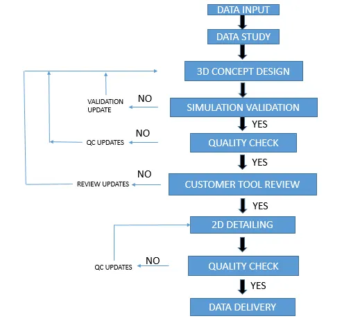
- Here the Data is first received as input from the customer in form of 3D data or 2D drawings.
- These data will be studied initially inorder to proceed further.
- After examining it properly, the design concepts are further created to meet the customer requirements.
Customer Approval
- The created design concepts will be sent to the customer to review them.
- The customer checks if it is in line with all the technical aspects which was proposed earlier.
- If any changes requried will be made.
- Once the customer is satisfied with the results the process will be carried on further.
Detailing and Drawing Release
- Once all the necessary changes are made, a detailed drawing is made fromm the manufacturer end using GD & T.
- GD&T is an acronym that stands for Geometric Dimensioning and Tolerancing. It is a symbolic language used by designers to communicate manufacturing constraints and tolerances clearly.
Manufacturing/BOP ordering
- The Mechanical and Electrical parts which are required for the manufacturing process of the component will be ordered.
Mechanical / Electrical Assembly
- After receiving all the required parts, the parts will be initially checked for quality.
- Upon clearing the quality check, these parts will be assembled to produce the final component.
Quality Inspection
- Once the assembly is done, another Quality check is done on the finished component.
- The dimensions, roughness, tolerances and accuracy are checked.
Internal Trial testing
- After the Quality check is done, internal trials are performed with the component.
- These trials are performed inorder to check for theproper functioning of the component.
Online Trial
- Online trial is performed automatically through control pannel.
- It also checks the feasibility of the assembly in an automated way.
- It is sent to the customer for approval.
Packaging
- Once the customer approves the assembly, a component is sent to the customer for trial.
- This packaging is done as per the packaging standars followed in industries.
Dispatch
- Once proper packaging is done, it is dispatched to the customer.
Installation as per layout
- An initial installation will be done as per the layout.
- This ensures the mounting position of the component.
- This layout is done as per the customr requirements.
Trials and Training at customer
- After the installation , trials will be performed at the customer end.
- These trials are to ensure that the number of components are produced as stated in the offer submission.
- The quality of the components are also checked to make sure they are up to the standards as proposed.
Buy off meeting
- This is the pen ultimate stage of this project activity which occurs after the trial and training at customer end.
- All the components are reviewed by the customer, any necessary changes are made.
Final Handover
- Once all the reviews are over, if the customer is satisfied then the product will be handed over to the customer
- This marks the end of the Project Execution Activity.
2.Types of Joining Process
Joining consists of a large number of processes used to assemble two or more parts together, irrespective of their composition, properties, features, shapes, etc.
By definition, joining is one of the manufacturing processes by which two or more materials can be permanently or temporarily joined or assembled together with or without the application of external element in order to form a single unit
Types of Joining
Joining processes are typically divided into three categories
- Mechanical joining
- Welding
- Chemical joining
Mechanical Joining
- Mechanical joining – also called joining by forming – has become interesting for the automotive industry due to the request to reduce fuel consumption and thereby emissions.
- In order to reduce weight on the car body, the usage of lightweight materials in the body-in-white application has increased.
- This includes aluminium, high-strength steel alloys, polymers, and composites.
- Here the different type of mechanical joining becomes important.
- All mechanical joining methods are cold forming techniques.
- One general benefit for all mechanical joining methods is the mobility of the material after joining. At the same time mechanical joining offers an impressive strength.
Types of Mechanical Joining
- Riveting
- Bolting
- Hemming
Riveting
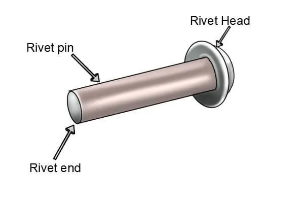
- Riveting is a forging process that may be used to join parts together by way of a metal part called a rivet.
- The rivet acts to join the parts through adjacent surfaces.
- A straight metal piece is connected through the parts. Then both ends are formed over the connection, joining the parts securely.
Bolting
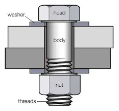
- In this metal joining process, the metallic parts are joined together by means of Bolt/Screw.
- This Process is widely used in assembling of parts are to be joined temporarily or joints which require periodic maintenance.
- Two main types of loads on bolted joints - Tension Shear Bolting.
Hemming
- Hemming is a forming operation in which the edges of the sheet are folded or folded over another part in order to achieve a tight fit.
- Normally hemming operations are used to connect parts together, to improve the appearance of a part and to reinforce part edges.
Welding
- Welding is a fabrication process that joins materials, usually metals or thermoplastics, by using high heat to melt the parts together and allowing them to cool, causing fusion.
- When heated or pressurized for a certain amount of time, metal starts melting.
- By melting the adjoining sections of two materials to be joined (base material or filler material) to make them blend together to form penetration and then cooling that section, you can join materials into one piece.
- This is the basic mechanism of welding.
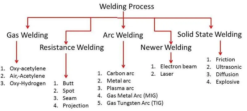
Types of Welding process
Chemical Joining
This type of joining comprise of Adhesive bonding.
Adhesive bonding
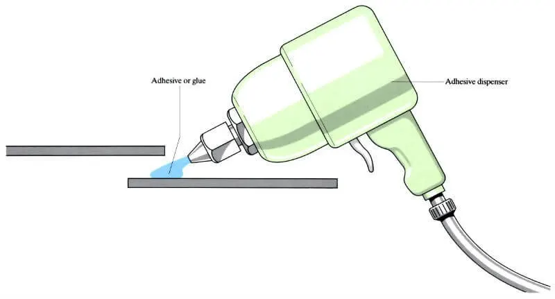
- Adhesive Bonding is the process of joining two surfaces together, usually with the creation of a smooth bond.
- This may involve the use of glue, epoxy, or one of a wide range of plastic agents which bond either through the evaporation of a solvent or through curing via heat, time, or pressure.
3.Resistance Welding
Rsistance welding is a technology is awelding technology widly used in manufacturing industry for joining metal sheets and components.
The weld is by conducting a strong currnet through the metal contribution to heat up and finally melt the metals at localized points predetermined by the design of the electrods and/or workpieces to be weld.
The heat in the resistance welding process is generated by the resistance offered by the work pieces to the flow of low voltage high density electric current.
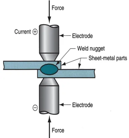
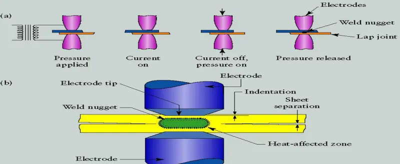
A typical resistance welding cycle consists of (1) squeeze (2) weld and (3) hold period
Types
- Resistance Spot Welding
Importance: a typical car body has got app. 15, 000 spot welds.
In this process, the fusion of electrodes is done by electrodes having opposing charges at one location. The sheet thickness has to be less than 3 mm for a good spot weld.
The shape of electrode tip is important like round, hexagonal, square etc. The nugget shape will be app. 5-10 mm in this case.
Electrodes in RSW: (i) Copper based, (ii) Refractory metal (Cu, Tungsten combinations)
- Resistance Seam Welding
In principle, seam welding is similar to spot welding except that it uses disc shaped electrodes as shown in fig.
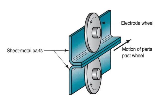
Unlike spot welding the disc shaped electrodes are not separated after each weld but maintain a continuous pressure over the work pieces.
Two common types of seam weld are Lap seam welding and Butt seam welding.
The electrode current is timed to flow in pulses so that a row of welds is produced along the interface.
- Resisitance Projection Welding
Joining metal components with sheets with embossments by directly applying forces with electrodes specially designed to fit the shapes of workpieces.
4.Fusion Welding
In fusion-welding processes, heat is applied to melt the base metals.
In many fusion welding processes, a filler metal is added to the molten pool during welding to facilitate the process and provide strength to the welded joint.
When no filler metal is used, that fusion welding operation is referred to as Autogenous weld.
Types
1. Arc welding
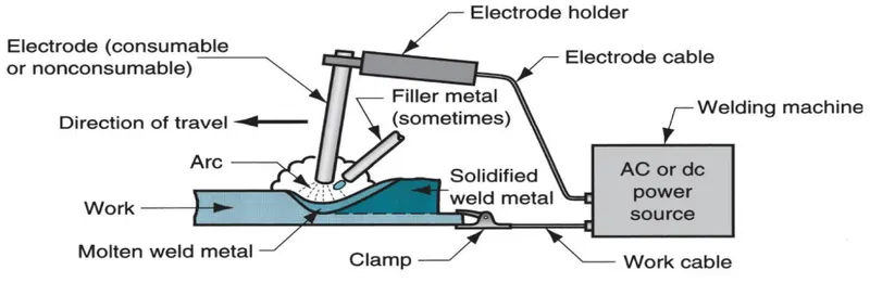
It is a fusion welding process in which the melting and joining of metals is done by the heat energy generated by the arc between the work and electrode.
An electric arc is generated when the electrode contacts the work and then quickly separated to maintain the gap.
A temperature of 5500°C is generated by this arc.
This temperature is sufficient to melt most of the metals. The molten metal, consisting of base metal and filler, solidifies in the weld region. In order to have seam weld, the power source moves along the weld line.
2. Resistance welding
Rsistance welding is a technology is awelding technology widly used in manufacturing industry for joining metal sheets and components.
The weld is by conducting a strong currnet through the metal contribution to heat up and finally melt the metals at localized points predetermined by the design of the electrods and/or workpieces to be weld.
The heat in the resistance welding process is generated by the resistance offered by the work pieces to the flow of low voltage high density electric current.
A typical resistance welding cycle consists of (1) squeeze (2) weld and (3) hold period
3. Gas welding
4. Electron beam welding
5. Laser welding
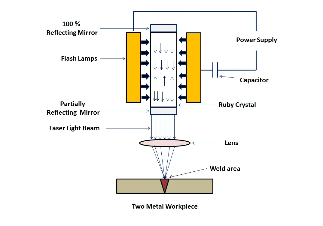
- Laser Beam Welding is a fusion welding process in which two metal pieces are joined using a laser.
- Laser Beam Welding is done by focusing the laser beam to the cavity between the two metal parts.
- The laser beam strikes the metal parts and produces heat which melts the material of the two metals or the filler material.
After cooling of the molten metal, a weld is formed which is very strong.
5. 3-2-1 Principle
Locating a part to be machined involves mainly three steps: Supporting, Positioning, and Clamping.
Two main intentions when placing a job on a jig/fixture are:
- Precisely positioning the part at the desired coordinates.
- Curbing all six degrees of movement so that the part cannot budge.
An extensively used method for obtaining these objectives is the 3-2-1 principle or six degrees of freedom for part location.
The 3-2-1 method is a work-holding principle where three pins are located on the 1st principle plane, i.e., either XY, YZ, ZX. And two pins are located on the 2nd plane perpendicular to the 1st plane, and at last, one pin on the plane is mutually perpendicular to the 1st and 2nd planes. The aim is to constrain the movement of the workpiece along all three axes.
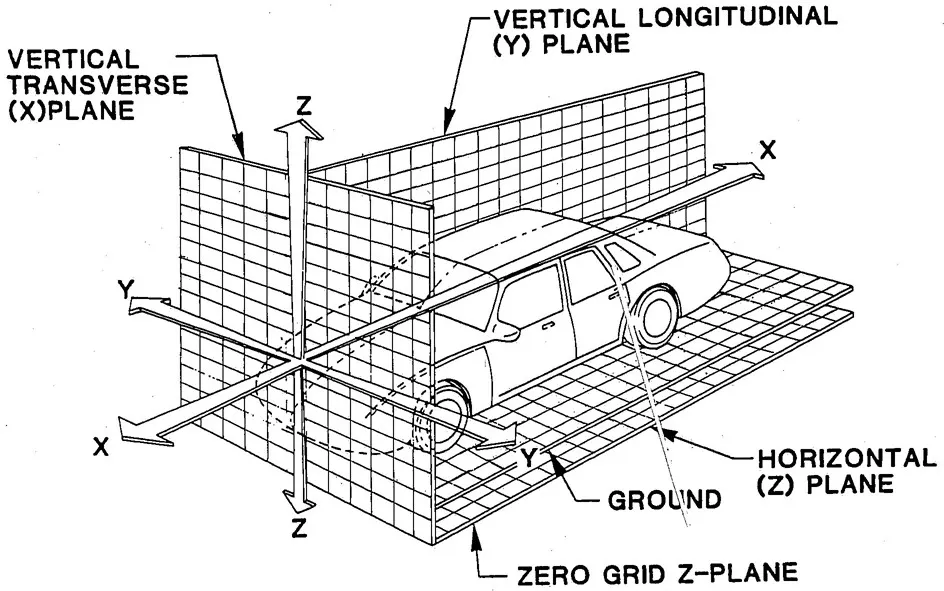
6.Body Co-ordinate System
Body coordinate system is used in the automotive industry for drawing of body parts and product design.
Coordinate systems are used to describe the position of an object in space.
A coordinate system is an artificial mathematical tool that we construct in order to describe the position of a real object.
It can also be knwon as Car line and Body line.
Car lines are the (Grid lines) shown on the fixture, which virtually represent the same location in the BIW. All the car line on fixture display the coordinate at corner for reference. With these lines one can easily relate the, location in BIW.
X = Longitudinal direction (Front O Line - FOL)
Y = Transverse direction (Center O Line - COL)
Z = Vertical direction (Bottom O Line - BOL)
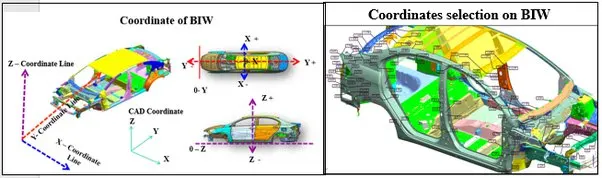
Automotive sheet metal components are designed in CAD (Computer added Design ) software e.g.CATIAv4-v5, UG, ProE, Ideas,In any CAD tool there is default axis system X,Y,Z.Lets us consider if every designer starts design of BIW Door Assembly part a default axis system,then it will be difficult to assembly or position the part with respect to each other.
7. Body Planes
Body planes are reference planes in automotive car.
These planes are used to define the GD & T of all car parts in automotive domain.
It helps in creating a standard system to work with.
It helps in locating various parts in an easy manner.
It helps in ease of access.
The measurement along FOL or X axis is known as F/A or Front Aft
The measurement along COL or X axis is known as C/C or Cross Car
The measurement along BOL or X axis is known as U/d or Up Down