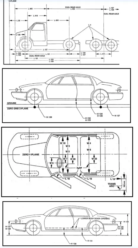
Week 2:- BiW Fixture Basics Challenge
Week 2:- BiW Fixture Basics Challenge
Q1 What is the process of project execution activity?
Project execution activities are being practiced in general projects where BIW Fixtures and tooling are involved
The key steps of project activities are as follow:
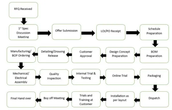
1) RFQ
It's The Request for a Quotation sent by the customer. It consists of customers' technical requirements, and study data.
2) 1st spec discussion & offer submission
RFQ helps to estimate efforts, and timeline and create a commercial and technical offer. After scope understanding with the customer Then the cost of all the operations prepared & submitted
3)PO/LOI
On submitting the offer customer will review it and release a letter of intent or purchase order with its terms and condition as stated earlier
4) Schedule Preparation
To submit the project on time project plan is prepared considering all the aspects that cause delay In the project each activity depends on the previous activity. So if the previous activity has not been completed on time it will cause a delay in the next activity date is fixed so that it will move further. Each activity has an assigned specific time i.e. when the activity is starting & when it is ending. So we have some back plan so that the final date comes to close final delivery date. There need to be proper scheduling to complete the project in time. “On-time delivery” is one of the major requirements from the customer side also customer wants commitment must be followed in respect of time.
5)BOM preparation
Bill of material is prepared for the project, like the required bought-out parts, grippers, cylinders, motors, etc.
6) Design concept preparation
A concept is prepared based on all received specifications, and data from the customer such as 3D data of car panel, drawing, drawing std., design std., manufacturing std.
7) Customer approval
After designing the concept the approval of the customer is required. The customer checks whether the design fulfills the requirements or not according to the technical offer. If yes, the customer approves the design or will also ask for some addition or changes in the design. By doing the necessary modifications final approval is taken from the customer.
8) Detailing & DWG release
After the approval from the customer, technical drawings are released which show the detailed specifications of all the parts required.
9) Manufacturing BOP ordering
The BO parts like motors, cylinders, sensors, gripper, etc. required for manufacturing are ordered per the design specifications.
10) Mechanical/ Electrical assembly
Once the parts are received the prior Quality control checking is held. All the parts are checked as per the specification. After QC studying the Mechanical or electrical assemblies are prepared as per the design instructions.
11)Quality inspection
After the assembly again the quality is checked. All the dimensions, positional accuracy, and coordinates are checked using the CMM machine.
12) Internal trial & testing & online trial
After the quality inspection, internal tryouts are taken to confirm whether the fixture can do the desired operation. The simulation is done for this purpose at an early stage. In this, the fixture is checked for the clamping of the part, welding, proper loading & unloading of the part, etc.
After this online trial is taken in which all the operations are accomplished in automated mode by using electrical connections. The process sequence is checked as per the defined way in design in automated mode. The customer is also involved in an online trial to taking approval.
13) Packaging & dispatch
To prevent damage to the fixtures in transportation, the assemblies are packed in a proper manner. Once the packaging is done the fixture is dispatched to the customer location.
14) Installation as per layout
According to the functionality, application, and process sequence layout is prescribed for the parts like fixtures, and robots. The layout is done at the very initial level & according to that installation is done.
15) Trials & training at the customer
After the proper installation production trials are performed at the customer end. The trials are done to demonstrate the capability of the fixture to the customer. After the trials, the training on the process sequence is given to the operator and engineer.
16) Buy-off meeting & Final handover
After production trial & training Customers, Sometimes customers raise some additional requirements, after addressing all the points, the project is finally handover to the customer.
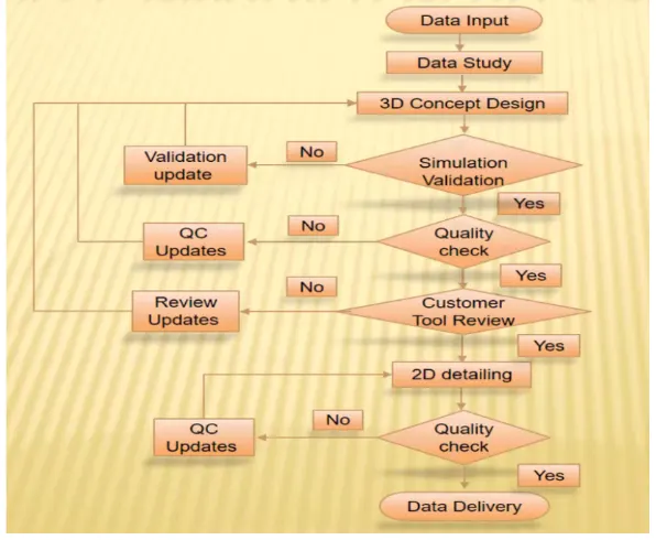
Process Flowchart in fixture design
-----
Q2. What are the types of joining processes?
Moreover, in automotive The entire body is not possible to manufacture in one piece, Hence Designer uses different joining processes to combine sheet metal panels.
Joining processes are:
- Metallurgical Joining
- Mechanical Joining
- Chemical Joining
Metallurgical Joining is classified into:
- Welding
- Brazing
- Soldering
- WELDING:
Welding is a method that permanently joins different metals and alloys together.
The heat used to melt the parts together and allow them to cool causes fusion.
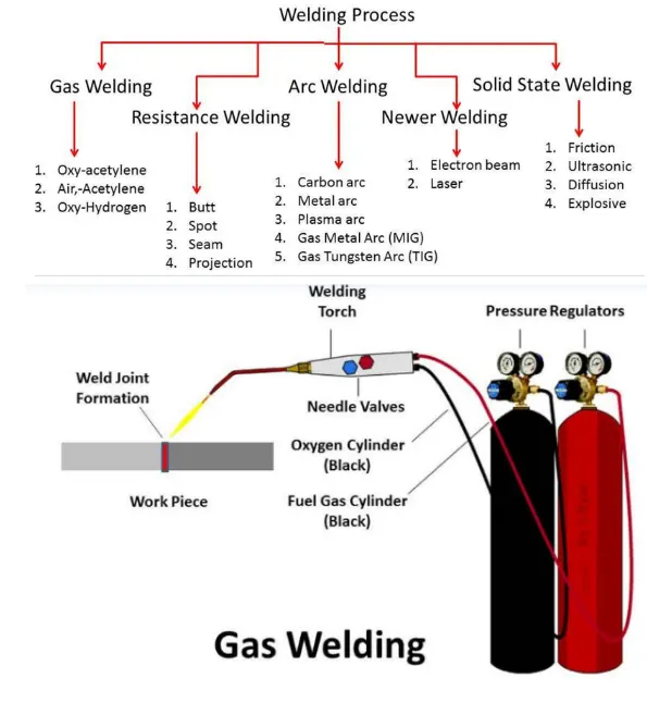
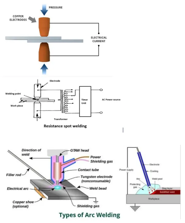
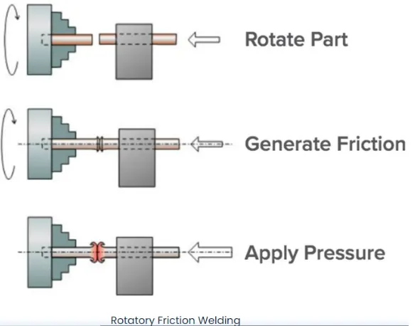
There are different kinds of welding operations.
Brazing:
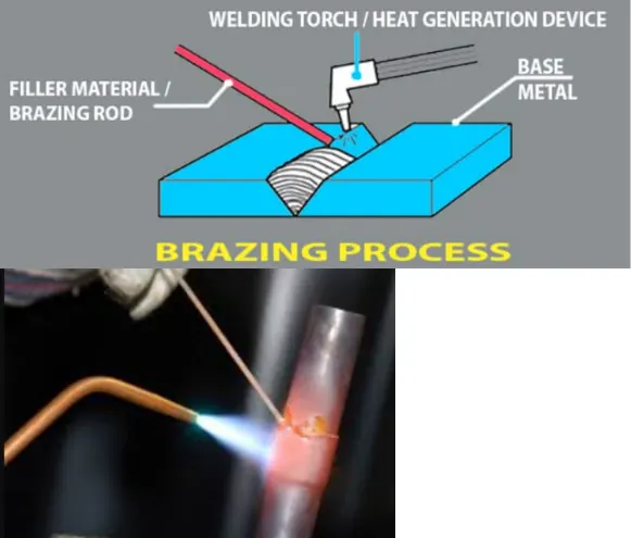
Brazing is a group of welding processes that produces coalescence of materials by heating to a suitable temperature and using a filler metal having a liquid above 840ºF (449ºC) and below the solidus of the base metals.
The filler metal is distributed between the closely fitted surfaces of the joint by capillary attraction.
Brazing is distinguished from soldering in that soldering employs a filler metal having a liquid below 840ºF (449ºC).
When brazing with silver alloy filler metals (silver soldering), the alloys have liquidus temperatures above 840ºF (449ºC).
Brazing is only used on ferrous metals because the solder melts at 960 degrees Celsius, a point above the melting point of non-ferrous metals.
Soldering
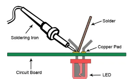
Soldering is a joining process that joins different types of metals together by melting solder. Solder is a metal alloy, usually made of tin and lead, that is melted with a hot iron. The iron is heated to temperatures above 600 degrees Fahrenheit, which then cools to create a strong electrical bond.
In contrast to welding, the workpieces are not melted when soldering.
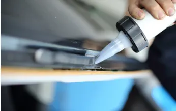
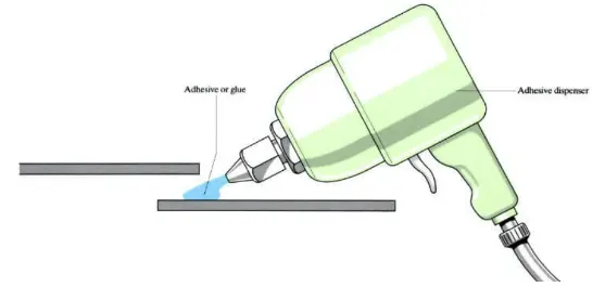
Adhesive bonding:
Adhesive Bonding is the process of joining two surfaces together, usually with the creation of a smooth bond.
This may involve the use of glue, epoxy, or one of a wide range of plastic agents which bond either through the evaporation of a solvent or through curing via heat, time, or pressure.
Diffusion bonding:
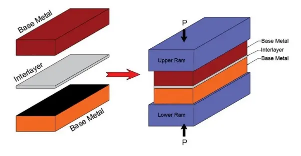
Diffusion bonding is a welding technique that is primarily used in metal working.
Diffusion bonding operates on the principle of solid-state diffusion and makes it possible to join two similar or dissimilar metals.
2.Mechanical joining:
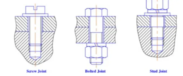
Mechanical joining is a process for joining parts through clamping or fastening using screws, bolts, or rivets
A drawback of using mechanical joining is the lack of a continuous connection between parts, because the joint is achieved through discrete points. Also, holes created for joining are vulnerable to fractures and corrosion.
Types of Mechanical joints are as below:
A.Fastener joint
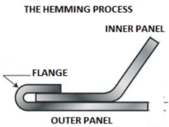
B. Rivet joint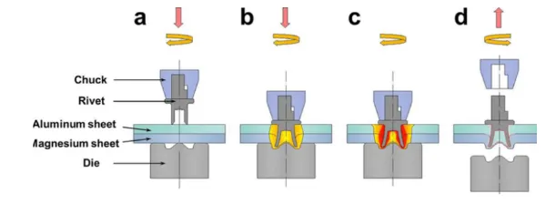 C. Hemming & seaming process:
Q3 What are Resistance Welding & its application in the automotive sector?
Resistance welding technology is widely used in the manufacturing industry for joining Metal Sheets and components by conducting a strong current through the metal combination of heat and finally melting the metals in a localized area
The working principle
Resistance welding such as seam, spot, and protection works on the same principle. Whenever the current flows through electric resistance, then heat will be generated.
The generated heat will depend on the material’s resistance, applied current, conditions of a surface applied, and the current time period.
The following metals may be welded by Resistance Welding:
- Low carbon steels - the widest application of Resistance Welding
- Aluminum alloys
- Medium carbon steels, high carbon steels, and Alloy steels (may be welded, but the weld is brittle)
Advantages of Resistance Welding:
- High welding rates
- Low fumes
- Cost-effectiveness
- Easy automation
- No filler materials are required
- Low distortions
Disadvantages of Resistance Welding:
- High equipment cost
- Low strength in case of discontinuous welds
The most common type of welding used in BIW joining process is resistances welding. This type of resistances welding is
- Spot Welding.
- Seam Welding.
- Projection Welding
- Spot Welding.
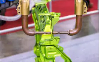
Spot welding is the simplest type of welding where the work portions are held jointly below the force of the anvil face. The copper (Cu) electrodes will make contact with the work portion & the flow of current through it
- Seam Welding.
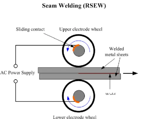
Seam welding is the joining of workpieces made of similar or dissimilar materials along a continuous seam.
Seam welding is used in clouser components where leakage of air or fuel needs to be prevented
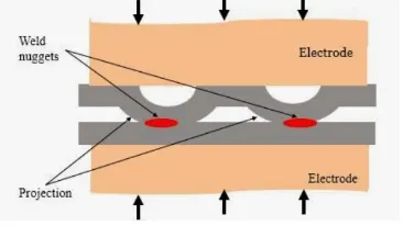
3.Projection Welding
As the name suggests, Projection Welding is used for welding multiple projections on the workpiece.
These projections can be circular, round dimples, extended corners, rib type, or elongated ridges of weld nuts.
Question 4: What is fusion welding & types of fusion welding with their application in the automotive sector?
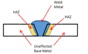
Fusion welding.
Processes use heat to melt the base metals. In many fusion welding operations, a filler metal is added to the molten pool to facilitate the process and provide bulk and strength to the welded joint.
The fusion category includes the most widely used welding processes, which can be organized into the following general groups:
GAS WELDING
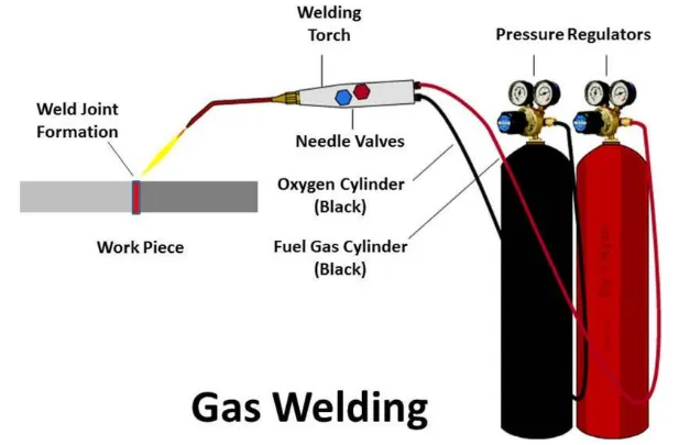
Gas welding is a welding process thatmelts andjoints metals by heating themwith a flame caused by a reaction of fue lgas and oxygen.
The most commonly used method is Oxyacetylene welding, due to its high flame temperature.
Advantages-
Simple equipment
Portable
Inexpensive
Easy maintenance & repair
ARC WELDING:
The most popular type of fusion welding is arc welding. Arc welding lives up to its namesake by relying on an electric arc to join two or more objects. With electric arcs measuring up to 6,000 degrees Fahrenheit, this fusion welding process is highly capable of melting even the toughest metals. Furthermore, arc welding can be performed underwater, making it an ideal solution for offshore welding projects.
Metal Inert Gas welding(MIG):
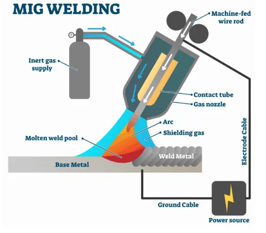
MIG (Metal Inert Gas) welding is a welding process in which an electric arc forms between a consumable wire electrode and the workpiece. This process uses inert gases or gas mixtures as the shielding gas. Argon and helium are typically used for the MIG welding of non-ferrous metals such as aluminum.
MIG welding allows for the fast production of high-quality welds and, due to a lack of flux being used, there is no chance of slag being trapped in the weld metal. The disadvantages of MIG welding are that it cannot be performed in a vertical or overhead position, due to the high heat and fluid nature of the weld pool. Also, the equipment used by a MIG welder can be complex.
MIG is used in the fabrication of sheet metal and also can be used for deep groove welding.
Tungsten inert gas welding (TIG):
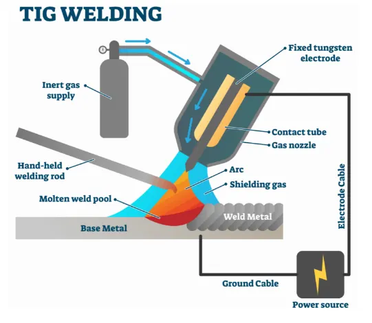
In the TIG welding process, the arc is formed between a pointed tungsten electrode and the workpiece in an inert atmosphere of argon or helium. The small intense arc provided by the pointed electrode is ideal for high-quality and precision welding. Because the electrode is not consumed during welding, the TIG welder does not have to balance the heat input from the arc as the metal is deposited from the melting electrode. When filler metal is required, it must be added separately to the weld pool.
TIG welding is applied in all industrial sectors but is especially suitable for high-quality welding. In manual welding, the relatively small arc is ideal for thin sheet material or controlled penetration (in the root run of pipe welds). Because deposition rate can be quite low (using a separate filler rod) MMA or MIG may be preferable for thicker material and for fill passes in thick-wall pipe welds.
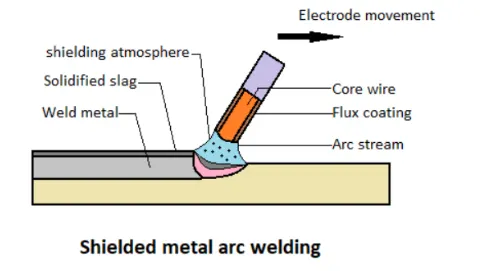
Shielded Metal Arc Welding:
Shielded Metal Arc Welding, otherwise known as manual metal arc welding or flux shielded arc welding, is a process that uses a flux-coated electrode to form the weld. As electricity passes through the electrode, the flux forms a gas, which shields the electric arc in the space between the electrode and the metal being welded, preventing contamination from atmospheric gasses in the weld. This process is fairly simple and doesn’t require much in the way of specialized equipment.
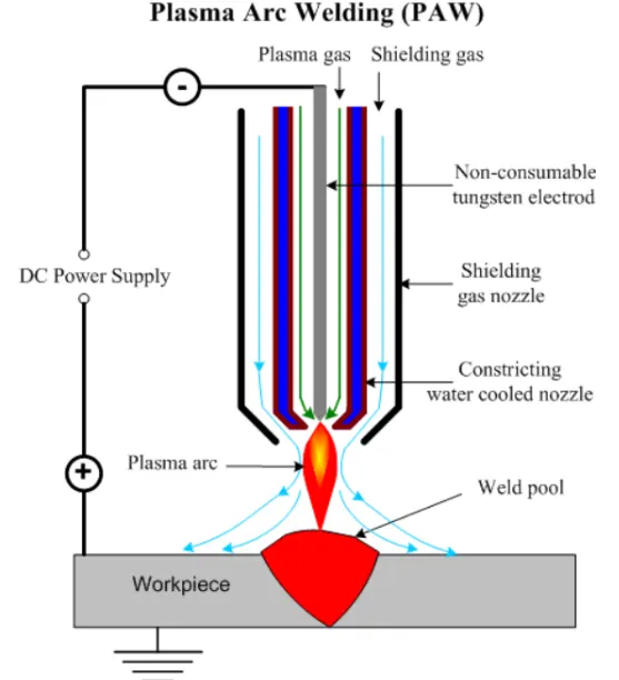
Plasma Arc Welding:
This process uses an electric arc created between an electrode and the torch nozzle. The electric arc ionizes the gas in the chamber creating plasma. It is then forced through a fine boring copper nozzle that directs the arc to the workpiece, allowing the plasma arc to be separated from the shielding gas.
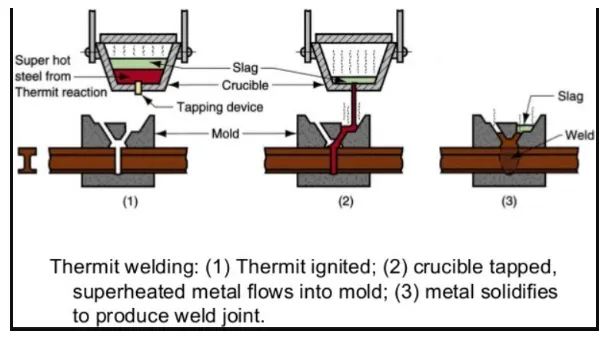
Thermit Welding:
Welding the parts by using liquid thermit steel around the portions to be welded is called thermit wielding.
Since it is a fusion welding process, neither arc is produced to heat parts nor flames are used. Welding principle is the heat of the thermit reaction used for welding in plastic state & mechanical pressure is applied for the joint.
It is depending on the chemical reaction between iron oxide & aluminium, The reaction in thermit welding is 8Al + Fe3O4 = 9Fe = 4Al2O3. This reaction takes place about 30 sec only and the heat liberation temperature is about 2800-degree Celsius. It is twice the melting temperature of steel.
Automotive application of arc welding technology:
Arc welding is used to weld the chassis parts in automotive industry.
Arc welding is used to weld body parts in automotive industry. Low heat input welding of thin steel sheets prevention of burn through due to excessive heat input is important in the welding of car body parts of thin sheets. For this reason, thin welding wire with a diameter of 0.9mm, which enable welding at low currents & low heat input welding power source.
TIG welding is used to join thin stainless-steel parts & various piping parts in automobile industry. TIG welding can work on both AC and DC power sources. One of the greatest strengths of TIG welding is that it can be used for welding non-ferrous metals like aluminium, copper, magnesium, copper, nickel, titanium etc.
MIG welding is used for repairing work In automobile industry. To repair especially to dismantle & reassemble with new parts. Example to rebuild an old car. When It comes to fixing broken parts in the field, there are three steps to master: cutting & removal of the failed component, preparation of the new joint/part, welding & clean-up.
Worn parts can be repaired using MIG welding in variety of coating (stainless steel, bronze, nickel, aluminium or hard surfacing) & in a range of hardness, for a fraction of the cost of purchasing a new part.
Question 5: What is the 3-2-1 principle?
Answer:
Degrees of freedom:
The degree of freedom defines as the capability of a body to move. Consider a rectangular box, in space the box is capable of moving in twelve different directions (six rotational & six axial).
6 translational degrees of freedom: +X, -X, +Y, -Y, +Z, -Z.
And 6 rotational degrees of freedom:
1- Clockwise around X axis (CROT-X).
2- Anticlockwise around X axis (ACROT-X).
3- Clockwise around Y axis (CROT-Y).
4- Anticlockwise around Y axis (ACROT-Y).
5- Clockwise around Z axis (CROT-Z).
6- Anticlockwise around Z axis (ACROT-Z).
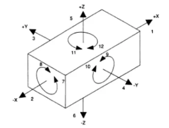
Each direction of movement is counted as one degree of freedom. i.e. a body in space has twelve degree of freedom.
Above figure shows a body in space & its possible direction of movement. The body can move two directions along the each axis of three mutually perpendicular axes; also can rotate about this axis either clockwise or anticlockwise. There are twelve degree of freedom for body in space.
In machining process, in order to attain specific results, the degrees of freedom is constrined by using work holding devices, jig & fixture & locating devices. There must be a definite relationship between cutting tool & surface of workpiece in order to perform the accurate cutting operation. To achieve high precision in machining, the workpiece must be located accurately; it is called locating of workpiece. Location of components is significant to the design of jig & fixture so that it influences the accuracy of final product. The locating device designed so that each successive workpiece loaded must occupy the same position in work handling devices.
Locating: the positional & dimensional relationship between workpiece & cutting tool.
Locator: the device to establish & maintain the position of the workpiece in work holders such as jig & fixture to ensure repeatability of work holder.
The best & most effective method of part location is 3-2-1 principle. Holding fixtures used in assembly operations often follow a 3-2-1 locating scheme to position parts. Under this scheme, three locators position a part in a primary plane or direction (e.g., high/low). Two locators then position the part in a secondary direction (e.g., in/out), leaving one locator for the tertiary direction (e.g., fore/aft). This approach fixes the part in 3-dimensional space and satisfies the six degrees of freedom constraint.
(3) minimum plane: Three locator blocks to establish part plane. Three locator or supports are placed under the workpiece. Three locators are usually positioned on primary locating surface. This restricts one axial movement downward, & 4 radial movements. Together, the three locators restrict five degrees of freedom.
(2) Round locating pin in a round hole that defines location in four directions (4 ways) perpendicular to the plane previously established. This restricts four axial movements.
(1) Round locating pin in slot that defines two of the other pin (2-way). This restricts two axial movements.
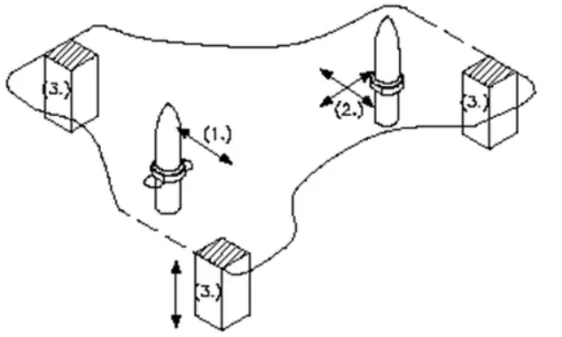
The better way of understanding of 3-2-1 principle that considers 12 degrees as of 6 degrees of freedom. It include clockwise & anticlockwise as one rotation. Movement in +ve & -ve direction as one translation motion. So we have three translation motion in x, y, z axis & three rotational motion about x, y, z axis.
In this, (3) means restricting three degree of freedom as translation motion in z axis i.e. upward & downward, two rotational motion about x & y axis.
Secondly, (2) means restricting two degrees of freedom. Translation motion in x (i.e. +ve or –ve) & y direction i.e. (+ve or –ve) &
(1) means restricting one degrees of freedom i.e. rotational motion about z axis clockwise or anticlockwise. So car panel or body cannot move in any direction with or without application of external force so properly fixed in fixture. This is basic concept of designing fixture.
Conclusion:
The jig and fixture are tools used for holding the work piece in a correct location for mass production. Various types of fixtures (like drilling fixtures, milling fixtures, and welding fixtures) are used in industry. The 3-2-1 method is the fundamental principle for all types of fixture design.
Question 6: Define body co-ordinate system?
Answer:
BODY COORDINATE SYSTEM (Part Locating System)
The body coordinate system has been widely used in the automotive industry for drawing of body parts, product & process design. A coordinate system is a reference system consisting of a set of points, lines & surfaces, used to define the positions of points in space in either two or three dimensions.
In general BCS is also called as car line & body line. Car lines are the (grid lines) shown on the fixture, which virtually represent the same location in BIW. All the car line on fixture displays the coordinate at the corner for reference. With these lines one can easily relate the location in BIW. Sometimes single coordinate hole is given in a fixture that also represents the car line coordinates, from that reference point fixture is made & can be inspected. Body coordinate are mentioned near hole. Below figure show car line on fixture.
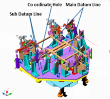
Automotive sheet metal components are designed in CAD (Computer aided Design) software e.g. CATIAv4-v5, UG, ProE, Ideas, In any cad tool, there is a default axis system X, Y, Z.
Lets us consider if every designer starts the design of the BIW Door Assembly part a default axis system, then it will be difficult to assembly or position the part with respect to each other. Due to avoid this issue, BIW car panels are designed with reference to car axis means at their Original position of the final car built.
Reference axis system of the software is used for the design of the various features of the parts (e.g. hole, fillet, threads,) To correlate the position of all the automotive components during the final assembly the axis system of the vehicle is used. Most of the time vehicle axis system and software axis system is the same. e.g. In most of European OEM, The X-axis represents the length of the vehicle Y-axis represents the width of the vehicle Z-axis presents the height of the vehicle. Y-axis is considered to be located at the front axle.
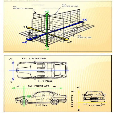
All BIW welding fixtures are designed with reference to the car line These datum schemes provide a reference system for all part surfaces and features using body coordinates. Figure below illustrates a typical body coordinate system. This system replaces the traditional X, Y, and Z directional designations with fore/aft (X), in/out (Y), and up/down or high/low (Z). The 0,0,0 point of the car is the front, lower, and center position.
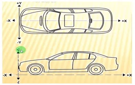
VEHICLE ORIENTATION:
All vehicle product drawings are identified numerically relative to three vehicle planes described and shown below.
X= longitudinal direction (fore & after-F/A) or (Front O line-FOL).
Y= transverse direction (Cross car-C/C) or (Centre O line-COL).
Z= Vertical direction (Up & down- U/D) or (Bottom O Line-BOL).
The origin of the body coordinate system (OX) is defined at the front centre of a vehicle. It indicates a length of car & the coordinate system (OZ) is below its underbody indicates height of car & the coordinate system (OY) its starting point is center of car body indicates width of the car.
Maintaining X,Y & Z coordinates in fixture is very important factor.
Question 7: Elaborate Body plane system & its essentials?
Answer:
Body planes are the reference plane in an automotive car. These planes are used to define the GD&T of all car parts in a automotive domain. Body planes are three mutually perpendicular imaginary planes. These are generally considered to be present at the driver position or sometimes at the engine location or at the front end of the car depending on the customer.
The measurements from the body planes to the parts are called as body line dimension.
These body planes are called as
FOL Front “O” line.
COL Centre “O” line.
BOL Body “O” line.
The measurement along FOL or X – axis is called as F/A Front aft.
The measurement along COL or Y – axis is called as C/C Cross Car.
The measurement along BOL or Z – axis is called as U/DUP down.
In below fig origin is somewhere below driving sheet as it depends or changes from customer to customer. But axis system is commonly same. Bodyline dimensions are essential for the reasons stated below.
It defines the exact position of each product in the vehicle w.r.t a fixed origin. It ensures flawless design for assembly. While designing lines, all the designs are carried out relative to the bodyline, viz, fixture, turn table etc. It assists in easy location of different parts in a vehicle. It aims in creating a standardized system. It assists in quality checks. These are basic essential thing that body line dimension would help in BIW. It could help in designing lines like welding lines, assembly lines or car body through fixture & turntable etc. This help in designing every tools. Particular assembly or parts are designed w.r.t body lines or an axis system or car line also helps in quality while doing CMM of that system. CMM is basically done with the help of coordinate. It has related particular fixture with that car part, because that dimension, coordinates of hole & pin should match so it will help in quality check also. we just give co-ordinates that belong to that hole both coordinates should match, with this matching means quality is approved.