Week 2:- BiW Fixture Basics Challenge
1) What is the process of Project Execution Activity?
- Project Execution is the performing the project scope of works and activities in accordance with the project baselines, plans, procedures, and resources for the project interface, change, schedule, cost, risk, quality, safety and environment management, and other contractual requirements. The key success factors for the project execution are well defined project definitions, roles and responsibilities, organized and building the team works, and accurate status reporting including forecast, timely decision making under the leadership of the project managers controls within internal and external organizations.
- Plan is a set of the intentional or strategic work processes that explains what to do, when, how and by whom to achieve the goals and objectives. The Plan is a formalized and commonly understood by organizational members to accomplish the project task or work.
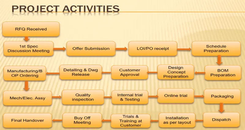
- RFQ (Request for Quote)
This Where we get the requirements from customer and will be brainstorming with top level management in the organization whether to take this project or not
- 1st Spec Dicussion Meeting
This will be the 1st level meeting with the customer where only top level management team form the organization discuss with customer and will understand there requirements.
- Offer Submission
After the previous step, the organization based on previous experiences will try to quote Project estimated cost to customer.
- LOI / PO Receipt
After approval from customer, in order to start the project we will receive 1st level PO receipt from customer.
- Schedule Preparation
After accepting the project, the organization schedules a estimatedtime plan for completion of all the activities in the project.
- BOM Preparation
Based on the project requirements, the team will 1st list of all the required items (like mechanical parts, electrical parts etc) in order for the product to be fully functional.
- Design Concept Preparation
Based on customer requirements, a concept design is being prepared.
- Customer Approval
Based on the preliminary design, the same will be submitted for customer approval.
- Detailing and Drawing release
After approval from customer, detail design will be initiated and drawings will be prepared.
- Manufacturing
After Drawing the same will be shared to manufactures for manufacturing the same
- Mechanical and electrical assembly
After manufacturing, the same will be assembled at production place for testing the product.
- Quality Inspection
After assembling, the quality of the assembled product will be tested based on standards.
- Internal trial and testing
Internally the product will be tested for checking whether it meets customer functional requirements.
- Online Trial
Online trial is where the all internal tests and reports will be submitted to customer for there approval before it is being delivered to them.
- Packaging and Dispatch
The final product is packed and delivered to customer site.
- Installation as per Layout
The product will be installed at customer site as per his layout
- Trials and Training at customer
After installing at customer site, the same will be tested to check whether the functionality requirements are being achieved.
- Buy Off Meeting and Final Handover
After this the product is successfully delivered to customer and this will lead to final meeting with customer
2) What are the types of joining processes?
- Metal Joining is defined as joining of 2 metal parts either temporarily or permanently with or without application of heat or pressure.
- Classification of metal joining process
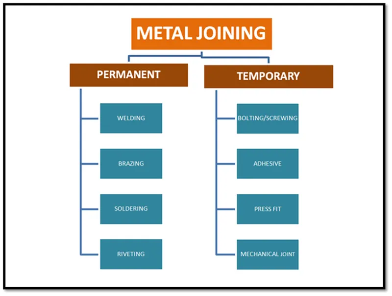
1. Permanent Joints
a) Welding
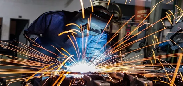
o Welding is a fabrication process whereby two or more parts are fused together by means of heat, pressure or both forming a join as the parts cool. Welding is usually used on metals and thermoplastics but can also be used on wood. The completed welded joint may be referred to as a weld-ment. Some materials require the use of specific processes and techniques.
o A number are considered 'unweldable,' a term not usually found in dictionaries but useful and descriptive in engineering. The parts that are joined are known as a parent material. The material added to help form the join is called filler or consumable. The form of these materials may see them referred to as parent plate or pipe, filler wire, consumable electrode (for arc welding), etc.
o Consumables are usually chosen to be similar in composition to the parent material, thus forming a homogenous weld, but there are occasions, such as when welding brittle cast irons, when a filler with a very different composition and, therefore, properties is used. These welds are called heterogeneous. The completed welded joint may be referred to as a weldment.
b) Brazing
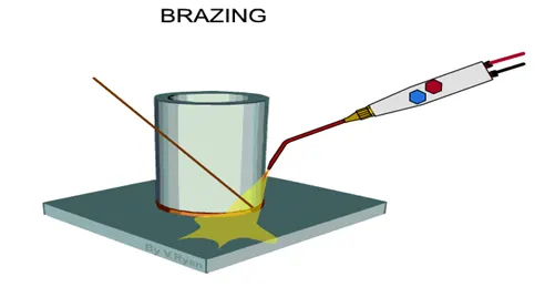
o Brazing is a joining process traditionally applied to metals (but also to ceramics) in which molten filler metal (the braze alloy) flows into the joint. The melting point of the filler metal is above 450°C, but always below the melting temperature of the parts to be joined, which distinguishes the process from welding where high temperatures are used to melt the base metals together. The filler metal, while heated slightly above melting point, is protected by a suitable atmosphere which is often a flux.
o The molten filler metal cools to join the work pieces together providing a strong join between similar or dissimilar metals. The atmospheres in which the brazing process can be undertaken include air, combusted fuel gas, ammonia, nitrogen, hydrogen, noble gases, inorganic vapours and vacuum, using a variety of heating sources such as torch, furnace, and induction coil.
o To achieve a sound brazed joint, the filler and parent materials should be metallurgically compatible, and the joint design should incorporate a gap into which the molten braze filler can be drawn or distributed by capillary action. The required joint gap is dependent on many factors, including the brazing atmosphere and the composition of the base material and braze alloy.
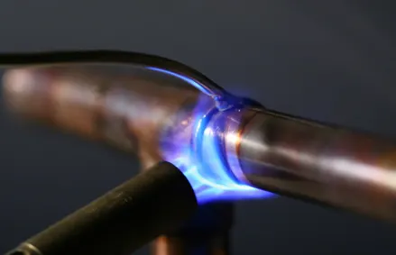
c) Soldering
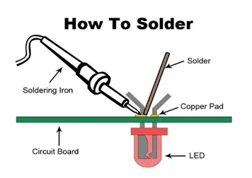
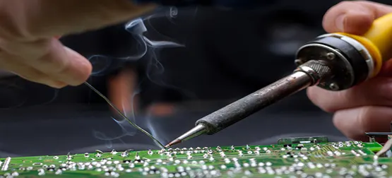
o Soldering is a joining process used to join different types of metals together by melting solder. Solder is a metal alloy usually made of tin and lead which is melted using a hot iron. The iron is heated to temperatures above 600 degrees Fahrenheit which then cools to create a strong electrical bond.
Solder is melted by using heat from an iron connected to a temperature controller. It is heated up to temperatures beyond its melting point at around 600 degrees Fahrenheit which then causes it to melt, which then cools creating the soldered joint.
o Filler metals used in soldering were once lead based (lead solder), however, owing to regulations, lead-based solders are increasingly replaced with lead free solders, which may consist of antimony, bismuth, brass, copper, indium, tin or silver.
o Occasionally at the site of the joint, there are impurities such as oil, dirt or oxidation, the flux helps prevent oxidation and can sometimes chemically clean the metal. The flux used is rosin flux which helps the mechanical strength and electrical contact of electrical joints. Sometimes it is also possible to apply a ‘wetting agent’ to reduce the surface tension.
d) Riveting
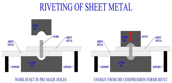
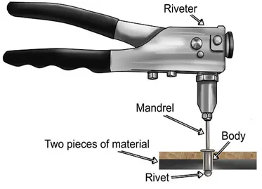
o A rivet is a permanent mechanical fastener typically characterized by a cylindrical body with a head on one end. It is typically used to join two metal plates together. Since the bond created by a rivet is practically permanent, it is often used as an alternative to adhesive-bonded or welded joints. If a riveted connection needs to be undone, the rivet must be destroyed by removing one of either of the two rivet heads.
o There are three basic parts to a rivet. Its main cylindrical body, called the shank, pierces through the two parts being fastened together. On one end is the forged head which provides a fastener to the two parts. On the other end is the tail, which needs to be bucked to set the rivet in place.
o A rivet is typically made of carbon steel, but lightweight alternatives like aluminum and copper are also used quite commonly. The primary purpose of a rivet is to support shear loads oriented perpendicular to the axis of the shank. However, it can also support tension loads at a limited capacity. For larger tension loads, bolts and screws are more recommended.
2. Temporary joints
a) Bolt/Screwing
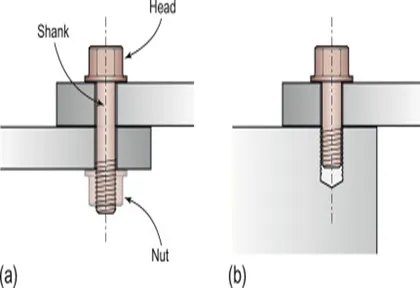
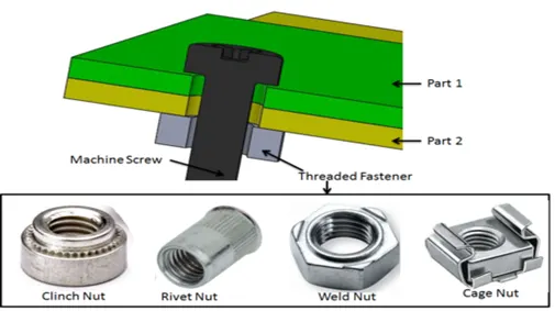
o In short, a bolt has machine threads that securely fasten inside a nut or other set of interlocking threads. There are literally hundreds of different types of bolts and fasteners. The applications are almost limitless. You can use nuts and washers on through-holes or drill and tap your own holes.
o There are temporary and permanent bolts. Thread locking compounds of varying strengths are also popular which can range from semi-permanent to fully permanent.
o If you are looking to fasten two parts together securely but aren’t quite sure if it will be a permanent solution, bolts might be the way to go
b) Adhesive bonding
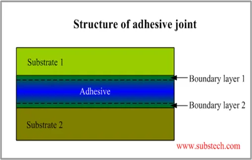
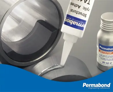
o Adhesive Bonding is the process of joining two surfaces together, usually with the creation of a smooth bond. This may involve the use of glue, epoxy, or one of a wide range of plastic agents which bond either through the evaporation of a solvent or through curing via heat, time, or pressure. With this technique, components are connected with adhesives.
o The wide range of adhesive types available allows a wide variety of materials to be glued together in products as diverse as vehicles, cell phones, personal care products, buildings, computers, and medical devices. Adhesives have tended to create relatively weak bonds, but with the use of new self-curing adhesives, these bonds now come close to the strength of the materials themselves.
o As a result, gluing is now the preferred method of joining for many applications, especially when the joint is no longer exposed to heat or weathering.
c)Press fit
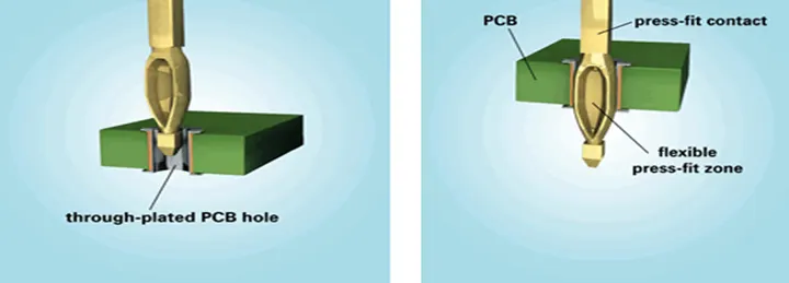
o Press-fit technology is a solder-free electrical-mechanical connection technology between component and circuit board. For this purpose, a press-fit pin is pressed into the through-hole plating of the circuit board. At the contact points between the pin and the hole wall, gas-tight zones are created by cold welding the contact materials
d) Mechanical joint
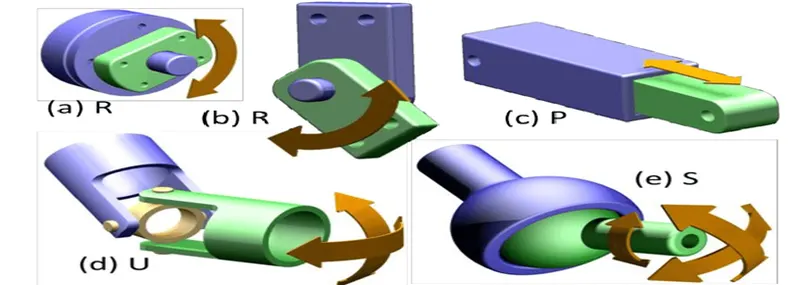
o A mechanical joint, as the name suggests, is a type of joint that connects or more mechanical surfaces. Machines such as lathes and milling machines often contain hundreds — sometimes even thousands — of individual moving parts. In areas where these components meet, a mechanical joint may be used.
o The defining characteristic of mechanical joints is that they are used exclusively to connect multiple mechanical parts. Mechanical joints typically allow a limited range of movement, which is essential to their operation. Mechanical parts, of course, are designed to move. As a result, they must be joined in a manner that allows them to move. If they are joined with a fixed joint, the parts may seize or lock up.
o Mechanical joints allow mechanical parts to move as intended while keeping them connected at all times.
3) What is Resistance Welding and its application in automotive sector?
o The category Resistance Welding covers a number of processes in which the heat required for welding is produce by means of electrical resistance across two components to be joined. These processes have major advantages such as not requiring consumable electrodes, shielding or flux.
o The total resistance in these processes is the sum of the following properties
o The resistance of the electrodes
o The electrode -work piece contact resistance
o The resistance of the individual parts to be welded
o The work piece contact resistance.
o The actual temperature raise at the joint depends on the specific heat and the thermal conductivity of the metals to be joined. For example metals like Aluminum and Copper have high thermal conductivity and so they require high heat concentration. The magnitude of current in resistance welding operations may be high as 10,000 A. Although voltage is only 0.5V-10V.
o The heat generated is given by the equation
𝐻=(𝐼^2)𝑅𝑡
Where H= Het generated in Joules, I is input Current in A, R is resistance in Ohms, t is time in sec
Types of Resistance Welding:
1. Electro slag Welding (ESW)
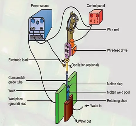
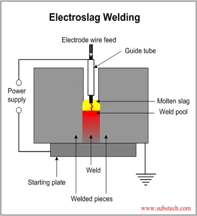
o Electro slag welding (ESW) is a fusion welding process for joining thick work pieces in a single run. This is not an arc welding process though most of the set-up is similar to the usual arc welding processes and arcing is required to initiate the process and may also occur subsequently when the process stability is disturbed.
o Apart from the conventional ESW process in which the usual electrode wire with contact tube is employed there is a popular variant of the process called Consumable Guide ESW Process. An essential feature of the ESW process is that the welding is done with weld joint in vertical position.
o Due to high heat input the weld pool in ESW is usually quite voluminous resulting in a weld with properties resembling that of a casting which makes post weld heat treatment (PWHT) essential to achieve the desired metallurgical structure to attain the required mechanical strength.
o Typically ESW is extensively used in the construction of pressure vessels, press frames, water turbines and heavy plate fabrication industries.
2. Spot Welding
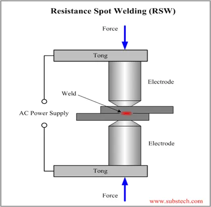
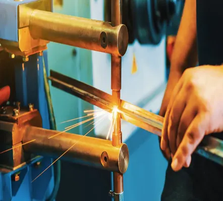
o In resistance spot welding process overlapping sheets are welded by the flow of current between two cylindrical electrodes. The main equipment for spot welding is the spot welding machine which consists of a step down transformer, a time control unit, and a pair of copper alloy electrodes.
o As voltage plays no direct role in resistance welding it is, therefore, kept low between 5 to 25 volts but the current is usually heavy (100-50,000 A); however, it flows only for a short duration of time (0.06 to 3 seconds). Application of pressure to achieve forge between the two sheets is an essential aspect of the process.
o Spot welding is mainly used for lap welding of thin sheets particularly in the welding of automobile and refrigerator bodies, and high quality work in aircraft engines.
3. Projection Welding
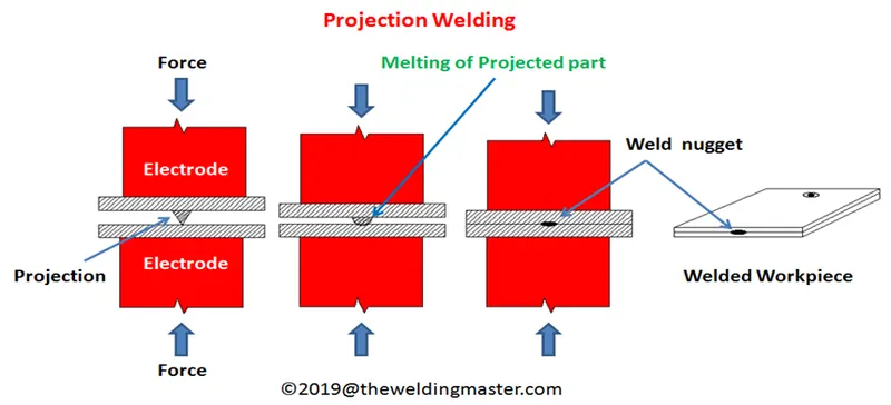
o Projection welding is a process of joining two sheets or a sheet and a thick component, or a small component like nut to a big body like automobile chassis, by making raised portions or projections on one of the components.
o The projections are made by embossing or intersection (e.g. cross of wires, etc.). There are several types of projections viz., round button or dome type, ring type, elongated projection, shoulder projection, and radius projection.
o The projections act to localize the heat of welding circuit, because when placed together the sheets touch only at the points of the projections. Projection collapses due to heat and pressure and a fused nugget is formed at the interface. Equipment used for projection welding is similar to that used for spot welding except that the rod electrodes are replaced by flat copper platens which also shows the force and current cycles for the process.
o Typical applications of the process include projection welding of reinforcing rings around holes in sheet metal tanks, welding of threaded studs to backing bar or plate and cross-wire welding. Cross-wire products include such items as refrigerator racks, grills of all kinds, lamp shade frames, wire baskets, fencing, gratings and concrete reinforcing mesh.
4. Seam Welding
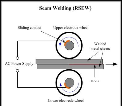
o In resistance seam welding wheel electrodes are used to produce spot welds overlapping to the extent of 25 to 50%. Due to shunting of current through the already made weld, the, current required is higher than in normal spot welding. Pressure is applied to fuse the metal properly into a nugget as in spot welding.
o Seam welding is used for producing leak-proof joints in tanks and boxes generally required for the automobile industry. This process is, however, restricted to welding thin materials ranging between 2.5 and 5.0 mm.
o Also, it is used mainly for welding materials with low hardenability rating, for example, hot-rolled grades of low alloy steels. This process is commonly used for making flange welds for use in water-tight tanks.

5. Electrical Resistance Seam Butt Welding (ERW)
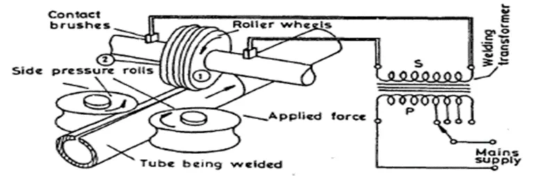
o Large quantities of steel tube and pipe are manufactured by resistance butt seam welding from strip which is continuously edge sheared and rolled into tube of desired diameter before welding. Alternating current of up to 4000 A at about 5 volt is introduced across the joint by pressure rolls. For introducing heavy current directly to the moving electrodes a rotating transformer with slip rings on the primary side is employed.
o Unlike the normal resistance seam welding, current and work motion are continuous in this process. The maximum rate of production is limited by the welding current frequency because as the welding speed is increased individual current half-cycles eventually lead to spot welding instead of seam welding.
o To overcome this difficulty current frequency is usually increased to 350 Hz to achieve welding speed of up to 36 m/min. The tube produced by this process has a fin of upset metal along the weld joint both inside and outside which is usually removed by installing appropriate cutters on the production line.
o The tube is cut to the desired lengths by employing a cutter which moves along the tube and is synchronized to cut the desired length in the available run in a given cycle.
6. Percussion Welding
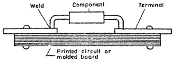
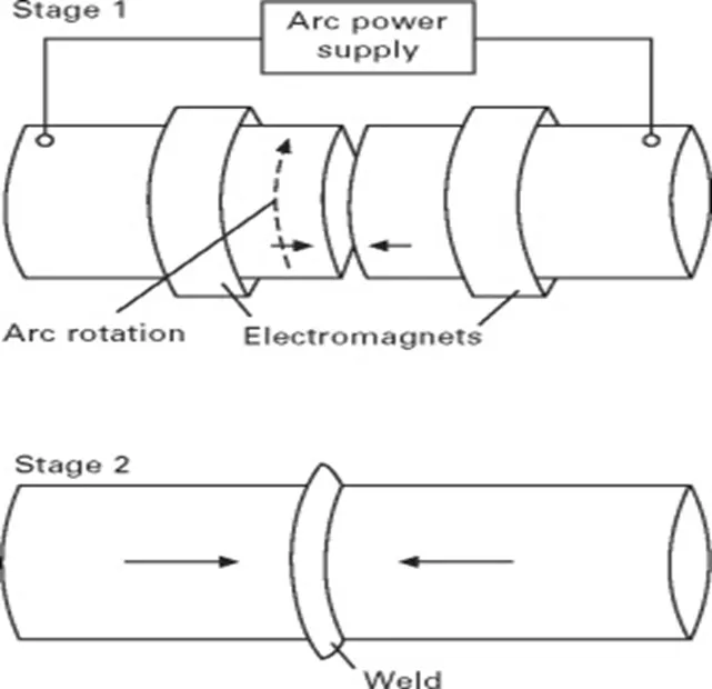
o Percussion welding is an arc welding process of joining, end-to-end, two parts of equal cross-section. The arc is produced by a short pulse of electrical energy and pressure is applied in a percussive manner to produce coalescence simultaneously over the entire abutting surface. In general percussion welding is the term used in the electronics industry for joining wires, contacts, loads and similar items to a flat surface.
o There are two variants of this process viz., magnetic force percussion welding and capacitor discharge percussion welding.
o Essential steps involved in the process involves,
a) establishing an arc between the surfaces, to be joined, with high voltage to ionize the gas between the parts or with high current to melt and vaporize a projection on the part
b) Move the part~ together percussively with an applied force to extinguish the arc to accomplish a weld. Welding heat is generated by a .high current arc between the two parts to be joined.
o The extremely short duration arc limits melting to a very thin layer 011 the two surfaces being welded. Consequently, there is very little upset or flash on the periphery of the welded joint. Filler metal is not used nor flux or special atmosphere required.
7. Butt (Upset) Welding
o In Resistance Butt Welding or Upset welding the pieces to be welded are held in clamps supported on two platens, one of which is fixed and the other moveable; and form part of the single-turn secondary loop of a heavy duty transformer.
o The ends to be welded touch each other before the current is switched on. A heavy current is then passed from one work piece to another and the contacting faces are heated up due to the contact resistance.
o The two pieces are pressed together firmly after the desired welding temperature of 870 to 925°C, for steels, is reached. The pressing action which results in the increase in lateral dimension of the work pieces is called upsetting.
o Upsetting takes place both during and after the current flow. The upsetting action results in welding of end faces with squeezing of a part of the softened metal to form a fin, which can be removed later, if required, by machining.
o Resistance butt welding is used for end joining of rods, tubes, bars, and similar other sections for welding a cross-sectional area of up to 150 mm2. Wire and rod from 1.25mm to 30 mm diameters can be upset welded.
o Typical application of resistance butt welding is in wire mills for joining wire coils to each other to facilitate continuous processing.
8. High Frequency Resistance Welding (HRFV)
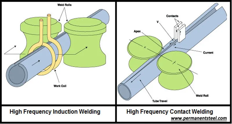
o In this process the tube is formed by rollers in the same way as in ERW process but the current in the range of 50u to 5000 A at a frequency (f) of up to 500 KHz and a voltage of about 100 volts is introduced through pr0bes made of copper alloys and silver brazed to heavy water-cooled copper mounts.
o Contact tip sizes range between 15 and 650 mm 2 depending upon the amperage to be carried. Whereas in ERW process the heat is generated mainly by the interfacial contact resistance in HFRW process it is produced by the skin effect due to which the current flows in a shallow depth of the conductor.
o Pressure rollers, to provide the forging pressure are installed a short distance down the line from the current probes. Due to the skin effect the current flow path lies along the strip through the apex of V formed by the faying surfaces melting at an angle of 4° - 7° as they close to form the tube.
o The depth of the heated region is generally less than 0.8 mm and thus affords the optimal condition for weld joint. HFRV process is used to produce pipe and tubing of diameters ranging between 12 and 1270 mm, and with a wall thickness of 0.25 to 25 mm.
o Any metal can be welded by this process with a speed range of 5 to 300 m/min depending upon the wall thickness. This process can also be used to manufacture spiral and finned tubes and pipes. Various types of serrated or folded fins can also be welded to tubes.
4) What is Fusion Welding and types of fusion welding with its application in automotive sector?
o Fusion welding methods include the welding methods in which faying parent surfaces, as well as filler material, liquefy during welding for the creation of welded beads. Therefore heat is often related to these processes.
o Outside pressure application is not needed for these processes, except for a resistance welding group where there is a need to sustain significant contact pressure throughout welding to ensure a solid joint. It may or may not be added to filler material.
Types of Fusion Welding
1)Arc Welding
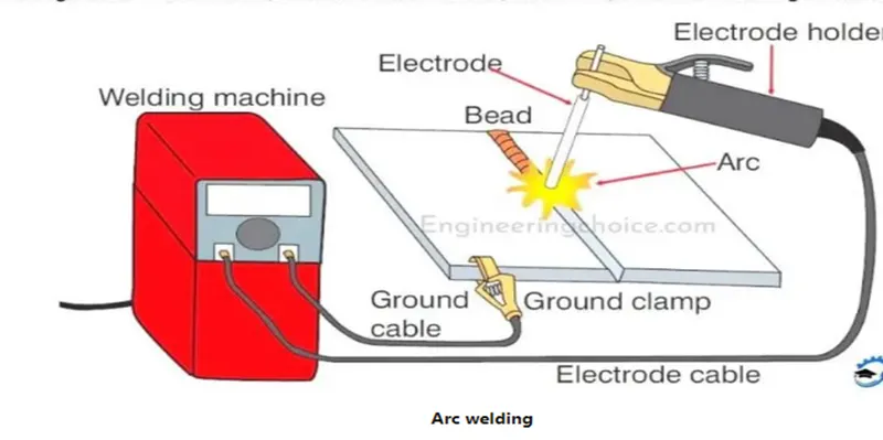
o Arc welding is a welding process used to join metal to metal by using electricity to generate enough heat to melt metal and the melted metals, when cooled, resulting in a joint of the metals. It is a type of welding that uses a welding power supply to create an arc between a metal stick (“electrode”) and the base material to melt the metals at the point of contact.
o Arc welders can use either direct current (DC) or alternating current (AC) and consumable or non-consumable electrodes. Arc welding uses an electric arc to melt the work material. First, a ground wire is attached to the material.
o Next, the welder places an electrode lead against the work material. When the welder pulls the electrode away from the material, it creates an arc, also known as a continuous plasma discharge, due to the electrical breakdown of gas.
o Arc welders use either alternating current or direct current and are used to create a very concentrated, narrow spot weld. Arc welding is a fusion welding process used to join metals. An electric arc from an AC or DC power source creates intense heat of about 6500°F, which melts the metal at the joint between two work pieces.
o The arc can either be guided manually or by machine along the joining line, while the electrode either only carries the current or conducts the current and at the same time melts into the weld pool in order to feed filler material to the joint. Since the metals react chemically with oxygen and nitrogen in the air when they are heated by the arc too high temperatures, a protective gas or slag is used to minimize contact of the molten metal with the air. After cooling, the molten metals solidify to form a metallurgical bond.
1.1)Shielded Metal Arc Welding (SMAW)
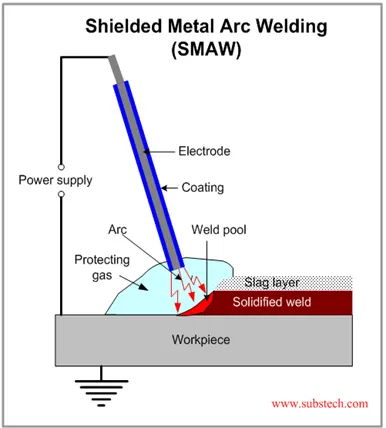
o Shielded metal arc welding (Stick welding, manual metal arc welding) uses a metallic consumable electrode of a proper composition for generating arc between itself and the parent work piece. The molten electrode metal fills the weld gap and joins the work pieces.
o This is the most popular welding process capable to produce a great variety of welds. The electrodes are coated with a shielding flux of a suitable composition. The flux melts together with the electrode metallic core, forming a gas and a slag, shielding the arc and the weld pool.
o The flux cleans the metal surface, supplies some alloying elements to the weld, protects the molten metal from oxidation and stabilizes the arc. The slag is removed after Solidification.
1.2)Metal Inert Gas Welding (MIGW)
o Metal Inert Gas (MIG) is also known as gas metal arc welding (GMAW). This type of welding is basically an arc welding process that joins two metals. This is done by heating the metals with the help of an arc.
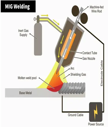
o This arc is formed between the surface to be welled and a continuously fed filler electrode. This type of welding uses a shielding gas to protect the molten pool of weld metal from reacting with elements present in the atmosphere.
o MIG welding requires a DCEP (Direct Current Positive Electrode), also known as Reverse Polarity.
o MIG welding is often called wire welding because a wire electrode is used in the process.
o A wire electrode consists of a thin wire that is continuously fed to the welding machine from a wire reel. The wire feed may be cored or solid. A cored wire consists of composites that are formed from a metal sheath with a metal filling or powdered flux, whereas solid wires are simple wires. When the trigger of the welding machine is pulled, an arc forms between the end of this wire electrode and the work piece (the metal that is being worked on).
o The arc that is formed melts both the work piece and the wire and forms a weld pool. The wire serves a dual purpose in the process of MIG welding. It serves as a heat source and filler metal for the joint – hence the name wire welding.
o The wire is continuously fed through a contact tube made of copper (the contact tip), which conducts current into the wire. To protect the filler material or the work piece from reacting with environmental elements, MIG welding uses a shielding gas. The shielding gas is supplied through a nozzle that surrounds the wire. The selection of the shielding gas depends on the material that is being welded and what it is being welded for.
o MIG welding is referred to as a semi-automatic welding process owing to the fact that the rate at which the wire is fed and the length of the arc are controlled by a power source, but the speed of travel and the position of the wire are controlled manually.
1.3)Tungsten Inert Gas Welding
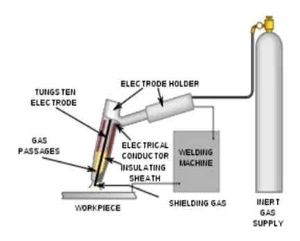
o In TIG Welding Process, TIG stands for Tungsten Inert Gas. TIG is also known as Gas Tungsten Arc Welding (GTAW). It is a process that uses a non-consumable tungsten electrode to form the weld. Generally, it uses filler metal but in some autogenously weld, it does not require it. To protect the weld area from atmospheric contamination, helium or argon is used as a shielding gas. A constant-current welding power supply is used to produce the arc between the electrode and the work piece.
o In the TIG welding process or Gas Tungsten Arc Welding, the welding torch is connected to a constant current welding power supply and shielding gas source.
o With the help of the constant current supply, the electric arc is produced between the electrode and two metal work pieces which are to be joined.
o A filler metal is used to join the two metal pieces together. As the spark is struck, the filler metal is inserted in the cavity, and due to intense heat, the filler metal melts and fills the cavity between the two metal pieces and forms a strong weld.
o A shielding gas (He or Ar) is used to protect the weld from atmospheric contaminations. As the arc is produced, simultaneously the shielding gas also starts to spread near the weld area and avoids the weld to combine with atmospheric air and protect it from contaminations.
o The welding is performed by a highly-skilled operator. The operator has better control over the weld. He can use both hands to control heat generated and filler metal. From one hand he controls the arc produced and with the other hand he controls the feed of filler metal.
1.4)Plasma Arc Welding
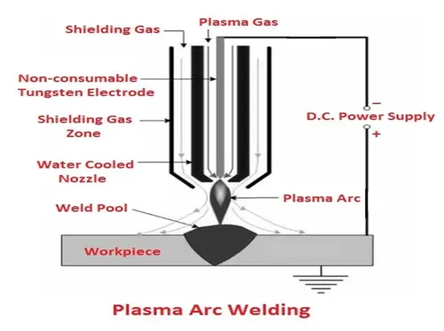
o Plasma arc welding is an arc welding process using heat produced by a compressed arc between a tungsten non-consumable electrode and another work piece (transferred arc process) or water-cooled constricting nozzle (non-transferred arc process).
o The plasma is a gaseous mixture of positive ions, electrons, and neutral gas molecules. The transferred arc process produces plasma jets of high energy density and can be utilized for high-speed welding and cutting ceramics, copper alloys, steels, aluminum, nickel alloys, and titanium alloys.
o The non-transferred arc process produces a plasma of relatively low energy density. It is used for welding and plasma spraying (coating) of various metals. Since the work piece in non-transferred plasma arc welding is not a part of the electric circuit, the plasma arc torch may move from one work piece to others without extinguishing the arc.
o The PAW works on the principle when a sufficient amount of energy is provided to any inert gas, some of its electrons are released from their nucleus but travel with it.
o After the electrons move, the atoms are converted into a hot ionized state. This is the most common condition of the substance which is known as the fourth state of matter.
o These ionized atoms have high temperatures that are used to join the two plates. This is the basic principle of PAW. This welding is a form of TIG welding in which a non-consumable tungsten electrode is used to generate the arc.
1.5)Submerged Arc Welding
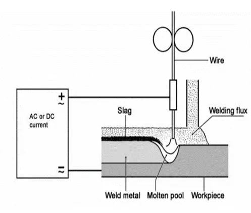
o Submerged-arc welding (SAW) is a common arc welding process that involves the formation of an arc between a continuously fed electrode and the work piece. A blanket of powdered flux generates a protective gas shield and a slag (and may also be used to add alloying elements to the weld pool) which protects the weld zone.
o A shielding gas is not required. The arc is submerged beneath the flux blanket and is not normally visible during welding. This is a well-established and extremely versatile method of welding.
o The electrode may be a solid or cored wire or a strip made from sheet or sintered material. The flux may be made by either fusing constituents to form a glassy slag (which is then crushed to form a powder) or by agglomerating the constituents using a binder and a corning process. The chemical nature and size distribution of the flux assists arc stability and determines the mechanical properties of the weld metal and the shape of the bead.
o SAW is usually operated as a mechanized process. Welding current (typically between 300 and 1000 amperes), arc voltage and travel speed all affect bead shape, depth of penetration and chemical composition of the deposited weld metal. Since the operator cannot observe the weld pool, great reliance must be placed on parameter setting and positioning of the filler wire.
o Although SAW is normally operated with a single wire using either AC or DC current, there are a number of variants including the use of two or more wires, adding chopped wire to the joint prior to welding, and the use of metal powder additions. Additional productivity may be gained by feeding a small diameter non-conducting wire into leading edge of the weld pool. This can increase deposition rates by up to 20%. These variants are used in specific situations to improve productivity through increasing deposition rates and/or travel speed. Replacing the wire with a 0.5mm thick strip, typically 60mm wide, enables the process to be used for surfacing components.
o Submerged arc welding is ideally suited to the longitudinal and circumferential butt welds required for the manufacture of line pipe and pressure vessels. Welding is normally carried out in the flat (BS EN ISO 6947 PA) position because of the high fluidity of the weld pool and molten slag and the need to maintain a flux layer. Fillet joints may also be produced, welding in either the flat or horizontal-vertical (PB) positions.
1.6)Flux Cored Arc Welding
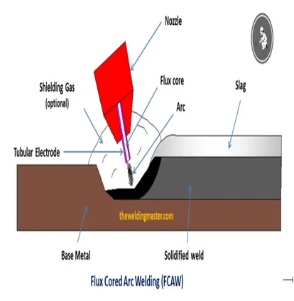
o Flux cored arc welding is another type of arc welding process that uses consumable electrode that contain flux around it. it is known as semi-automatic or automatic arc welding process. The coalescence of metal is produce by heating with an arc between continuously fed electrode and the base metals. The shielding is obtained by the flux in the electrode. Additional shield may and may not be added from an externally supplied inert gas. That is, shielding gas is supplied from an external source such as gas cylinder or a shield flux coated around the electrode which is deposited when melted.
o The flux melts together with the electrode during the welding process and shield the joint, granting the entire weld area with shielding gas. It protects the welds pool from atmosphere.
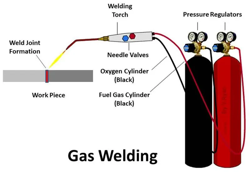
2)Oxy-Acetylene Gas Welding
o Oxy Acetylene Welding is a type of Gas Welding Process that is used to join and cut the metals. In the name Oxy Acetylene Welding, we can observe two words oxy and acetylene; the word Oxy meant Oxygen, and Acetylene is the order-less hydrocarbon gas. So, the combination of oxygen and acetylene both are used to weld the metal parts.
o The working principle of Oxy Acetylene Welding is simple in the process even though it is effective and efficient. The temperature of an Oxy Acetylene flame is about 3,500 degrees centigrade. The oxy acetylene uses the Fuel gases like Oxygen and Acetylene to weld the material.
o In this process, the welding torch produces the high-temperature flame with the help of oxygen and acetylene. Due to the high flame, the metal that needs to be weld gets weak and melted, meanwhile, a filler material is used to fill the gaps between two work pieces. As the filler is cooled, the two work pieces will be joined.
o Usage of type of Filler material depends upon the metal that needs to be weld. For example, if we want to weld the mild steel metal, then we have to use the mild steel filler. Similarly, if we want to weld the aluminum metal, then we have to use the aluminum filler.
5) What is 3-2-1 Principle?
o A fundamental concern in metalworking is locating the part to be machined, punched, bent, or stamped relative to the work platform (fixture). For example, a CNC machine tool starts its process at a specific point relative to the fixture and proceeds from there. Hence, the accuracy with which a part is machined is quite dependent on the accuracy with which it is positioned in the fixture.
o Accurate locating of not just one part, but each and every part that is loaded into the fixture is crucial. Any variation in part location on the fixture adds to the dimensional tolerance that must be assigned to the finished parts.
o Additionally, the method of supporting and securing the part in the fixture affects not only dimensional tolerances, but surface finishes as well. This is true because improper supporting or clamping can temporarily or permanently deform the part. Hence, techniques for supporting and clamping must be considered together with the method of locating in order to assure repeatability from part-to-part.
o Locating of a part to be machined is a three-step process:
o Supporting
o Locating (positioning)
o Holding (clamping)
The Locating Process: Degrees of Freedom In order to completely specify the position in space of a three-dimensional object we refer to six coordinates: 1. Translational position along the X-axis 2. Translational position along the Y-axis 3. Translational position along the Z-axis 4. Rotational position about the X-axis 5. Rotational position about the Y-axis 6. Rotational position about the Z-axis These six coordinates are known as the six degrees of freedom of a three-dimensional object. As the double-headed arrows indicate, the translational and rotational positions can vary in either direction with respect to each of the three axes. To completely prevent movement, all six degrees of freedom must be restricted. The Locating Process: 3-2-1 Method
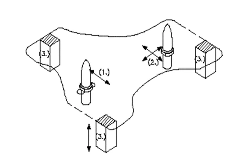
o First Plane
Geometry tells us that three points are required to define a plane. This is the "3" in 3-2-1. So, three specific points are used to define the first plane. Fewer than three points cannot define a plane, and in the real world dimensional tolerances mean that four or more points will not be coplanar. A real-world, less than ideally perfect part placed on four or more reference points will, in fact, rest on only three of the points due to its less than perfect surface. Different parts may rest on different combinations of three points, resulting in variation between finished parts. A stool can be used to illustrate this concept. A two-legged stool would certainly be unstable. A three-legged stool sits rock-solid. A four-legged stool is often found to rock. In the illustration, a three dimensional part, represented by a cube, is placed on a datum plane defined by three support points. The part’s six degrees of freedom have now been reduced to three. It can still move along the X or Y axes, and it can still be rotated about the Z axis. (The part cannot move along the Z axis because it is held against the plane by clamping force).
o Second Plane
A second plane, if it is perpendicular to the first, can be defined by two points, the "2" in 3-2-1. The part is now constrained to one degree of freedom: movement along the Y axis. (The part cannot move along the X or Z axes because it is held against the planes by clamping force.)
o Third Plane
third plane, if it is perpendicular to both of the first two planes, can be defined by one point, the "1" in 3-2-1. The part is now entirely constrained. It cannot move along or rotate about the X, Y, or Z axes. (Remember that the part is held against each of the three planes by clamping force.)
6) Define Body Coordinate System?
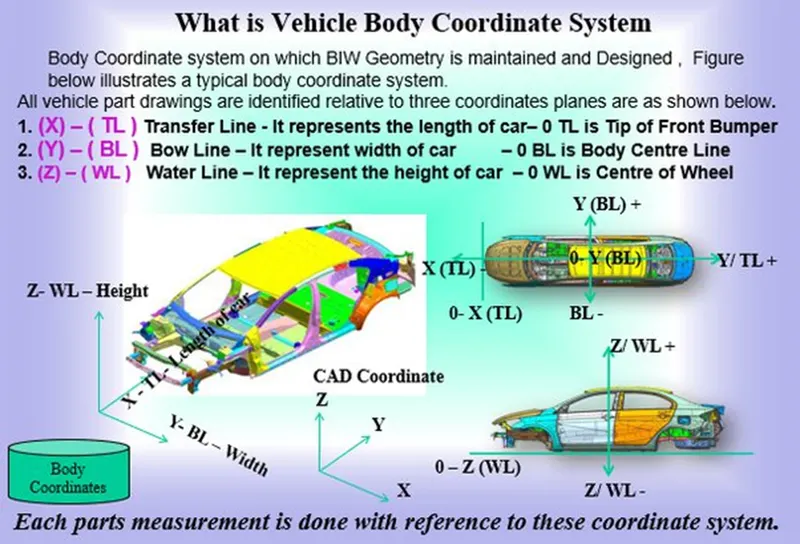
- The body co-ordinate system has been widely used in automotive industry for drawing of body parts, product and process design
- A coordinate system is a reference system consisting of a set of points, lines and surfaces, used to define the positions of points in space in either 2 or 3 dimensions.
- In general, Body Coordinate System is also called Car line or Body line
- X= Longitudinal Direction (Fore / After)
- Y= transverse Direction (Cross Car)
- Z= Vertical Direction (Up / Down)
- The Origin of the body coordinate system (OX) is defined at the center of a vehicle, it indicates “Length of Car”.
- The Coordinate System (OZ) is below its underbody indicates “Height of car”.
- The Coordinate System (OY) its starting point is the center of car body indicates “Width of Car”.
7) Elaborate Body Plane System and its essentials?
- Body Planes are the reference planes in an automobile car. These planes are used to define GD&T of all car parts in an automobile sector.
- Body planes are 3 mutually perpendicular imaginary planes. These are generally considered to be present at the driver position or sometimes at engine location or at from end of acr depending on the customer.
- The measurements from body planes to the parts are called Body line Dimensions.
- FOL : Front O Line measurement along F / A (Front Aft)
- COL: Centre O Line measurement along C / C (Cross Car)
- BOL: Body O Line measurement along U / D (Up Down)
- Body Line Dimensions are essential for the reasons listed below:
- It defines exact position of each product in vehicle with respect to a fixed origin
- Ensures flawless design for assembly
- While designing lines, all designs are carried out relative to bodyline
- It assists in easy location of different parts in a vehicle.
- Aims in creating a standardized system.
- It assists in quality checks.