Week 2 Bevel Gear Challenge
Bevel Gear Challenge-
Aim:-
To perform a grid dependency test on a bevel gear and to observe the total deformation, equivalent stress and elastic strains.
Introduction:-
Bevel gears are gears where the axes of the two shafts intersect and the tooth-bearing faces of the gears themselves are conically shaped. These gears are most often mounted on shafts that are 90 degrees apart but can be designed to work at other angles as well. The pitch surface of bevel gear is a cone.
Bevel gears are used in different drives, which can transmit power to two axles spinning at different speeds. They are also used in rotorcraft drive systems and many more applications.
1. Grid Dependency Test:-
Grid independent study or mesh independent study is a method of finding a solution that does not vary significantly even when you refine your mesh further.
When you start with a coarse mesh and solve, you may notice a difference in results as you make your mesh finer. But, there exists a limit, beyond which you won't observe any changes in the results even after you make it finer. Then we may state that we have achieved grid independence. At this point, the mesh will be fine enough to capture the most intricate details of the flow, which is why making it finer will not make any changes in the results and hence optimum and accurate results.
2. Analysis Set-up for Bevel Gear:-
I. Geometry:
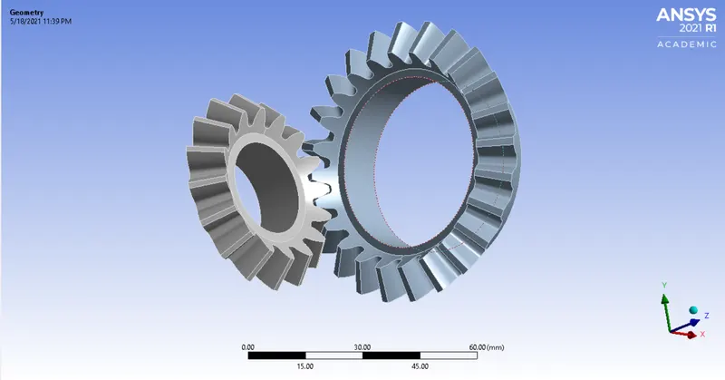
The CAD model of bevel gear is imported in ANSYS static structural environment. The Big gear has 24 faces and small gear have 16 faces. The small is called Pinion and the big gear is called Bevel gear.
II. Material:
We have performed the analysis using 'Structural Steel' as the material for the analysis of Bevel gear.
The Detailed Engineering Data of each material is as shown in the below image-
III. Connection Details:
(a) Contact Details:
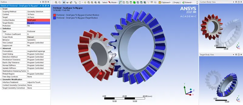
Frictional contact is given between faces of big and small gear as seen in the image below. As, the 24 faces of tooth of Big gear are selected as these surfaces which are sure come in contact, to the other 16 faces of tooth of small gear, can be neglected as contact surface is negligible.
(b) Joint Details:
Both big and small bevel gear are given revolute joint about its axis with Body-Ground type connection.
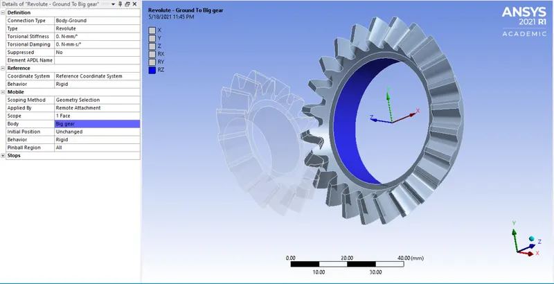
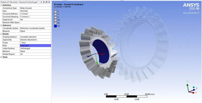
Big Gear (Joint Details) Small Gear (Joint Details)
IV. Boundary conditions and Analysis Settings:
(a) Analysis Settings:
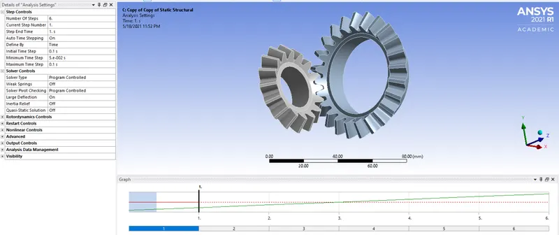
For this analysis total number of steps is set to '6' with Auto Time stepping set to ON. The initial time step is set to 0.1 seconds with minimum and maximum time step as 0.05 and 0.1 seconds respectively. In solver controls Large deflection option is set ON, so as to account for changes in stiffness due to changes in shape of the gears.
(b) Joint Details:
- Big Gear:
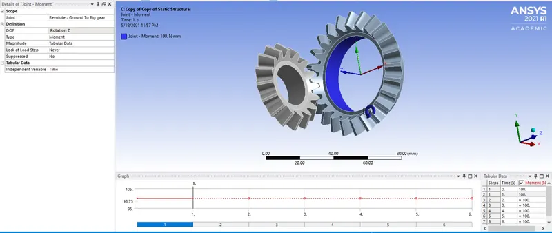
Big gear is a driving gear, hence an anticlockwise moment of 100 N.mm is applies to it.
- Small Gear:
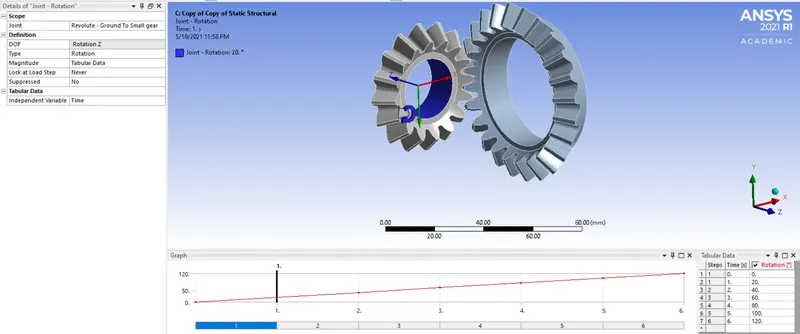
Small gear is a driven gear, hence a clockwise rotation of 120 degrees is given to it with a increment of 20 degrees in 6 steps.
V. Mesh:
Basically, we have to performed mesh of different sizes over the material of 4, 5, 6 respectively. There is a program controlled mesh of 1.75 mm for the face sizing so that the mesh could get more finer than coarse. Lastly, we are generating a fine mesh over the bevel gear which is further carried out to give desired result:
Case 1: Mesh size_6mm
Case 2: Mesh size_5mm
Case 3: Mesh size_4mm
VI. Post processing and Results:
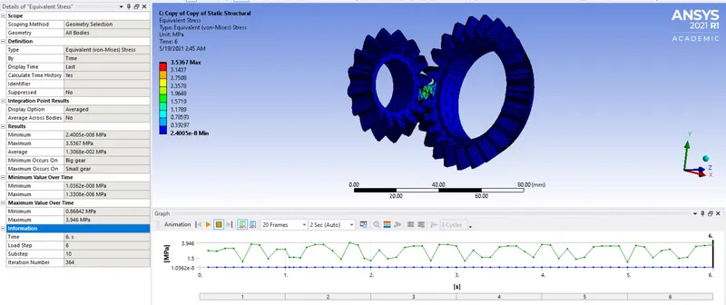
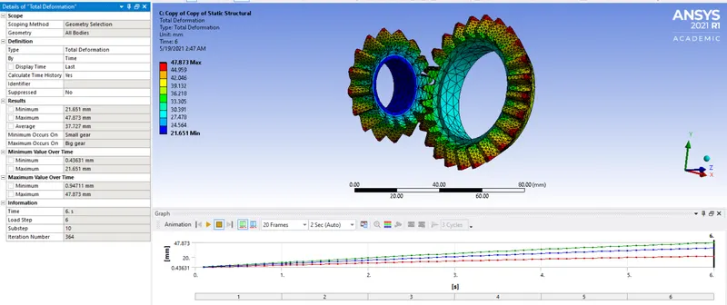
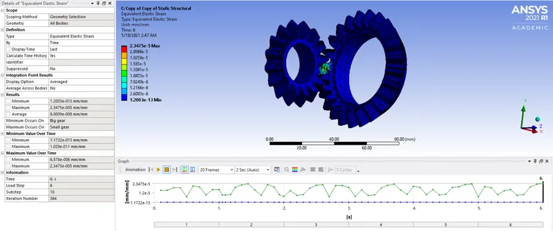
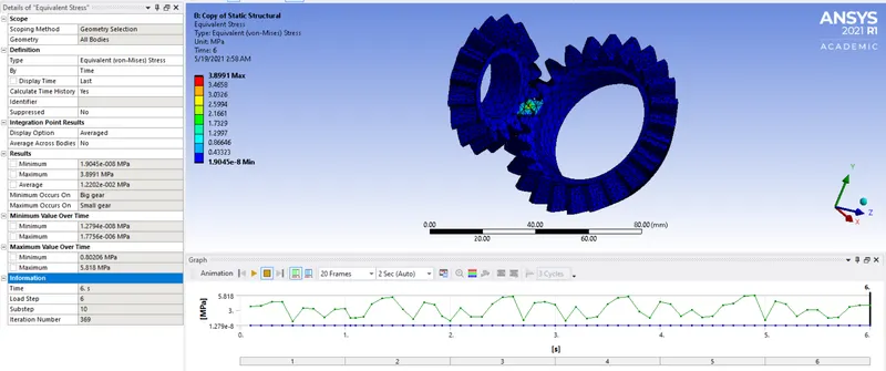
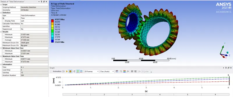
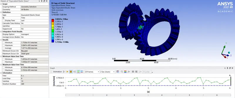
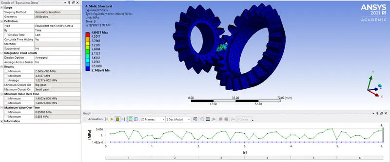
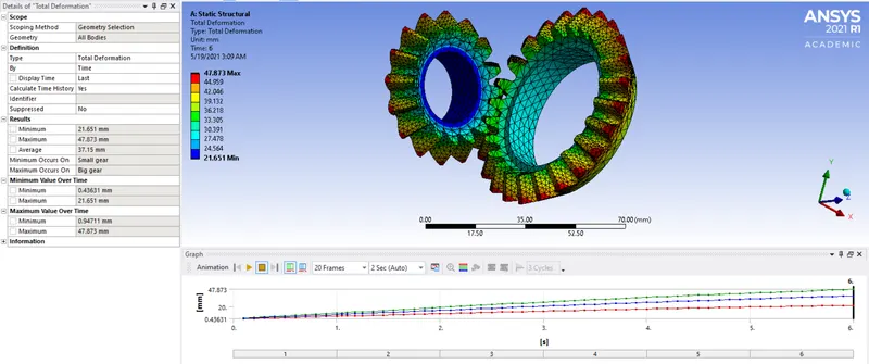
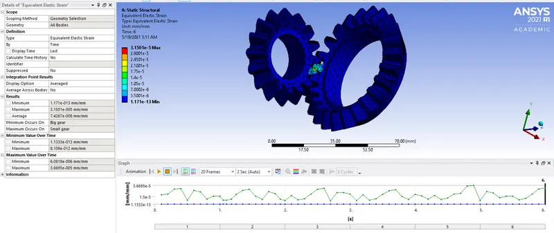
Now, bevel gear is analyzed for three different mesh sizes as 4, 5, 6 mm respectively. Then, we have to analyze the result for Total deformation, Equivalent stress and Equivalent eleastic strain . The results for each case are shown as below:
1. Case 1: Mesh size_6mm
I. Equivalent stress:
II. Total deformation:
III. Equivalent elastic strain:
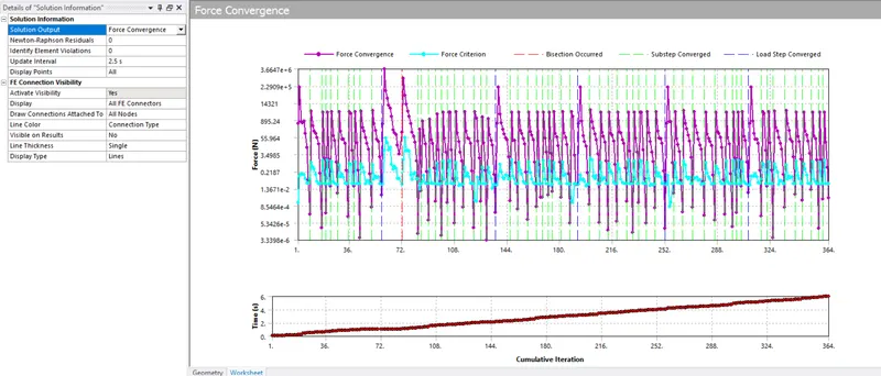
IV. Force Convergence graph:
2. Case 2: Mesh size_5mm
I. Equivalent stress:
II. Total deformation:
III. Equivalent elastic strain:
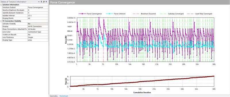
IV. Force Convergence Graph:
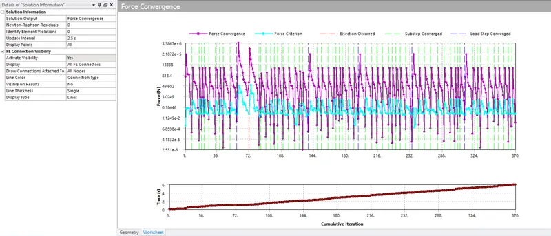
3. Case 3: Mesh size_4mm
I. Equivalent stress:
II. Total deformation:
III. Equivalent elastic strain:
IV. Force Convergence:
3. Post Processing and Summary:
|
Sr. No |
Mesh Size (mm) |
Material |
Equivalent Stress(Mpa) Max Min |
Total Deformation(mm) Max Min |
Equivalent elastic strain(mm/mm) Max Min |
|
1. |
6 |
Structural steel |
3.5367 2.400e-008 |
47.873 21.651 |
2.3475e-005 1.200e-013 |
|
2. |
5 |
Structural steel |
3.8991 1.904e-008 |
47.873 21.651 |
2.6947e-005 1.756e-013 |
|
3. |
4 |
Structural steel |
4.8427 2.342e-008 |
47.873 21.651 |
3.1501e-005 1.171e-013 |
4. Comparision:
The above table is a collective data of all the input parameters(element size in here) and the corresponding output parameters(stress, strain, total deformation). From the above table it is clear that as you decrease the element size to a lower value, the corresponding output parameters are accurate. As, observed from the table, when compared to element size 6 and 5 mm there is a gradual change in the stress and strain values. When compared to 5 and 4 mm there is not much difference and hence the optimum mesh with a grid-independent solution.
5. Conclusion:
- Total deformation is similar in all three cases.
- The values of equivalent elastic strain is decreasing when we decrease the mesh size, there is a small change in values of strain.
- Likewise, strain, equivalent stress value also changes with the mesh size.