Grid Dependency Test using Ansys Workbench.
Grid Dependency Test
’Grid Independence Test’ and 'Grid Dependency Test', ‘Mesh Refinement Test’ are synonyms and they all mean the same. While performing Finite Element Analysis, one of the most common questions is finite element mesh quality. How can one know if the mesh is good enough for the analysis? Mesh density is a significant metric used to control accuracy (element type and shape also affect accuracy). Assuming no singularities are present, a high-density mesh will produce results with high accuracy. However, if a mesh is too dense, it will require a large amount of computer memory and long run times, especially for multiple-iteration runs that are typical of nonlinear and transient analyses.
The most fundamental method of checking the mesh quality is to refine a mesh until a critical result such as Equivalent stress does not change significantly with each refinement (i.e. it converges). This is the Grid dependency test, where, analysis begins with a coarse mesh and it is refined to a finer mesh for each run until the results do not change significantly and depend on the grid size anymore. As the grid or mesh size approaches zero, the approximate solution is almost equal to the actual solution. The aim of this test is to find the optimum mesh size for the solution, where it is neither too coarse to produce inaccurate results, nor where it will consume a lot of computing effort and time.
There are different mesh refinement techniques are used which have advantages and disadvantages and some depend on the experience and technical expertise of the FEA analyst. These techniques include- Reducing the element size, Increasing the element order, Global Adaptive mesh refinement, local adaptive mesh refinement, manually adjusting the mesh, Time adaptive mesh refinement, wavelength adaptive mesh refinement, etc.
AIM:- The aim of this test is to find the optimum mesh size for the solution, where it is neither too coarse to produce inaccurate results nor where it will consume a lot of computing effort and time.
Objective:- Set up the Case of Grid Dependency to find out the best possible mesh size for Bevel Gear Analysis.
Methodology
-Called out the respective system from the Ansys Workbench for the respective Simulation (In our case it's Static Structural)
-Set the material cards for the simulation
-Import the geometry, mesh it, and set appropriate conditions for the simulation.
Procedure.
Material card
-For this assignment, we get a single set of the Bevel gear for structural Analysis. We have to set the mesh element size and the output for the stress, strain, and total deformation in the Parametric set.
by setting the Input and output parameters in the Parameter set we can check for different conditions like grid dependency. For example, by changing the element length from the coarse level to the fine level we can obtain the result without setting up the case over and over. Also, we don't have to open the model in the model editor. we can make all changes outside in the parameter set deck.
[NOTE:- the procedure for setting up the material and card is the same for all three cases, so only one case is explained here]
In Ansys Workbench there is a Static structural system available for static structural Analysis. As you can see in the image.

Engineering data option used to select or set up the Material Cards. The image below is one of the great examples that
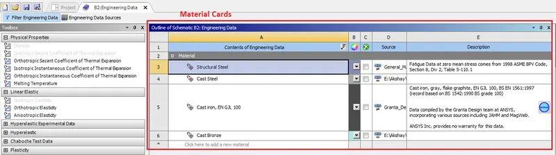
this window will open after clicking on the "Engineering Data" option and as you can see we can set the different material available in the Ansys workbench. For the materials which are not there, we can easily set the new material cards.
The second option is "geometry" from where you can create the New geometry using the "SpaceClaim" option or import the geometry in the "Desing Modeler".
For this assignment, we have geometry so I had used the import option to called out Geometry. The "Model" deck help us to mesh and Define different boundary condition over the geometries.
Contact SET-UP
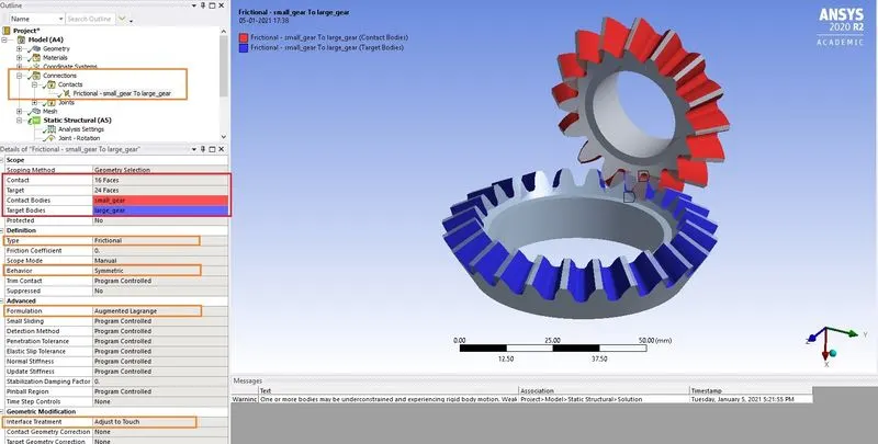
First, make contact under the connection, here the user should select the possible face that involved in the contact. Apart from that, I had defined the Type Definition- Frictional, Behavior-Symmetric, Formulation- Augmented Lagrange, Interface Treatment-Adjust to Touch.
Joint Set up (Revolute)
After contact definition it's time to add joints, Here we are using gears so we have to define the axis of rotation. Revolute joint with Body to ground contact is the best one here.
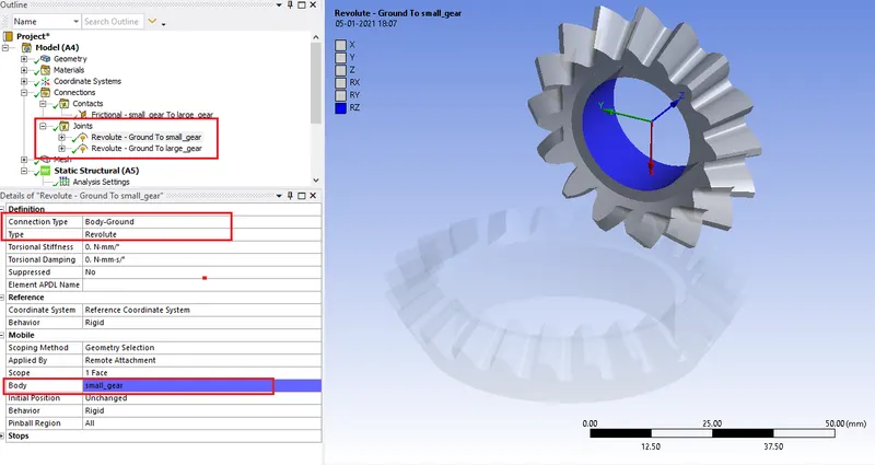
Analysis setting
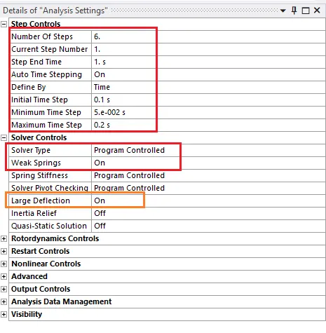
here Time step for the simulation is to be set for proper execution of the Analysis.
In the "Static-structural" Deck we have to set the boundary condition. I had to given the Rotation moment to the small gear and the moment to the large one so that it can follow the Right gear rotation movement.
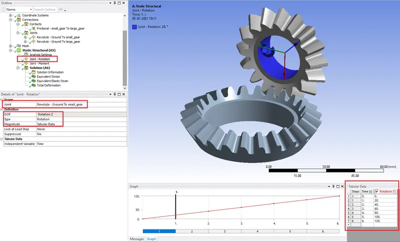
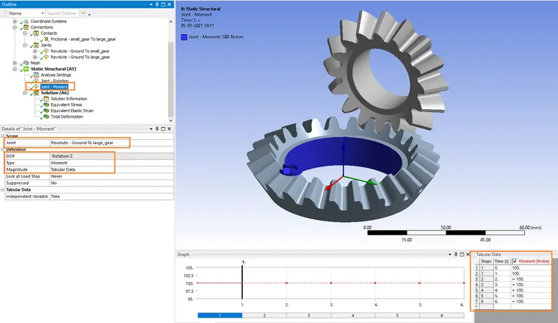
Parameter set
by setting the Input and output parameters in the Parameter set we can check for different conditions like grid dependency. For example, by changing the element length from the coarse level to the fine level we can obtain the result without setting up the case over and over. Also, we don't have to open the model in the model editor. we can make all changes outside in the parameter set deck.
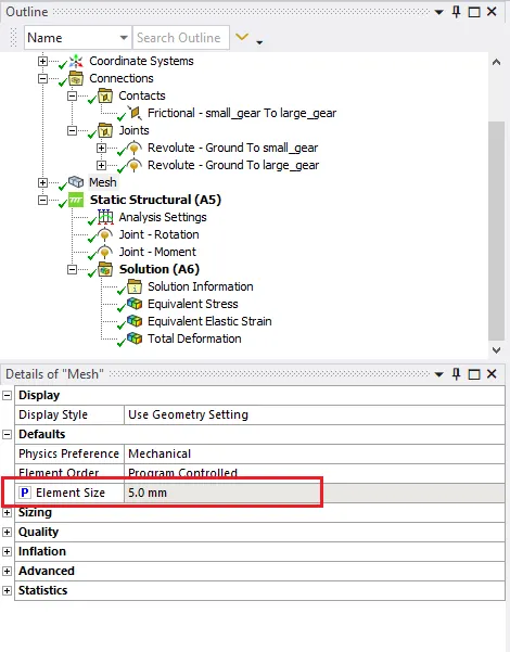
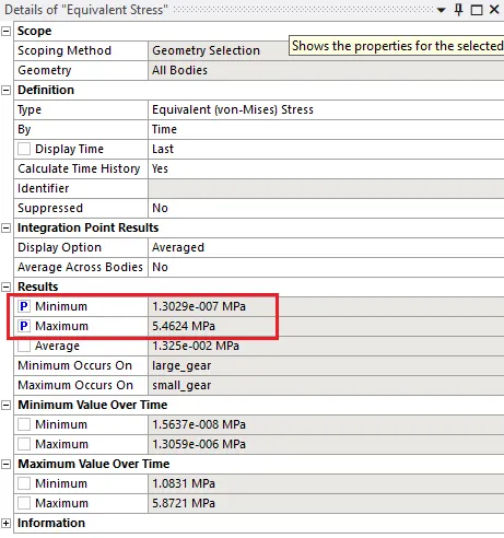
All the parameters with the "p" remark are added to the parameter set. If you want to add a parameter to the Parameter set we just have to click the adjacent check box and when you see the p symbol there it means that a specific parameter is added to the Parameter set you define.
After that, I made an output request for the required results for Von-Mises stress, Equivalent elastic strain, and Total Deformation using the previously mentioned mesh sizes (6mm, 5mm, 4mm)
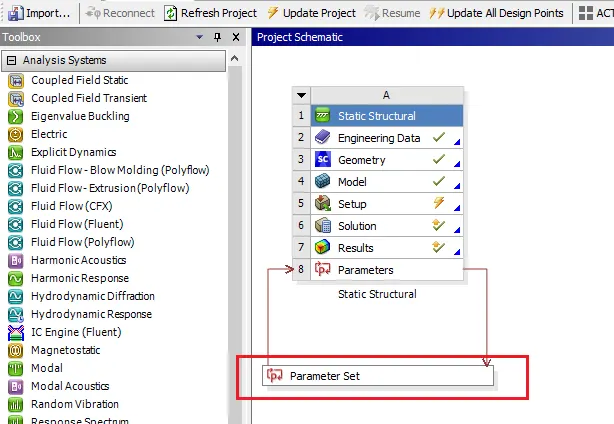
After successfully adding parameters the parameter set is getting define below the main window as per the above image.
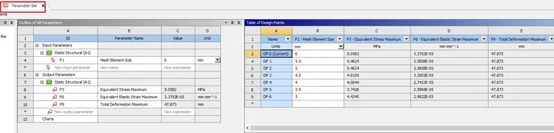
The above window shows the Parameter set module.
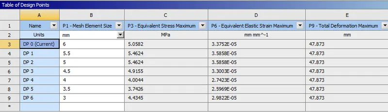
As per the observation, The total deformation in all the cases are the same that is 47.87 mm
As per the result we got as we reduced the size of the mesh and move from coarse to finer mesh we are getting more accuracy in the stress result. As per the parameter set result, the stress value we are getting with 4mm mesh is 4 Mpa and there is a sudden drop in stress value after 3.5mm mesh which indicates stress value 3.74Mpa, and again we are getting the 4.43 Mpa stress value with 3mm mesh. So the results we are getting from the 4mm and 3mm mesh are approximately the same so we can stop reducing mesh size further because with 4mm mesh size we are getting approximately the same results as we are getting with 3mm mesh size and conclude that we are found Grid dependency.
Conclusion
-The difference between 4mm and 3mm mesh size is not that significant. But there is a huge difference in stress values of 3.5mm element mesh and 4mm element mesh. And as per the definition of the Grid dependency the 4mm mesh is the optimum mesh size for the solution, where it is neither too coarse to produce inaccurate results nor too Fine to consume a lot of computing effort and time.