Week 2 Bevel Gear Challenge
AIM: - PERFORM A STATIC STRUCTURAL ANALYSIS ON THE BEVEL GEARS AND DETERMINE THE EQUIVALENT STRESS, STRAIN, AND TOTAL DEFORMATION.
Objectives: -
- Explain the GRID DEPENDENCY TEST.
- Perform a grid dependency test for the given problem.
- Compare the results for the different mesh sizes and select the best one.
Grid Dependency Test: -
A Grid Dependency test may be defined as a technique in which the results from the analysis are improved by making the mesh finer than the previously used mesh.
In FEA, the general thumb rule is finer the mesh, accurate is the result, but the problem with the fine mesh is it consumes a lot of system resources as well as time to get the accurate results.
So, it is necessary to reach an optimum mesh sizing such that the analysis results are fairly accurate and the time and resources consumed are also not too much.
This is done with the help of the Grid Dependency Test; this test helps in determining the optimum mesh size for which the results are accurate and obtained in optimum time as well.
In the present problem, the grid dependency test will be performed for three different mesh sizes which are 6 mm, 5 mm, and 4 mm. results from each case will then be compared and based on that the best size will be picked.
Steps:
First, launch the Workbench then select the Static Structural analysis.
Next, click on Engineering Data to add any material to the project environment. After that, right-click on and then click on Import to import the into the project environment.
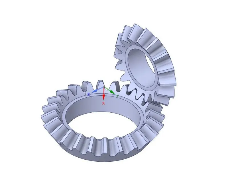
Next, double-click on to launch the SpaceClaim module. Remove the unwanted material from the and then close the SpaceClaim. The will look like this:
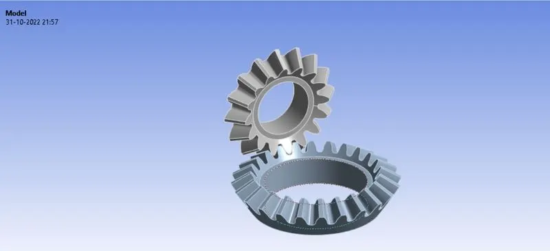
Now, double-click on Model to launch the Mechanical Module like this:
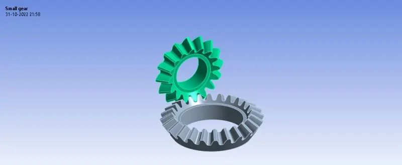
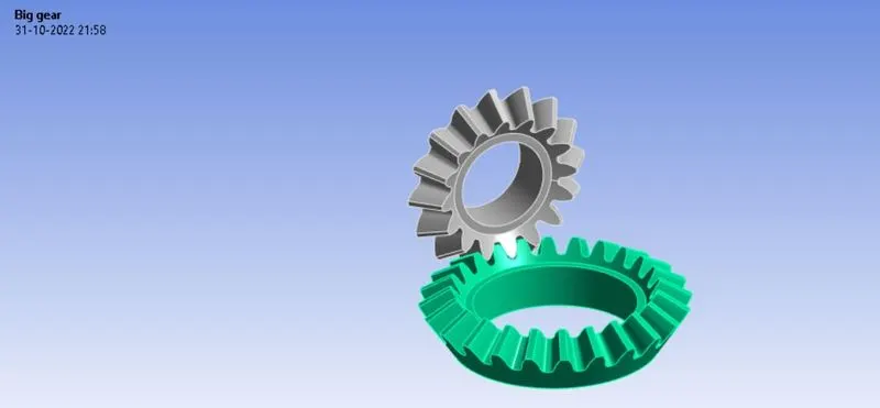
In , rename the respective gear as SMALL and BIG.
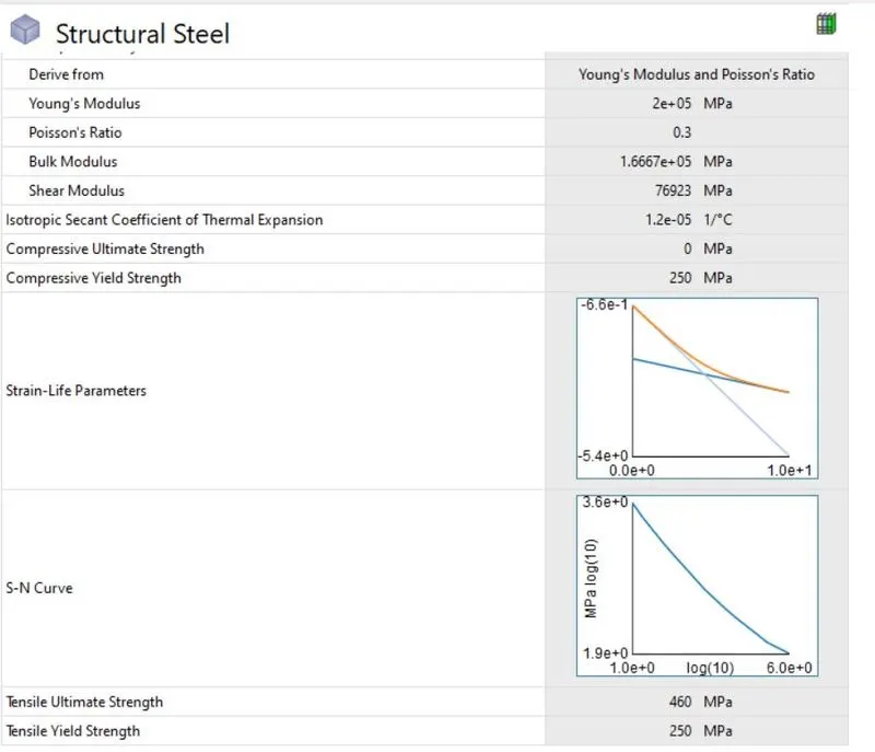
The material assigned is the default material Structural Steel. The properties table for it is shown below:
Apply Connections for both gear as fallow :-
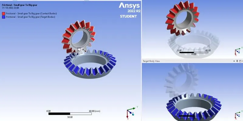
-Double-clicking on the Contacts and right-click on Contact Region and selecting the option Rename based on Definition.
-In the Scope section, click on Contact and select all the faces of the on the SMALL gear and then click Apply.
-Do the same for the Target, select the faces of the BIG gear and hit Apply.
-In the Definition section select Frictional for the Type.
-Select Symmetric for the Behaviour option.
-In the Advanced section, select the Formulation as Augmented Lagrange.
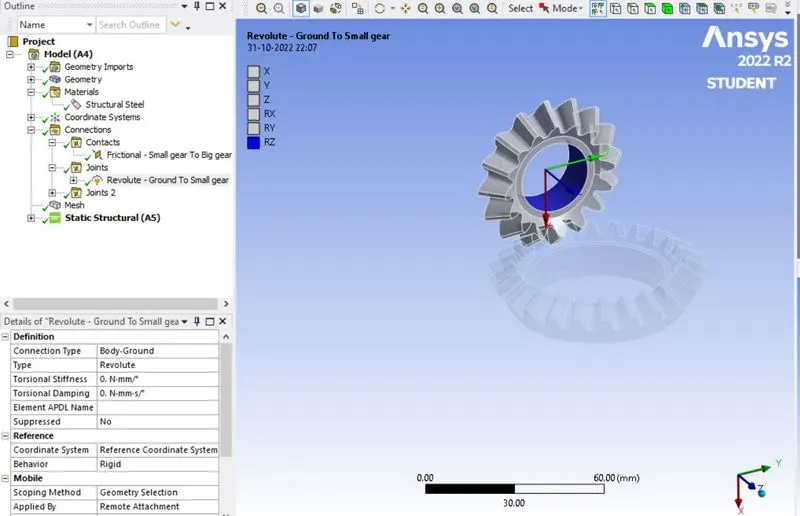
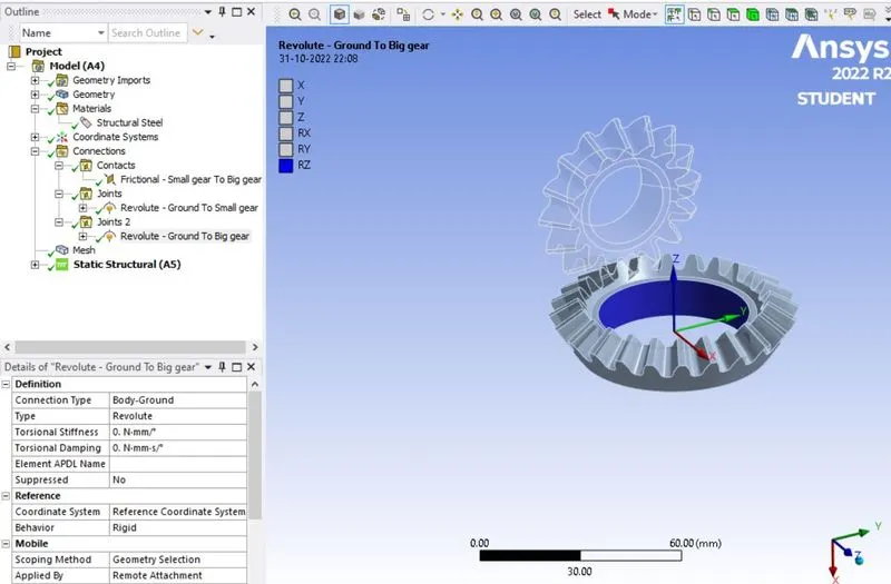
Now, the next is to create joints, this is done by right-clicking on Connections, going to Insert, and select Joint.
-In Definition section, select Body-Ground and Revolute for the Type.
-Go to the Scope section and select the inner face of the BIG gear and hit Apply.
-With this, the joint between the BIG gear and the ground is made. Follow the same process to assign the joint between the SMALL gear and the ground.
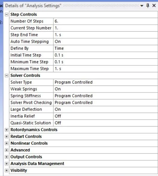
Now Set analysis setting for solver :-
- set the Number of Steps equal to 6.
Turn ON the Auto Time Stepping option.
-Select Time in the Defined By option.
-Set Initial Time Step = 0.1 sec, Minimum Time Step = 0.1 sec and Maximum Time Step = 1 sec.
-Turn the Large Deflection option ON.
After this, the next is to add the joint loads to the joints.
This is done by right-clicking on Analysis Settings, going to Insert, and selecting the Joint Load.
-Then, first, select Revolute – Ground to BIG joint. In the Definition section, select Moment for the Type option and Tabular Data for the Magnitude.
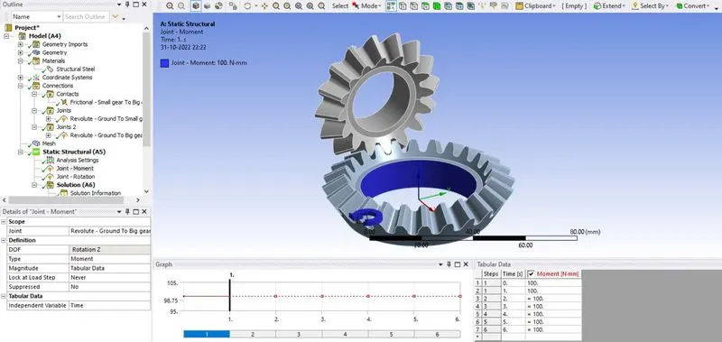
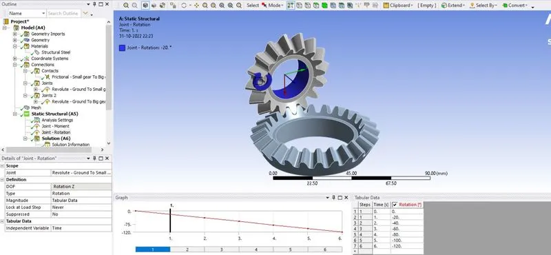
Double-click on the Joint option, select the SMALL gear joint, then go to the Reference section and click on the Coordinate System. The 3D coordinate system will then appear at the center of the SMALL gear. Change the direction of the Z-Axis to the opposite direction and hit Apply.
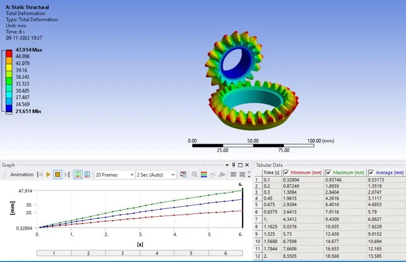
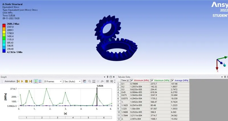
Case-1 Mesh size is 6 mm
Click on the Mesh option, and set the Element Size to 6 mm. then, in the Sizing section.
Total Deformation:-
Equivalent Stress :-
Equivalent Elastic Strain :-

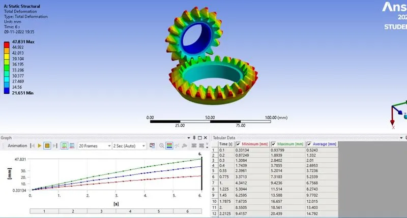
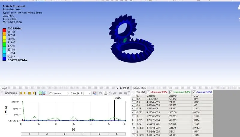
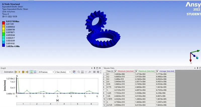
Case-2 Mesh size is 5 mm
Click on the Mesh option, and set the Element Size to 5 mm. then, in the Sizing section.
Total Deformation:-
Equivalent Stress :-
Equivalent Elastic Strain :-
Case-3 Mesh size is 4 mm
Click on the Mesh option, and set the Element Size to 4 mm. then, in the Sizing section.
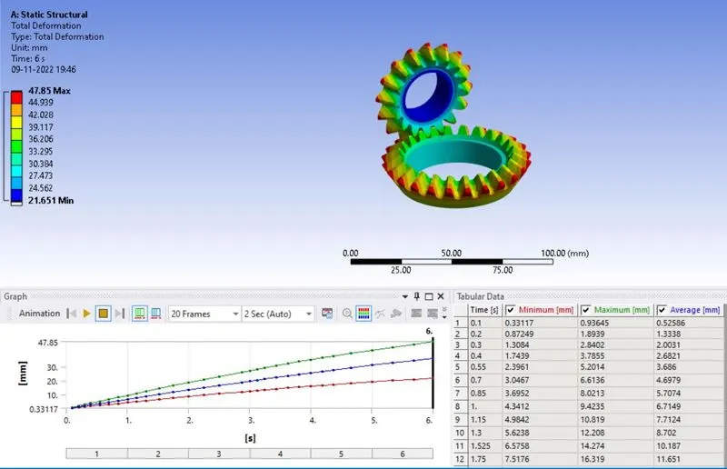
Total Deformation:-
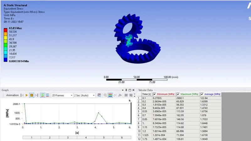
Equivalent Stress :-
Equivalent Elastic Strain :-
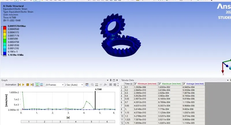
From the above, it is observed that:
The model with the mesh having an Element Size of 4 mm gave the maximum results for all the quantities among the three and the model having an element size of 5 mm gave the least results.
Thus, it can be concluded that the model having Element Size of 4 mm is the optimum size for the given Bevel Gear analysis.