Week 2 : Basic Calibration of Single cylinder SI-Engine
Aim:
- The main objective of this project is to set up and run a model of a single cylinder 4-stroke SI Engine at 1800 rpm in GT-Suite
- To run the same model at 3600 rpm and increase the power-output by 10%
Theory:
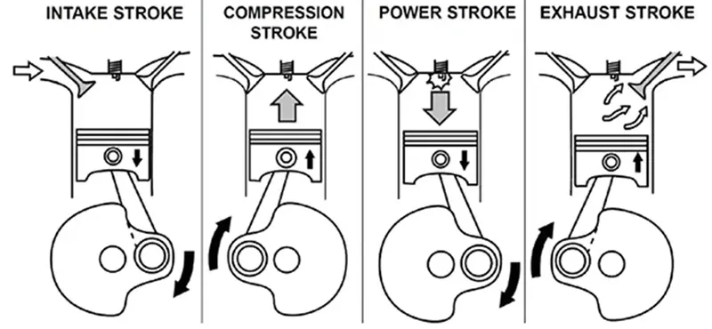
An internal combustion engine (ICE) is a heat engine in which the combustion of a fuel occurs with an oxidizer (usually air) in a combustion chamber that is an integral part of the working fluid flow circuit. In an internal combustion engine, the expansion of the high-temperature and high-pressure gases produced by combustion applies direct force to some component of the engine. The force is applied typically to pistons, turbine blades, a rotor, or a nozzle. This force moves the component over a distance, transforming chemical energy into useful work.
Intake stroke:
- Piston moves down the cylinder bore from top dead center (TDC) to bottom dead center (BDC)
- Intake valve is open, the exhaust valve is closed
- Downward piston motion creates a vacuum (negative air pressure) that draws that air/fuel mixture into the engine via the open intake valve
Compression stroke:
- Piston moves up the cylinder bore from bottom dead center to top dead center
- Both the intake and exhaust valves are closed
- Upward piston motion compresses air/fuel mixture in the combustion chamber
Power stroke:
- At the end of the compression (previous) stroke, the spark plug fires and ignites the compressed air/fuel mixture. This ignition/explosion forces the piston back down the cylinder bore and rotates the crankshaft, propelling the vehicle forward.
- Piston moves down the cylinder bore from top dead center to bottom dead center
- Both the intake and exhaust valve are closed
Exhaust stroke:
- Piston moves up the cylinder bore from bottom dead center to top dead center. The momentum caused by the power stroke is what continues the crankshaft movement and the other 3 strokes consecutively.
- Intake valve is closed, the exhaust valve is open
- This final stroke forces the spent gasses/exhaust out of the cylinder. The cycle in now complete and the piston is ready to begin the intake stroke.
Air flow rate:
It is the amount of air that is entering the engine and it is important because it decides how the fuel combustion takes place. A low air flow produces incomplete combustion leading to CO emissions whereas a higher air flow leads to NOx emissions. Therefore, an air flow close to stoichiometry is desired.
Brake mean effective pressure:
It is the ratio of gross work-done per cycle to the volume displaced per cycle. It provides a valuable measure of the engine performance which is independent of the engine displacement.
Brake specific fuel consumption:
It is the amount of fuel consumed per unit power produced in a cycle. Low values of BFSC are desirable
In-cylinder pressure:
It is the maximum pressure that is developed inside the engine during a single cycle. It provides a measure of the work that can be extracted from the engine
Model setup:
Then model is setup from scratch by following the in-built tutorial on single cylinder SI engine. The following figure shows the final structure of the model.
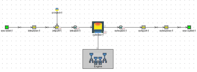
This model uses the Woschni GT model for heat – transfer. This model closely emulates the classical Woschni correlation without swirl. A wiebe function is used here to impose the combustion burn rate. In this model, the fuel is injected depends on the specified air-fuel ratio and the air-flow rate in the inlet-runner (in runner). The in-built indolence-combust model was used for fuel. The timing of the fuel injection is controlled by the cylinder. The specifications of the engine used in this model is summarized in table below.
Case 1:
Simulation of the single cylinder engine at the 1800 rpm:
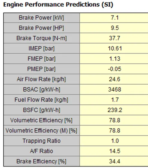
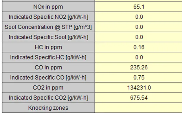
Brake power = 7.1 kW.
BSFC = 239.2g/kw-h.
Case 2:
Engine at 3600rpm.
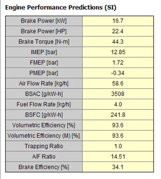
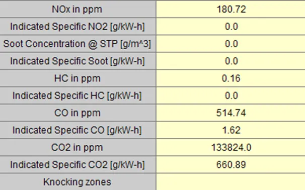
Brake power = 16.7 kW.
BSFC = 241.8 g/kw-h.
Case 3:
The formula for calculating the brake power of an engine is shown in the below plot
Power and mechanical efficiency:
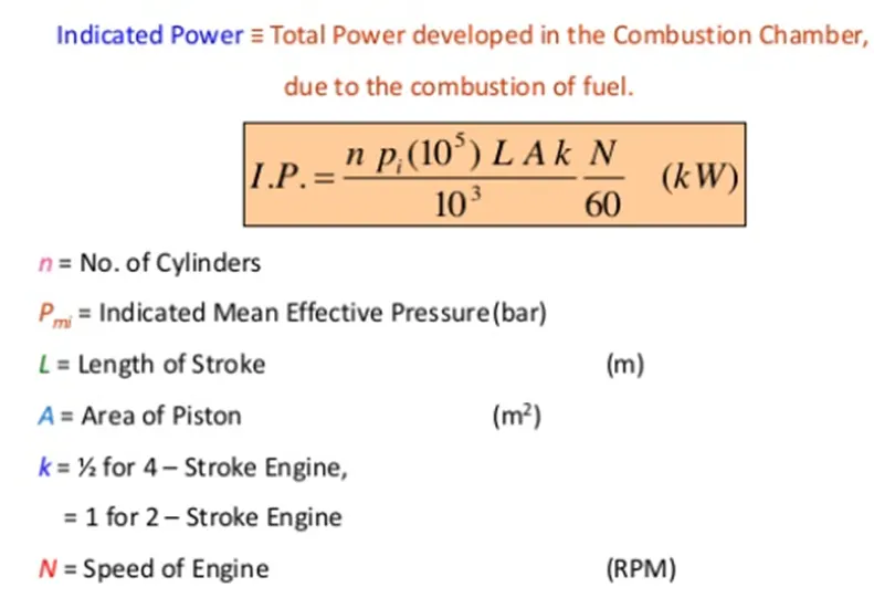
To increase the power output at 3600rpm. From the above equation, we infer that power output is dependent on engine geometry which in turn is dependent on engine geometry parameters such as bore, stroke and connecting rod length. Also it is dependent on the mean effective pressure.
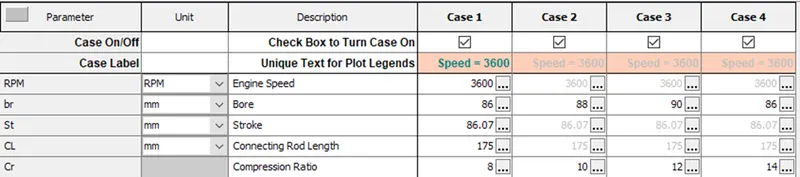
Case 1: the default case setup at 3600rpm.
Case 2: bore dimension is changed from 86mm to 90mm.
Case 3: stroke length is changed from 86.07mm to 96mm.
Case 4: compression ratio from 8 to 14.
Case setup:
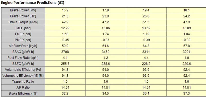
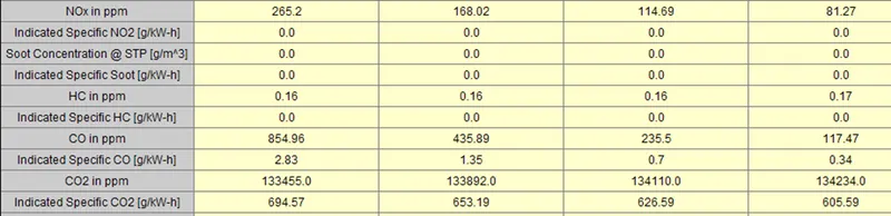
Case 1: brake power = 15.9KW
Case 2: brake power = 17.8KW
Case 3: brake power = 19.4KW
Case 4: brake power = 18.1KW
Conclusion:
In this project the 1D model of a single cylinder 4-stroke SI engine was successfully developed in GT-Suite. The model was then used to study the effect of different parameters in increasing the brake power of the engine at 3600 rpm.