Week 2 Air standard Cycle
OBJECTIVE: To create a PV diagram for the given Air Standard Cycle (Otto Cycle).
PROBLEM STATEMENT:
- Find required parameters at each state of the otto cycle, such as pressure, temperature, volume.
- Find the thermal efficiency of the Otto cycle.
SOLUTION PROCEDURE:
- At first, with the help of geometric input parameters and four state parameters, the otto cycle plot ( PV diagram) is generated. But the generated plot shows a linear variation in the compression and expansion process, which violates the adiabatic relation between pressure and volume.
- So, to resolve the above issue and trace the volume in the plot of the otto cycle, we are using an equation that relates the crank angle (Ɵ) and volume of the combustion chamber (V).
- Equation 1:

- We define a function ENGINE KINEMATICS and use the above relation to calculate the volume of compression and volume of expansion and corresponding pressures with the help of geometric input parameters such as bore, stroke, compression ratio, and length of connecting rod, Crankpin radius.
- The help of the above equation 1 and the thermodynamic relations used in otto cycle calculations (such as ideal gas equation and adiabatic relations…etc.) are used to calculate all the state properties.
- At last efficiency of the Otto cycle was calculated by using the stated formula.
-

- With the help of the plot command, an otto cycle plot was generated, which clearly depicts the working of the Otto cycle.
-
CODE WITH EXPLANATION:
-
import math
import matplotlib.pyplot as plt

# Defining the function ENGINE_KINEMATICS.

def ENGINE_KINEMATICS(d,l,starting_crank,ending_crank,r_c,c_r):
	v_s=(math.pi/4)*pow(d,2)*l    # CALCULATING SWEPT VOLUME.
	v_c=v_s/(r_c-1)               # CALCULATING CLEARANCE VOLUME.
	n_theta=50                    # UPPER LIMIT OF LOOP.
	theta=[]                      # CREATING AN EMPTY ARRAY OF THETA (i.e CRANK ANGLE).
	sc=math.radians(starting_crank) #  DEFINING STARTING CRANK ANGLE IN RADIANS.
	ec=math.radians(ending_crank)   # DEFINING ENDING CRANK ANGLE IN RADIANS.
	dtheta=(ec-sc)/(n_theta-1)     # INCREMENTING EACH VALUE OF THETA with the help of above parameters (i.e n_theta;sc;ec).
	a=l/2                          # DEFINING  CRANK PIN RADIUS (= STROKE/2)
	R=c_r/a                      # DEFINING  A CONSTANT i.e R (= LENGTH OF CONNECTING ROD/a)
	V=[]                           # CREATING AN EMPTY ARRAY OF VOLUME.
	for i in range(0,n_theta):
		# CALCULATING EACH AND EVERY VALUE OF THETA.
		theta=sc+i*(dtheta)
		# CALCULATING THE TERMS IN THE EQUATION WHICH RELATES CRANK ANGLE (THETA) AND VOLUME OF THE COMBUSTION CHAMBER (V).
		# THIS EQUATION GIVES VOLUME TRACE WHICH IS NEEDED FOR PLOTTING OF OTTO CYCLE.
		term1=0.5*(r_c-1)
		term2=R+1-(math.cos(theta))
		term3=pow(R,2)-pow(math.sin(theta),2)
		term3=pow(term3,0.5)
		# APPENDING THE ABOVE CALCULATION TO THE CREATED EMPTY ARRAY (V=[])
		V.append((1+term1*(term2-term3))*v_c)
	return V   # RETURNING THE VALUES.

# INPUT PARAMETERS
d=0.25     # DEFINING DIAMETER OF BORE (in M).
l=0.375    # DEFINING STROKE LENGTH (in M).
gamma=1.4  # DEFINING SPECIFIC HEAT RATIO OF AIR.
r=5        # DEFINING COMPRESSION RATIO.
v_s=(math.pi/4)*pow(d,2)*l
v_c=v_s/(r-1)

#  CALCULATING STATE 1 VARIABLES (P1,V1,T1)
V1=v_s+v_c
print(V1)
P1=101325  # (pressure in pascals)
T1=288     #( Temperature in kelvin)

#  CALCULATING STATE 2 VARIABLES (P2,V2,T2)
V2=v_c
# P1*V1^gamma=P2*V2^gamma

P2=P1*pow(r,gamma)
print(P2)

Constant=(P1*V1)/T1
T2=(P2*V2)/Constant
print(T2)

# CALCULATING STATE 3 VARIABLES (P3, V3, T3)
V3=V2
P3=45*101325  # GIVING VALUE TO PRESSURE AT STATE 3 ( in Pa)
# Calculating T3

T3=(P3/P1)*T1
print(T3)

 #  CALCULATING STATE 4 VARIABLES (P4,V4,T4)
V4=V1
 # Calculating P4
P4=(P3)*pow((V3/V4),gamma)
print(P4)

 # Calculating T4
T4=(P4/P1)*T1
print(T4)

# GIVING INPUT VALUES TO THE ABOVE DEFINED FUNCTION i.e ENGINE KINEMATICS ( i.e for compression stroke)
ENGINE_KINEMATICS(0.25,0.375,0,180,5,15)

# CALCULATING THE ARRAY OF V_COMPRESSION.
V_compression=ENGINE_KINEMATICS(0.25,0.375,0,180,5,15)

 # CREATING AN EMPTY ARRAY OF P_COMPRESSION AND CALCULATING THE VALUES IN THE ARRAY OF P_COMPRESSION (using the values of V_compression).
P_compression=[]
Const=P1*pow(V1,1.4)

for v in V_compression:
 	P_compression.append(Const/pow(v,gamma)) # APPENDING EACH AND EVERY ABOVE CALCULATED VALUE TO THE EMPTY ARRAY OF P_COMPRESSION.
print(P_compression)

# GIVING INPUT VALUES TO THE ABOVE DEFINED FUNCTION, i.e., ENGINE KINEMATICS (i.e., for expansion stroke)
ENGINE_KINEMATICS(0.25,0.375,0,180,5,15)

# CALCULATING THE ARRAY OF V_COMPRESSION.
V_expansion=ENGINE_KINEMATICS(0.25,0.375,180,0,5,15)


# CREATING AN EMPTY ARRAY OF P_EXPANSION AND CALCULATING THE VALUES IN THE ARRAY OF P_EXPANSION (using the values of V_expansion).
P_expansion=[]
rhs=P3*pow(V3,1.4)

for v in V_expansion:
	P_expansion.append(rhs/pow(v,gamma))  # APPENDING EACH AND EVERY ABOVE CALCULATED VALUE TO THE EMPTY ARRAY OF P_EXPANSION.
print(P_expansion)

# Calculating Efficiency (E)
E1=pow(r,(gamma-1))
E=1-(1/E1)
print(E)

# PLOTTING THE  AIR STANDARD CYCLE (OTTO CYCLE) FOR ABOVE OBTAINED RESULTS.
plt.plot([V2,V3],[P2,P3])
plt.plot(V_compression,P_compression)
plt.plot(V_expansion,P_expansion)
plt.plot([V4,V1],[P4,P1])

# LABELLING X-AXIS AND Y-AXIS
plt.xlabel('VOLUME')
plt.ylabel('PRESSURE')
plt.show()
RESULTS AND DISCUSSIONS:
-
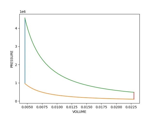
The Generated plot (PV diagram) of the Otto cycle is:
-
As we know, the Otto cycle is a Constant volume heat addition and Constant volume heat rejection process. It is clearly seen from the above plot, which is highlighted with blue color (HEAT ADDITION) and red color (HEAT REJECTION).
Orange curve represents Reversible Adiabatic compression from the state (1 to 2). And the Green curve represents Reversible Adiabatic expansion from the state (3 to 4).
The above variations are obtained with the help of the equation that relates between crank angle and volume inside the combustion chamber. (i.e., equation1).
The efficiency of the Otto cycle is 47.469 %. (The above-mentioned formulae obtain it).
The maximum temperature attained is 1362 kelvin. (For the given input values).