Week -2
1.
Aim:- Simulink model of doorbell using solenoidal block.
Condition:- Switch is closed for 2 second and released.
Block used:-
- Pulse generator.
- switch.
- Battery.
- Solenoid.
- Scope.
- Sover configuration.
- Electrical Referenc.
- Mechanical Translational Referenc.
- Ideal Translational motion sensor.
Model:-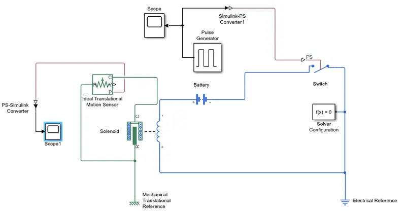
Model explained:-
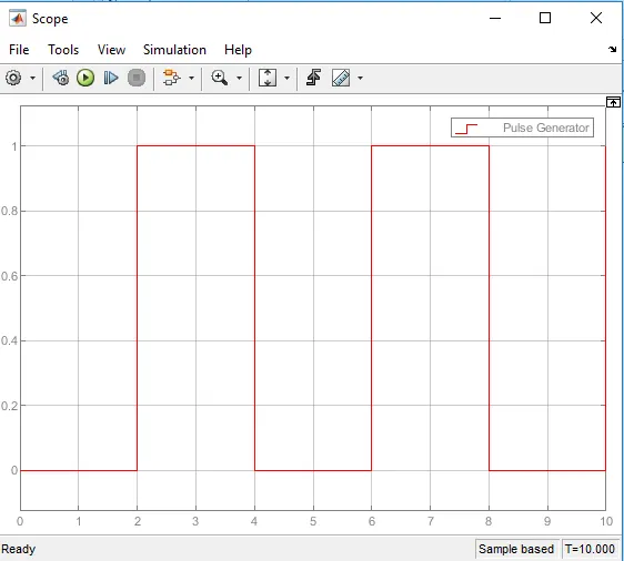
- A pulse generator is given input for bell is engage for 2 second and released.
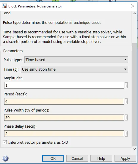
- The signal from pulse generator converted using a simulink-PS converter and is given as the input to the switch.
- A solenoid and battery is connected to it.
- The switch is also connected to the circuit.
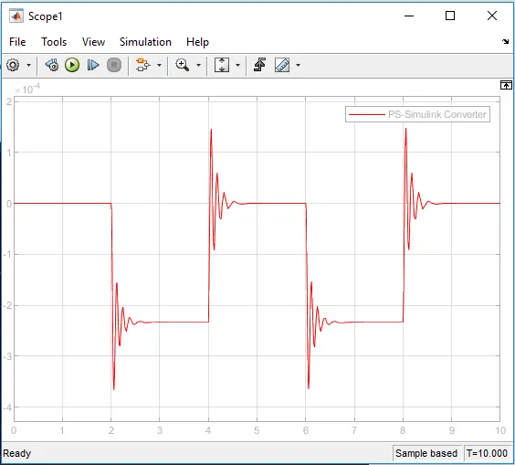
- The position of solenoid plunger is measured using ideal translational motion sensor.
- Mechanical and electrical refrences are connected to the respective circuit.
- Output from ideal translational motion sensor is converted using PS-simulink converter and is given to scope to show result.
- A scope is also connected to the input to see the input signal behaviour.
Input signal:
Output signal:
2. Use a thermistor to sense the temperature of a heater & turn on or turn off the fan.
Aim:-
A simulink model of thermistor to sense the temperature of a heater &turn on or turn off the fan.
Condition:-
Temperature source: 20C from 0 to 10 seconds, 23C from 30 to 50 seconds.
Fan condition: ON if the temperature above 25C, OFF otherwise.
Blocks used:-
- Signal builder
- Controlled temperature source
- Thermistor
- Resistor
- Voltage sensor
- Voltage source
- Switch
- Scope
- Display
- PS-simulink converter
- Simulink-PS converter
- Solver configuration
Simulink model:-
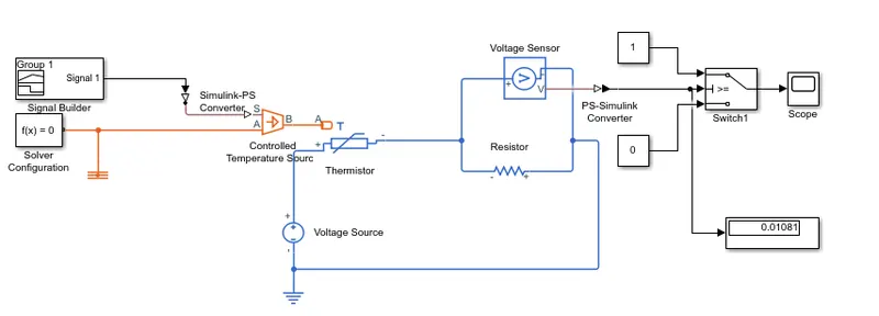
Explanation of model:-
- Input signal is given to signal builder and Connected with thermistor through controlled temperature source. The inputs signal is given to the thermistor.
- In signal builder temperature in kelvin is given in the form of signal.
- Thermistor is connected to resistor connected in the current flowing direction.
- Across resistor voltage sensor is connected.
- Voltage source is connected across thermistor and resistor and electrical reference connected to it.
- Output terminal of voltage sensor is connected to switch in which switch parameter conditions are fan is ON when temperature is above 25C below that fan will be OFF.
- It further connected to scope to show the result.
Output:-
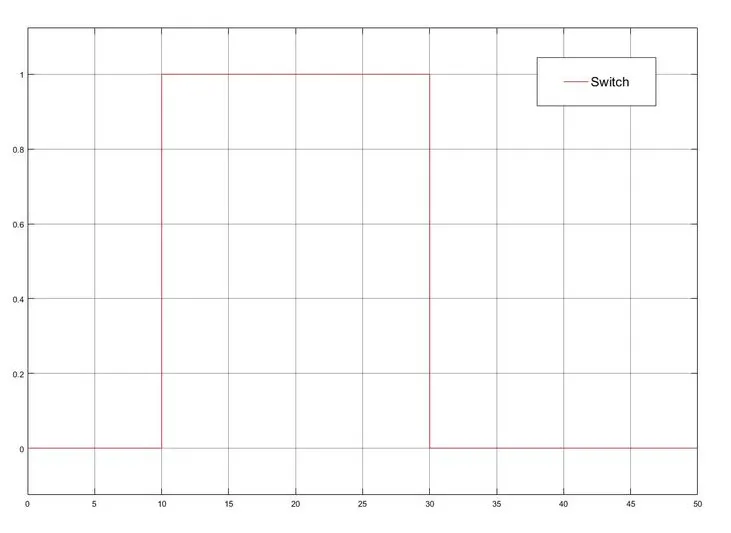
- For 0 to 10 second fan is in OFF condition because temperature is 293K.
- For 10 to 30 second fan will be ON bacause temperature is 300K.
- For 30 to 50second fan will be OFF bacause temperature is 296K.