Week -2
Objective:
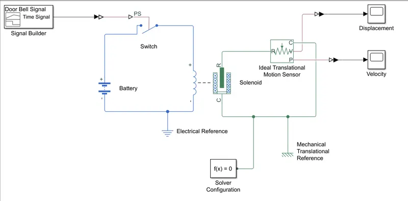
- The main objective is to create the Simulink model for Doorbell and to create a situation where the switch is closed for 2 seconds and then released.
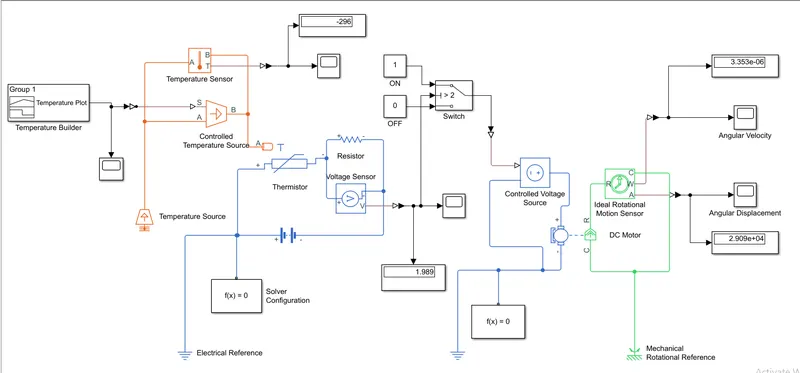
- To create the Thermistor to sense the heater temperature to turn on/off the fan under the conditions as follows:
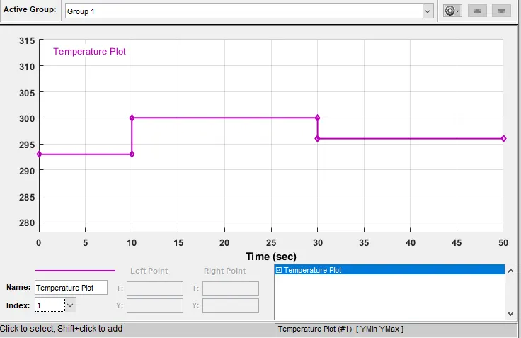
- Temperature source: 20 °C from 0 to 10 seconds, 27 °C from 10 to 30 seconds, 23 °C from 30 to 50 seconds
- Fan conditions: ON if the temperature above 25 °C, OFF otherwise.
Theory:
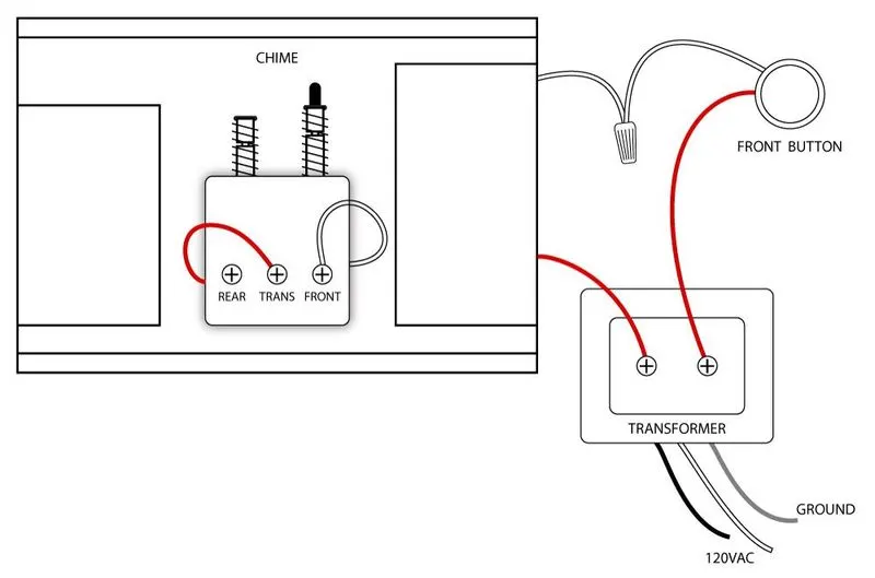
Door Bell:
A doorbell is a signaling device typically placed near a door to a building's entrance. When a visitor presses a button the bell rings inside the building, alerting the occupant to the presence of the visitor. Although the first doorbells were mechanical, activated by pulling a cord connected to a bell, modern doorbells are electric, operated by a pushbutton switch. Modern doorbells often incorporate intercoms and miniature video cameras to increase security.
Solenoid:
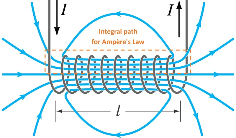
- A solenoid is a device comprised of a coil of wire, housing, and a moveable plunger (armature).
- When an electrical current is introduced, a magnetic field forms around the coil which draws the plunger in.
- A solenoid converts electrical energy into mechanical work.
- The coil is made of many turns of tightly wound copper wire. When an electrical current flows through this wire, a strong magnetic field/flux is created.
- The housing, usually made of iron or steel, surrounds the coil concentrating the magnetic field generated by the coil.
- The plunger is attracted to the stop through the concentration of the magnetic field providing the mechanical force to do work.
Thermistor:
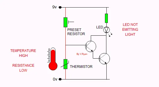
A Thermistor is a resistance thermometer or a resistor whose resistance is dependent on temperature. There are two types of thermistors
- Negative Temperature Coefficient (NTC)
- Positive Temperature Coefficient (PTC)
When the temperature increases, resistance decreases. Conversely, when temperature decreases, resistance increases it is called an NTC Thermistor.
When temperature increases, the resistance increases, and when temperature decreases, resistance decreases it is called a PTC Thermistor.
Procedure:
- Doorbell Model:
- The Doorbell signal needs to be in a way that it should ring for 2 secs and then it should
- A signal builder is used to create a graph for a 2-sec rise and then a 2-second drop.
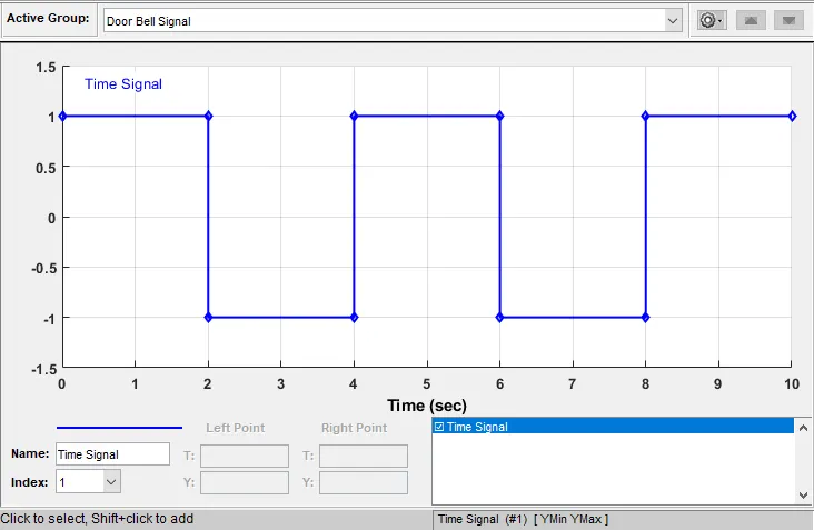
- We need to attach the signal builder to Simulink to PS converter and then to a switch that is attached to a battery.
- The battery is used to have an electrical reference that works as earthing.
- The output of the switch is connected to the solenoid and the other end of the solenoid is connected to the battery creating a proper input electrical circuit.
- The solenoid has a coil and a rod and the rod is displaced to change current to the coil.
- The R and C on the solenoid block represent the plunger and the reference point respectively.
- To measure the displacement for the solenoid plunger, an ideal translational motion sensor is connected to the solenoid (R to R and C to C ports of the sensors).
- Now, attach the circuit with Mechanical Translational Reference as a reference point for the movement of the plunger and measure the actual displacement.
- The solver configuration block is attached to the circuit to provide the guide to the ode solver to solve the circuit.
- Run the code. And click on the scope attached to check the graphs.
- Thermistor Model:
- The circuit requires a heating source, a thermistor, a signal builder, resistor, DC motor, and some switches and voltage regulator.
- The Circuit starts with a signal builder in which a signal is created with the temperatures as given above ( 0 to 10 secs – 20 °C, 10 to 30 secs - 27 °C, 30 to 50 secs - 23 °C)
- Attach the signal builder to Simulink- PS converter which is connected to Controlled Temperature Source at S-port.
- The Controlled Temperature source temperature is checked by using a temperature sensor.
- The A and B ports of the Controlled Temperature Source are connected to Thermal Reference and Thermistor.
- The Positive end of the thermistor is connected to the positive end of the battery and the negative end of the thermistor is connected to the positive end to the resistor and the negative end of the resistor is connected to the negative end of the battery.
- A Voltage Sensor is placed between the Resistor (positive to the positive side and negative to the negative side)
- A solver configuration block and Electrical Reference are used to solve the ODE equations and to give earthing respectively.
- The physical port V from the Voltage sensor is connected to a PS to Simulink Converter which is connected to a Switch.
- The Switch is connected to constants 1 and 0 which represent the ON and OFF of a switch.
- The output of the switch is connected to the Controlled Voltage Source negative end.
- The Positive end of the Controlled Voltage Source is connected to a DC source and negative to negative.
- The R port of the DC motor is attached to the R port of the Ideal Rotational Motion Sensor. The C port is connected to the C port in the DC motor with a Mechanical Rotational Reference.
- W and A are the physical ports for Velocity and Angular Displacement which are attached to the scope and display to check the graph and the final values.
Result:
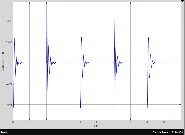
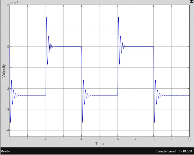
The Doorbell is created such that it will ring for 2 seconds then it will stop.
Displacement Vs Time:
Velocity Vs Time:
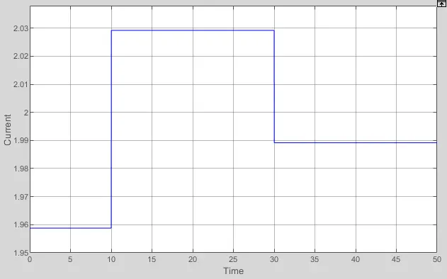
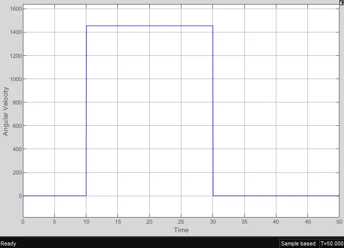
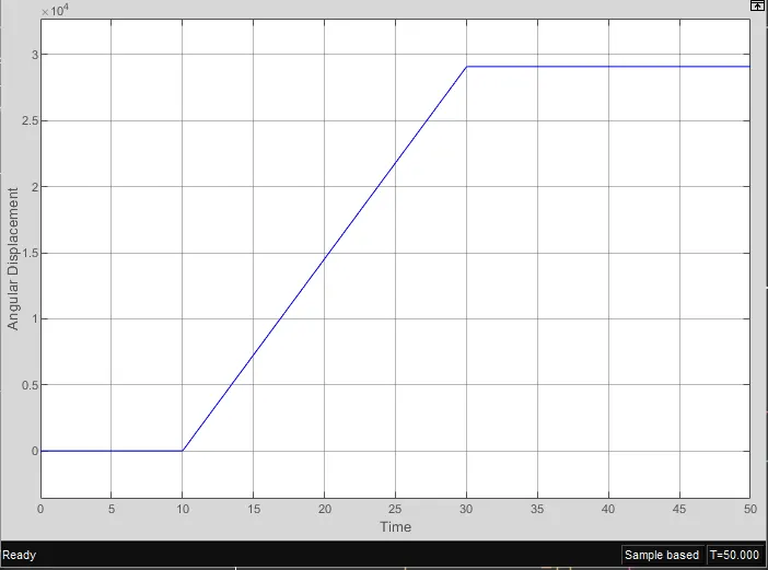
The thermistor connections are created as per given temperature ranges.
Current Vs Time:
Angular Velocity Vs Time:
Angular Displacement Vs Time:
Tools used:
- Signal Builder:
- Signal Builder as the name suggests it create the signals as per the user inputs.
- Ideal Translational Motion Sensor:
- The block represents an ideal mechanical translational motion sensor, that is, a device that converts an across variable measured between two mechanical translational nodes into a control signal proportional to velocity and position. The sensor is ideal since it does not account for inertia, friction, delays, energy consumption, and so on.
- Connections R and C are mechanical translational conserving ports and connections V and P are physical signal output ports for velocity and position, respectively. The block positive direction is from port R to port C.
- Mechanical Translational Reference:
- The block represents a mechanical translational reference point, that is, a frame or ground. Use it to connect mechanical translational ports that are rigidly affixed to the frame (ground)
- Electrical Reference:
- Electrical reference port. A model must contain at least one electrical reference port (electrical ground).
- Temperature Sensor:
- The block measures temperature in a thermal network. There is no heat flow through the sensor. The physical signal port T reports the temperature difference across the sensor. The measurement is positive when the temperature at port A is greater than the temperature at port B.
- Controlled Temperature Source:
- This block represents an ideal energy source in a thermal network that can maintain a controlled temperature difference regardless of the heat flow rate. The temperature difference is set by the physical signal port S. A positive temperature difference causes the temperature at port B to be greater than the temperature at port A.
- Voltage Sensor:
- The block represents an ideal voltage sensor, that is, a device that converts voltage measured between any electrical connections into a physical signal proportional to the voltage.
- Connections + and - are conserving electrical ports through which the sensor is connected to the circuit. Connection V is a physical signal port that outputs voltage value.
- Controlled Voltage Source:
- The block represents an ideal voltage source that is powerful enough to maintain the specified voltage at its output regardless of the current passing through it. The output voltage is V = Vs, where Vs is the numerical value presented at the physical signal port.
- Ideal Rotational Motion Sensor:
- The block represents an ideal mechanical rotational motion sensor, that is, a device that converts an across variable measured between two mechanical rotational nodes into a control signal proportional to angular velocity or angle. The sensor is ideal since it does not account for inertia, friction, delays, energy consumption, and so on.
- Connections R and C are mechanical rotational conserving ports and connections W and A are physical signal output ports for velocity and angular displacement, respectively.
- Mechanical Rotational Reference:
- The block represents a mechanical rotational reference point, that is, a frame or ground. Use it to connect mechanical rotational ports that are rigidly affixed to the frame (ground).
- Thermal Reference:
- This block represents a reference point in a thermal network where the temperature is equal to absolute zero.
Learning Outcomes:
- Learned to create blocks based on real-life scenarios.
- Learned how the blocks are to be connected and how they act on the circuit.