Week -2
Aim :
Preparing the Simulink model for Doorbell and a thermistor to sense the heater temperature.
Objective :
1.Make a Simulink model of Doorbell using solenoid block with the following details:
- In the above arrangement, when the switch is closed the electromagnet receives electrical power from the battery and pulls the metal arm to hit the bell producing sound.
- Create a situation where the switch is closed for 2 seconds and then released. Observe the physical movement of the plunger.
2.Use a thermistor to sense the temperature of a heater & turn on or turn off the fan as per the below conditions:
- Temperature source: 20 °C from 0 to 10 seconds, 27 °C from 10 to 30 seconds, 23 °C from 30 to 50 seconds
- Fan conditions: ON if the temperature above 25 °C, OFF otherwise.
Governing diagrams and literature :
Circuit 1:Door bell
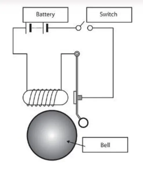
A solenoid is a device comprised of a coil of wire, housing, and a moveable plunger (armature). When an electrical current is introduced, a magnetic field forms around the coil which draws the plunger in. More simply, a solenoid converts electrical energy into mechanical work.
- The coil is made of many turns of tightly wound copper wire. When an electrical current flows through this wire, a strong magnetic field/flux is created.
- The housing, usually made of iron or steel, surrounds the coil concentrating the magnetic field generated by the coil.
- The plunger is attracted to the stop through the concentration of the magnetic field providing the mechanical force to do work.
Components used in the circuit :
- Solenoid
- Switches
- Electrical power supply (DC)
- A bell with pivoted lever
- Some motion sensor for solenoid
Circuit 2: Thermistor
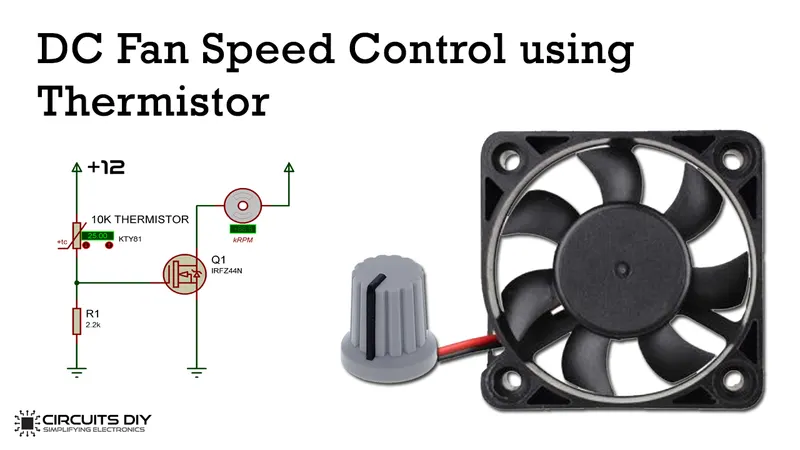
The term thermistor comes from “thermal” and “resistor”. A thermistor is a type of resistor whose resistance is reliant on temperature; it’s a resistance thermometer. They’re made from metallic oxide which is molded into a bead, disk, or cylindrical shape and then enclosed with epoxy or glass.
Thermistors don’t work well with extreme temperatures, but they are perfectly suited for measuring the temperature at a certain point; they’re precise when they’re used within a limited temperature range i.e. within 50 °C of the target temperature; this range is dependent on the base resistance.
How does a thermistor work?
There are two types of thermistors – the most commonly used is the Negative Temperature Coefficient (NTC) thermistor. The NTC’s resistance decreases as the temperature increases, and vice versa. With the Positive Temperature Coefficient (PTC) thermistor, the resistance increases as the temperature increases, and vice versa; it’s normally used as a fuse.
The type of material used in the thermistor will dictate how much the resistance changes, which is changed with temperature. Thermistors are nonlinear i.e. the connection between resistance and temperature won’t form a straight line, it will form a curve on a graph; where the line sits and how much it changes depends on how the thermistor is made. The change in resistance needs to be converted to temperature, which then produces measurable data.
How does a thermistor operate in a controlled system?
A temperature controller monitors the temperature of the thermistor which then instructs a heater or cooler when to turn on or off, in order to maintain the temperature of the sensor (thermistor), as well as the target device. They are used widely in applications such as air conditioning and display fridges/freezers – upon many more.
Component for the circuit :
- Power source
- Thermistor
- Resistance
- Voltage controller
- Switches
- A controlled temperature source
`Simulink model :
Explanation :
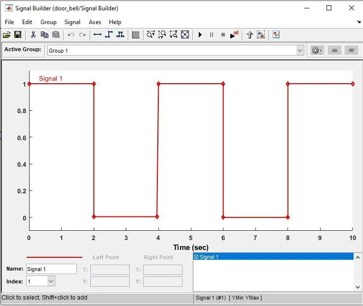
- The doorbell needs to be provided a signal in a way that it should ring for 2 sec and then again stopped. So for this, we need to build a signal in a way that it opens for 2 sec.
- For this, a signal builder is used for the library of electricals in which a graph is created for the 2sec step.
- Then we need to have a power source for the circuit, here a battery is used having an electrical reference ( Simscape circuit needs to have a reference which can be sometimes called as earthing or ground connection).
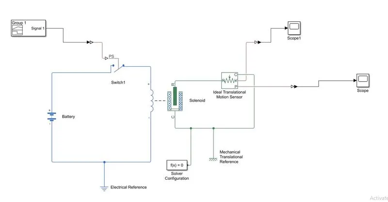
- The battery needs to be connected to a switch which is also a simscape model. This circuit is responsible for controlling the input for the solenoid according to the signal builder function.
- Again the signal builder output needs to be connected to the one port of the switch. But the signal builder is a Simulink component and the switch is a simscape component. Simulink components have output in signal form while the simscape component has an output in the energies form.
- In order to connect the Simulink to simscape, a Simulink-PS converter is used to connect the output signal from the builder to the controlling port of the switch.
- Now, the output of the switch is connected to the solenoid and the other end of the solenoid is connected to the battery to have a proper input electrical circuit.
- The solenoid has a coil and a rod and that rod is displaced by responding to change current to the coil. Here R and C represent the variables for the solenoid.
- R is the plunger and C is the coil or reference or fixed point in the solenoid. To measure the displacement for the solenoid plunger, an ideal translational motion sensor is connected to the solenoid. (R port to R port and C to C port of the sensor). This sensor measures the translational or linear movement of the plunger with respect to the C.
- The motion sensor has two output ports as V and C that are used for displaying the values or for connecting the scope.
- Connections R and C are mechanical translational conserving ports that connect the block to the nodes whose motion is being monitored. Connections V and P are physical signal output ports for velocity and position, respectively.
- The block positive direction is from port R to port C. This means that the velocity is measured as v = VR – VC, where VR, VC are the absolute velocities at ports R and C, respectively.
- Now the solenoid part of the circuit is attached with the mechanical Translational reference to keep a datum or reference point for the movement of the plunger with which the actual displacement of the plunger can be measured.
- Also, the block f(x) is a solver configuration block that needs to be attached to the simscape circuit. The importance of attaching this block is to tell provide the guide to the backend of the Matlab to use the special or certain ode solver to solve the circuit.
- After running the model the below graph is obtained which shows that every 2 sec the pulse is generated at the output and then again it goes to the initial position due to the soring constant of the solenoid.
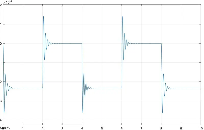
Fig-Position of the plunger plot from P port
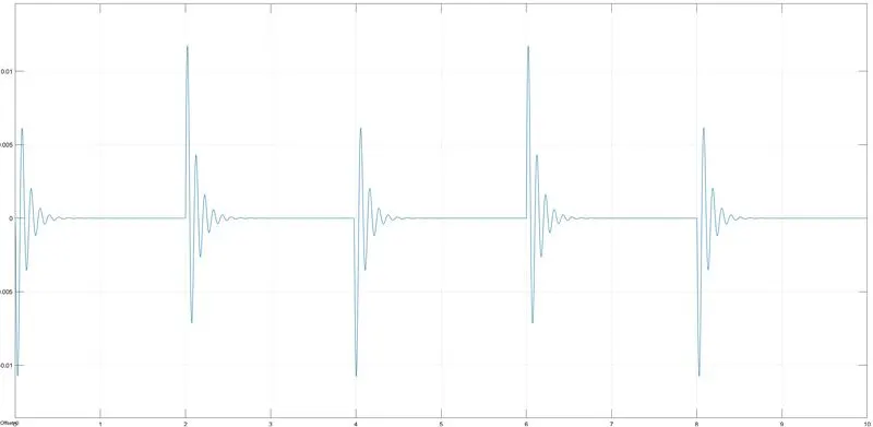
Fig- Velocity plot for the plunger
Circuit 2: Thermistor to sense the temperature of the heater
Simulink model :
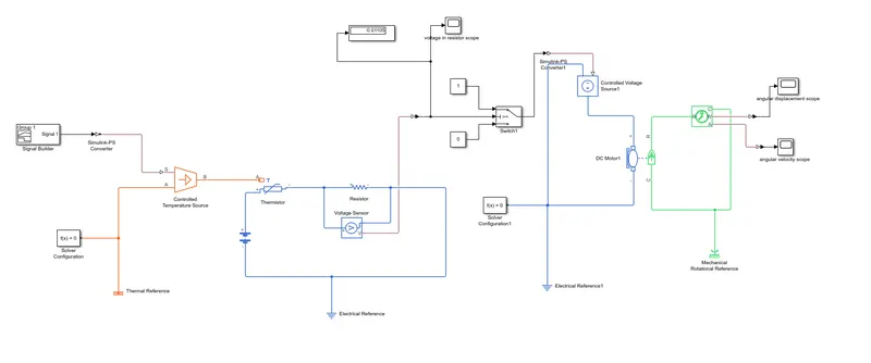
Explanation :
- The circuit for temperature sensing using the thermistor requires a heating source, thermistor, a signal builder, resistor, dc motor, and some switches and voltage regulator.
- The circuit is started with the heater, here this heater is a controlled temperature source that is controlled according to the condition provided by the signal builder.
- So the signal builder will provide the signal in a way that the heater needs to be followed for a certain time period.
- The signal is built inside the signal builder in graph form in which X-axis is the time and the y-axis is the temperature. For the first 10 sec the heater temperature will be 20 degrees celsius and then to 27 for the next 20 sec later which falls to 23-degree celsius for 30-50 sec.(the axes range needs to be changed to 50 sec from menu bar axes>set the time range > 0-50 >set.)
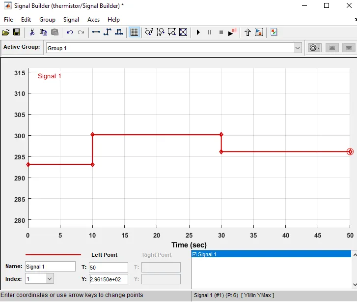
- The one thing to remember here is that the temperature value should be in kelvin as all the parameters for the thermistor is in kelvin only. Also, the signal builder is a Simulink component so the Simulink-PS converter is used to connect the builder to the temperature source.
- Same as in the solenoid circuit a thermal reference ad a solver configuration is attached to the circuit.
- Now the output of the heater is connected to the thermal input port of the thermistor while the rest two ports of the thermistor will be connected with the electrical source.
- Since the Fan needs to be switched on only if a temperature is 25 degrees Celsius and above, a controlling device is necessary here to perform the operation accordingly.
- For that, a resistor along with the voltage regulator or sensor is used in series with the thermistor that will be responsible for the control of the switches.
- A voltage sensor is connected in parallel to the resistor which measures the change in the voltage across the resistor for the time cycle. The output of the voltage sensor is connected to a scope, a display, and a switch block via a PS-Simulink converter.
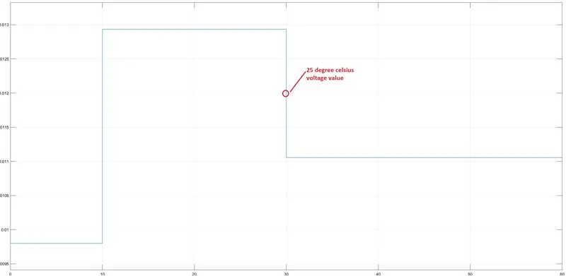
- The switch block routes the signal according to the threshold value condition. The threshold value can be obtained from the scope of the voltage sensor.
- The graph shows the change in voltage with respect to temperature. For the 25 degrees celsius, the value must lie between 23 and 27 which is 0.012 from the voltage graph.
- Now, this value 0.012 needs to be put inside the switch block and the condition is set to u2>threshold which means that switch will be closed when the threshold value is reached. For that two constant blocks is connected to the two ports of the switch with value as 1 and 0 for the close and open condition respectively.
14.The output of the switch is then provided to the dc motor via a controlled voltage source which provides voltage in response to the load.
15.For the motor part, it is again provided with the electrical reference, solver configuration, and an electrical supply.
16.The motor casing and rotor ports are connected with the ideal rotational motion sensor along with a mechanical rotational reference. This motion sensor output ports and then connected to the scope for measuring and plotting the angular velocity and displacement for the motor.
17.The simulation is then run for 50 sec and all the scope plots are obtained by double-clicking on it.
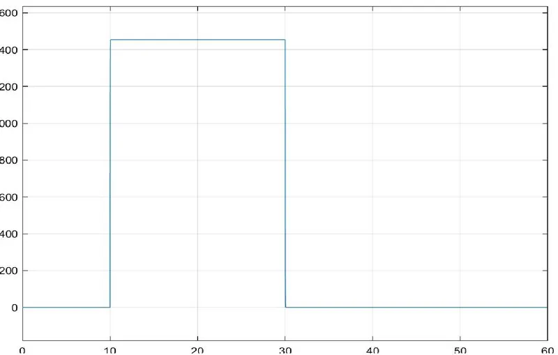
Fig- angular displacement graph for motor
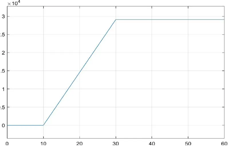
Fig- angular velocity graph for motor
Conclusion :
The Simulink model for the doorbell and thermistor was created successfully.